Page 3260 of 4555
ATC-82
TROUBLE DIAGNOSIS
Blower Motor CircuitEJS004YN
SYMPTOM:
�Blower motor operation is malfunctioning.
�Blower motor operation is malfunctioning under out of starting fan speed control.
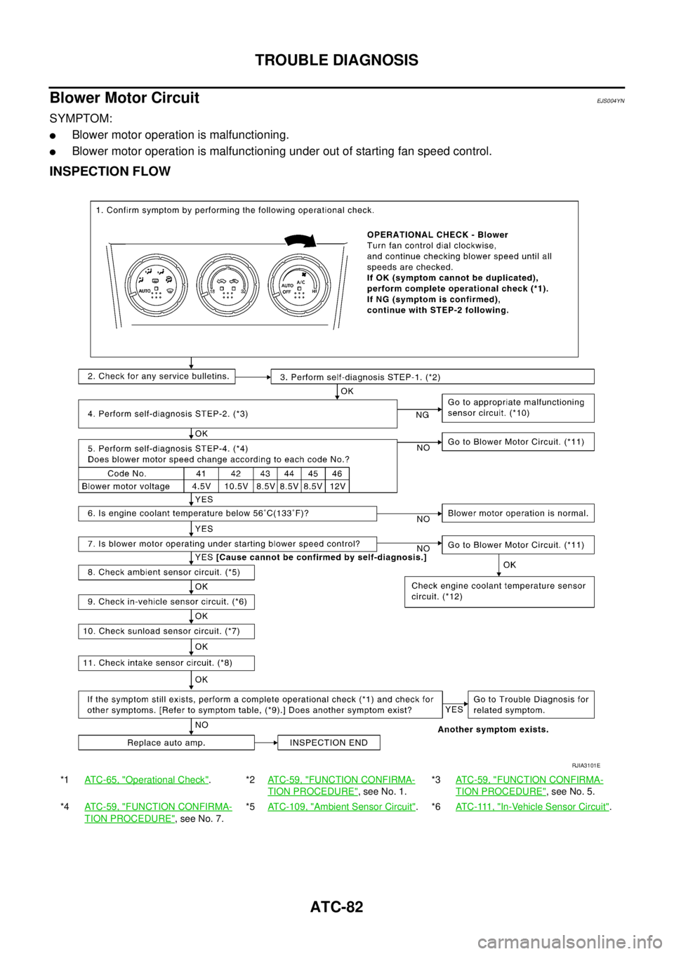
INSPECTION FLOW
*1ATC-65, "Operational Check".*2ATC-59, "FUNCTION CONFIRMA-
TION PROCEDURE", see No. 1.*3ATC-59, "
FUNCTION CONFIRMA-
TION PROCEDURE", see No. 5.
*4ATC-59, "
FUNCTION CONFIRMA-
TION PROCEDURE", see No. 7.*5ATC-109, "
Ambient Sensor Circuit".*6AT C - 111 , "In-Vehicle Sensor Circuit".
RJIA3101E
Page 3261 of 4555

TROUBLE DIAGNOSIS
ATC-83
C
D
E
F
G
H
I
K
L
MA
B
AT C
SYSTEM DESCRIPTION
Component Parts
Fan speed control system components are:
�Auto amp.
�A/C LAN system (PBR built-in air mix door motor, mode door motor and intake door motor)
�Fan control amp.
�In-vehicle sensor
�Ambient sensor
�Sunload sensor
�Intake sensor
System Operation
Automatic Mode
In the automatic mode, the blower motor speed is calculated by the auto amp. based on input from the PBR,
in-vehicle sensor, sunload sensor, intake sensor and ambient sensor.
The blower motor applied voltage ranges from approximately 4 volts (lowest speed) to 12 volts (highest
speed).
The control blower speed (in the range of 4 to 12V), the auto amp. supplies a gate voltage to the fan control
amp. Based on this voltage, the fan control amp. controls the voltage supplied to the blower motor.
*7AT C - 11 4 , "Sunload Sensor Circuit".*8ATC-117, "Intake Sensor Circuit".*9AT C - 3 4 , "SYMPTOM TABLE".
*10AT C - 5 9 , "
FUNCTION CONFIRMA-
TION PROCEDURE", see No. 9.*11ATC-84, "
DIAGNOSTIC PROCE-
DURE FOR BLOWER MOTOR".*12 QR engine; (WITH EURO-OBD) EC-165, "DTC P0117, P0118 ECT SEN-
SOR" .
QR engine; (WITHOUT EURO-OBD)
EC-652, "
DTC P0117, P0118 ECT
SENSOR" .
YD engine; (WITH EURO-OBD) EC-
1093, "DTC P0117, P0118 ECT
SENSOR" .
YD engine; (WITHOUT EURO-OBD)
EC-1449, "
DTC P0117, P0118 ECT
SENSOR" .
RJIA2833E
Page 3262 of 4555

In a cold start up condition where the engine coolant temperature is below 56°C (133°F), the")
ATC-84
TROUBLE DIAGNOSIS
Starting Fan Speed Control
Start Up from COLD SOAK Condition (Automatic mode)
In a cold start up condition where the engine coolant temperature is below 56°C (133°F), the blower will not
operate for a short period of time (up to 150 seconds). The exact start delay time varies depending on the
ambient and engine coolant temperature.
In the most extreme case (very low ambient) the blower starting delay will be 150 seconds as described
above. After this delay, the blower will operate at low speed until the engine coolant temperature rises above
56°C (133°F), and then the blower speed will increase to the objective speed.
Start Up from Usual or HOT SOAK Condition (Automatic mode)
The blower will begin operation momentarily after the A/C switch is pushed. The blower speed will gradually
rise to the objective speed over a time period of 3 seconds or less (actual time depends on the objective
blower speed).
Blower Speed Compensation
Sunload
When the in-vehicle temperature and the set temperature are very close, the blower will be operating at low
speed. The low speed will vary depending on the sunload. During conditions of low or no sunload, the blower
low speed is usual low speed (approx. 4V). During high sunload conditions, the auto amp. causes the blower
fan speed to increase.(Approx. 7V)
Fan Speed Control Specification
COMPONENT DESCRIPTION
Fan Control Amp.
The fan control amp. is located on the intake unit. The fan control
amp. receives a gate voltage from the auto amp. to steplessly main-
tain the blower fan motor voltage in the 4 to 12 volt range.
DIAGNOSTIC PROCEDURE FOR BLOWER MOTOR
SYMPTOM: Blower motor operation is malfunctioning.
RJIA0522E
RJIA0523E
RHA467GA
Page 3263 of 4555

TROUBLE DIAGNOSIS
ATC-85
C
D
E
F
G
H
I
K
L
MA
B
AT C
1. CHECK POWER SUPPLY FOR BLOWER MOTOR
1. Disconnect blower motor connector.
2. Turn ignition switch ON.
3. Check voltage between blower motor harness connector M65
terminal 1 (L/W) and ground.
OK or NG
OK >> GO TO 2.
NG >> Check power supply circuit and 15A fuses [Nos. 19 and
24, located in the fuse block (J/B)]. Refer to PG-79,
"FUSE BLOCK - JUNCTION BOX (J/B)" .
�If OK, check harness for open circuit. Repair or replace if necessary.
�If NG, replace fuse and check harness for short circuit. Repair or replace if necessary.
2. CHECK FAN FEED BACK CIRCUIT
1. Reconnect blower motor connector.
2. Check voltage between auto amp. harness connector M52 ter-
minal 18 (R) and ground.
OK or NG
OK >> GO TO 3.
NG >> GO TO 9.
3. CHECK BLOWER MOTOR
Refer to AT C - 8 7 , "
Blower Motor" .
OK or NG
OK >> GO TO 4.
NG >> Replace blower motor.
4. CHECK POWER SUPPLY FOR FAN CONTROL AMP.
1. Turn ignition switch ON.
2. Check voltage between fan control amp. harness connector
M67 terminal 3 (R) and ground.
OK or NG
OK >> GO TO 5.
NG >> Repair harness or connector.1 – Ground : Battery voltage
RJIA2860E
18 – Ground : Battery voltage
RJIA2861E
Terminals
Condition Voltage (+)
(-)
Fan control
amp. connectorTerminal No.
(wire color)
M67 3 (R) Ground Fan speed: 1st Approx. 8V
RJIA2862E
Page 3265 of 4555
TROUBLE DIAGNOSIS
ATC-87
C
D
E
F
G
H
I
K
L
MA
B
AT C
8. CHECK FAN CONTROL AMP.
1. Turn ignition switch OFF.
2. Disconnect fan control amp. connector.
3. Check continuity between fan control amp. connector M67 ter-
minal 2 and 1.
OK or NG
OK >> GO TO 9.
NG >> Replace fan control amp.
9. CHECK CIRCUIT CONTINUITY BETWEEN AUTO AMP. AND FAN CONTROL AMP.
1. Disconnect auto amp. connector.
2. Check continuity between auto amp. harness connector M52
terminal 18 (R) and fan control amp. harness connector M67 ter-
minal 3 (R).
OK or NG
OK >> Replace auto amp.
NG >> Repair harness or connector.
COMPONENT INSPECTION
Blower Motor
Confirm smooth rotation of blower motor.
�Ensure that there are no foreign particles inside intake unit.2 – 1 : Continuity should exist.
SJIA0476E
18 – 3 : Continuity should exist.
RJIA2867E
RJIA0532E
Page 3270 of 4555

1. Turn ignition switch ON.
2. Check voltage between auto amp. harness connector M52 ter-
minal 4 (L/R) and ground.
OK")
ATC-92
TROUBLE DIAGNOSIS
9. CHECK VOLTAGE FOR AUTO AMP. (COMPRESSOR ON SIGNAL)
1. Turn ignition switch ON.
2. Check voltage between auto amp. harness connector M52 ter-
minal 4 (L/R) and ground.
OK or NG
OK >> GO TO 10.
NG >>
�If the voltage is approx. 5V when the A/C switch is ON: Replace the auto amp.
�If the voltage is approx. 0V when the A/C switch is OFF: GO TO 12.
10. CHECK VOLTAGE FOR AUTO AMP. (FAN ON SIGNAL)
Check voltage between auto amp. harness connector M52 terminal
19 (LG/B) and ground.
OK or NG
OK >> Replace auto amp.
NG >>
�If the voltage is approx. 5V when the blower motor is ON: Replace the auto amp.
�If the voltage is approx. 0V when the blower motor is OFF: GO TO 11.
11 . CHECK CIRCUIT CONTINUITY BETWEEN ECM AND AUTO AMP.
1. Turn ignition switch OFF.
2. Disconnect ECM connector and auto amp. connector.
3. Check continuity between ECM harness connector F43 terminal
96 (LG/B) and auto amp. harness connector M52 terminal 19
(LG/B).
OK or NG
OK >> INSPECTION END
NG >> Repair harness or connector.
Te r m i n a l s
Condition Voltage (+)
(-)
Auto amp.
connectorTerminal No.
(wire color)
M52 4 (L/R) GroundA/C SW: ON
(Blower motor
operates.)Approx. 0V
A/C SW: OFF Approx. 5V
RJIA2873E
Terminals
Condition Voltage (+)
(-)
Auto amp.
connectorTerminal No.
(wire color)
M52 19 (LG/B) GroundBlower fan: ON
(Blower motor
operates.)Approx. 0V
Fan contorol dial:
OFFApprox. 5V
RJIA2874E
96 – 19 : Continuity should exist.
RJIA2837E
Page 3271 of 4555

1. Turn ignition switch OFF.
2. Disconnect ECM connector and auto amp. connect")
TROUBLE DIAGNOSIS
ATC-93
C
D
E
F
G
H
I
K
L
MA
B
AT C
12. CHECK CIRCUIT CONTINUITY BETWEEN ECM AND AUTO AMP. (QR ENGINE)
1. Turn ignition switch OFF.
2. Disconnect ECM connector and auto amp. connector.
3. Check continuity between ECM harness connector F43 terminal
110 (L/R) and auto amp. harness connector M52 terminal 4 (L/
R).
OK or NG
OK >> GO TO 13.
NG >> Repair harness or connector.
13. CHECK VOLTAGE FOR AUTO AMP. (COMPRESSOR ON SIGNAL)
Check voltage between auto amp. harness connector M52 terminal
4 (L/R) and ground.
OK or NG
OK >> Replace auto amp.
NG >> GO TO 17.
14. CHECK DUAL-PRESSURE SWITCH (YD ENGINE)
Refer to AT C - 9 5 , "
Dual-pressure Switch (With Diesel Engine)" .
OK or NG
OK >> GO TO 15.
NG >> Replace the dual-pressure switch.
15. CHECK CIRCUIT CONTINUITY BETWEEN AUTO AMP. AND DUAL-PRESSURE SWITCH
1. Turn ignition switch OFF.
2. Disconnect the auto amp. connector.
3. Check continuity between auto amp. harness connector M52
terminal 4 (L/R) and dual-pressure switch harness connector
E40 terminal 2 (L/R).
OK or NG
OK >> GO TO 16.
NG >> Repair harness or connector.110 – 4 : Continuity should exist.
RJIA2838E
Terminals
Condition Voltage (+)
(-)
Auto amp.
connectorTerminal No.
(wire color)
M52 4 (L/R) GroundA/C SW: ON
(Blower motor
operates.)Approx. 0V
A/C SW: OFF Approx. 5V
RJIA2873E
4 – 2 : Continuity should exist.
RJIA0545E
Page 3275 of 4555
TROUBLE DIAGNOSIS
ATC-97
C
D
E
F
G
H
I
K
L
MA
B
AT C
*10ATC-82, "Blower Motor Circuit".*11AT C - 8 8 , "Magnet Clutch Circuit". *12 QR engine; (WITH EURO-OBD) EC-
352, "System Description" .
QR engine; (WITHOUT EURO-OBD)
EC-755, "
System Description" .
YD engine; (WITH EURO-OBD) EC-
1124, "System Description" .
YD engine; (WITHOUT EURO-OBD)
EC-1480, "
System Description" .
*13ATC-98, "
PERFORMANCE TEST
DIAGNOSIS".

 EC-
352, \"System Description\" .
QR eng")