Page 4019 of 4555
HEADLAMP - XENON TYPE -
LT-23
C
D
E
F
G
H
I
J
L
MA
B
LT
Removal and Installation of Driving LampEKS00N55
REMOVAL
1. Remove cap (front) and cap (rear).
2. Remove driving lamp mounting nut.
3. Pull the front of driving lamp toward upper side so that undo the
pin from roof panel.
4. Remove rear end of driving lamp from roof rail.
5. Pull out driving lamp from vehicle and disconnect connector.
INSTALLATION
Installation is the reverse order of removal.
1. Cap (rear) 2. Driving lamp assembly 3. Nut
4. Cap (front) 5. Driving lamp bracket 6. Grommet
7. Roof rail
PKIC0925E
PKIA3400E
Driving lamp mounting nut
: 5.5 N·m (0.56 kg-m, 49 in-lb)
Page 4035 of 4555
HEADLAMP - CONVENTIONAL TYPE -
LT-39
C
D
E
F
G
H
I
J
L
MA
B
LT
Removal and Installation of Driving LampEKS00N5G
REMOVAL
1. Remove cap (front) and cap (rear).
2. Remove driving lamp mounting nut.
3. Pull the front of driving lamp toward upper side so that undo the
pin from the roof panel.
4. Remove rear end of driving lamp from roof rail.
5. Pull out driving lamp from vehicle and disconnect connector.
INSTALLATION
Installation is the reverse order of removal.
1. Cap (rear) 2. Driving lamp assembly 3. Nut
4. Cap (front) 5. Driving lamp bracket 6. Grommet
7. Roof rail
PKIC0925E
PKIA3400E
Driving lamp mounting nut
: 5.5 N·m (0.56 kg-m, 49 in-lb)
Page 4091 of 4555
TURN SIGNAL AND HAZARD WARNING LAMPS
LT-95
C
D
E
F
G
H
I
J
L
MA
B
LT
Removal and Installation of Side Turn Signal LampEKS003BI
REMOVAL
1. Push the side turn signal lamp toward A direction in the figure,
and pull up B direction in the figure.
2. Disconnect the side turn signal lamp connector.
INSTALLATION
Installation is the reverse order of removal.
Removal and Installation of Rear Turn Signal LampEKS003BJ
Refer to LT- 11 9 , "Removal and Installation" in “REAR COMBINATION LAMP”.
PKIA0469E
Page 4115 of 4555
REAR COMBINATION LAMP
LT-119
C
D
E
F
G
H
I
J
L
MA
B
LT
Bulb ReplacementEKS00164
1. Remove rear combination lamp mounting bolts.
2. Pull rear combination lamp toward rear of vehicle. Disengage
locating pins.
3. Turn bulb socket counterclockwise and unlock it.
4. Remove bulb.
5. Installation is the reverse order of removal.
Removal and InstallationEKS00165
REMOVAL
1. Remove luggage-side lower finisher. Refer to EI-35, "BODY
SIDE TRIM" in “EI EXTERIOR & INTERIOR” section.
2. Disconnect rear combination lamp connector.
3. Remove rear combination lamp mounting bolts.
4. Pull rear combination lamp rearward the vehicle. Disengage
locating pins.
5. Pull harness grommet and remove harness.
INSTALLATION
Installation is the reverse order of removal.Stop/tail lamp : 12V - 21/5W
Rear turn signal lamp : 12V - 21W
Back-up lamp : 12V - 21W
PKIC0923E
PKIA8620E
Rear combination lamp mounting bolts
: 5.4 N·m (0.55 kg-m, 48 in-lb)
Page 4177 of 4555
COMBINATION METERS
DI-29
C
D
E
F
G
H
I
J
L
MA
B
DI
The Fuel Gauge Does Not Move to FULL PositionEKS00EHH
1. QUESTION 1
Does it take a long time for the pointer to move to FULL position?
YES >> GO TO 2.
NO >> GO TO 3.
2. QUESTION 2
Was the vehicle fueled with the ignition switch ON?
YES >> Be sure to fuel the vehicle with the ignition switch OFF. Otherwise, it will take a long time to move
to FULL position because of the characteristic of the fuel gauge.
NO >> GO TO 3.
3. QUESTION 3
Is the vehicle parked on an incline?
YES >> Check the fuel level indication with vehicle on a level surface.
NO >> GO TO 4.
4. QUESTION 4
During driving, does the fuel gauge pointer move gradually toward EMPTY position?
YES >> Check fuel level sensor unit. Refer to DI-25, "Fuel Level Sensor Signal Inspection [Gasoline
Engine Models]" or DI-26, "Fuel Level Sensor Signal Inspection [Diesel Engine Models]" .
NO >> The float arm may interfere or bind with any of the components in the fuel tank.
Page 4224 of 4555
WW-12
FRONT WIPER AND WASHER SYSTEM
Removal and Installation of Front Washer Nozzle EKS0032U
REMOVAL
Push front washer nozzle pawl toward engine hood to pull out.
INSTALLATION
1. After connecting washer hose, press nozzle from cowl top cover surface.
2. Assemble nozzle and socket.
3. Adjust nozzle injection position.
Inspection for Front Washer Nozzle EKS0032V
CHECK VALVE
Blow air in the injection direction, and check that air flows only one
way. Make sure that the reverse direction (inhale) is not possible.
Removal and Installation of Wiper and Washer Switch EKS0032W
REMOVAL
1. Remove steering column cover. Refer to IP-10, "INSTRUMENT
PANEL ASSEMBLY" in “INSTRUMENT PANEL (IP)” section.
2. Remove wiper and washer switch connector.
3. Remove two screws then remove wiper and washer switch from
the spiral cable.
INSTALLATION
Installation is the reverse order of removal.
PKIA9740E
PKIA9741E
SKIA0018E
Page 4500 of 4555

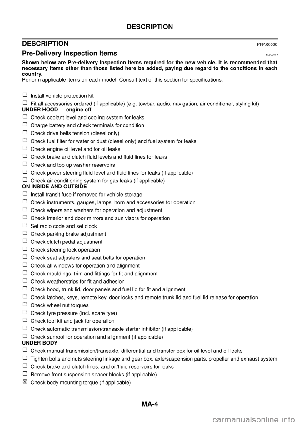
MA-4
DESCRIPTION
DESCRIPTIONPFP:00000
Pre-Delivery Inspection ItemsELS000Y5
Shown below are Pre-delivery Inspection Items required for the new vehicle. It is recommended that
necessary items other than those listed here be added, paying due regard to the conditions in each
country.
Perform applicable items on each model. Consult text of this section for specifications.
Install vehicle protection kit
Fit all accessories ordered (if applicable) (e.g. towbar, audio, navigation, air conditioner, styling kit)
UNDER HOOD — engine off
Check coolant level and cooling system for leaks
Charge battery and check terminals for condition
Check drive belts tension (diesel only)
Check fuel filter for water or dust (diesel only) and fuel system for leaks
Check engine oil level and for oil leaks
Check brake and clutch fluid levels and fluid lines for leaks
Check and top up washer reservoirs
Check power steering fluid level and fluid lines for leaks (if applicable)
Check air conditioning system for gas leaks (if applicable)
ON INSIDE AND OUTSIDE
Install transit fuse if removed for vehicle storage
Check instruments, gauges, lamps, horn and accessories for operation
Check wipers and washers for operation and adjustment
Check interior and door mirrors and sun visors for operation
Set radio code and set clock
Check parking brake adjustment
Check clutch pedal adjustment
Check steering lock operation
Check seat adjusters and seat belts for operation
Check all windows for operation and alignment
Check mouldings, trim and fittings for fit and alignment
Check weatherstrips for fit and adhesion
Check hood, trunk lid, door panels and fuel lid for fit and alignment
Check latches, keys, remote key, door locks and remote trunk lid and fuel lid release for operation
Check wheel nut torques
Check tyre pressure (incl. spare tyre)
Check tool kit and jack for operation
Check automatic transmission/transaxle starter inhibitor (if applicable)
Check sunroof for operation and alignment (if applicable)
UNDER BODY
Check manual transmission/transaxle, differential and transfer box for oil level and oil leaks
Tighten bolts and nuts steering linkage and gear box, axle/suspension parts, propeller and exhaust system
Check brake and clutch lines, and oil/fluid reservoirs for leaks
Remove front suspension spacer blocks (if applicable)
Check body mounting torque (if applicable)
Page 4506 of 4555

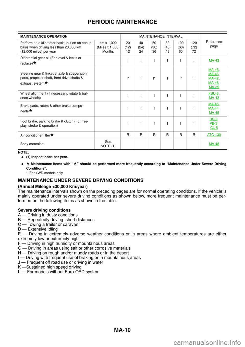
MA-10
PERIODIC MAINTENANCE
NOTE:
�(1) Inspect once per year.
� Maintenance items with “ ” should be performed more frequently according to “Maintenance Under Severe Driving
Conditions”.
*: For 4WD models only.
MAINTENANCE UNDER SEVERE DRIVING CONDITIONS
(Annual Mileage <30,000 Km/year)
The maintenance intervals shown on the preceding pages are for normal operating conditions. If the vehicle is
mainly operated under severe driving conditions as shown below, more frequent maintenance must be per-
formed on the following items as shown in the table.
Severe driving conditions
A — Driving in dusty conditions
B — Repeatedly driving short distances
C — Towing a trailer or caravan
D — Extensive idling
E — Driving in extremely adverse weather conditions or in areas where ambient temperatures are either
extremely low or extremely high
F — Driving in high humidity or mountainous areas
G — Driving in areas using salt or other corrosive materials
H — Driving on rough and/or muddy roads or in the desert
I — Driving with frequent use of braking or in mountainous areas
J — Frequent off road use or driving in water
K —Sustained high speed driving
L — For models without Euro-OBD system
Differential gear oil (For level & leaks or
replace)IIIIIIMA-43
Steering gear & linkage, axle & suspension
parts, propeller shaft, front drive shafts &
exhaust systemI* I I* I I* IMA-45,
MA-46
,
MA-42
,
MA-46
,
MA-39
Wheel alignment (If necessary, rotate & bal-
ance wheels)IIIIIIFSU-6,
MA-43
Brake pads, rotors & other brake compo-
nentsIIIIIIMA-45,
MA-44
,
MA-45
Foot brake, parking brake & clutch (For free
play, stroke & operation)IIIIIIBR-6,
PB-3
,
CL-5
Air conditioner filterRRRRRRATC-130
Body corrosionSee
NOTE (1)MA-48
MAINTENANCE OPERATIONMAINTENANCE INTERVAL
Reference
page Perform on a kilometer basis, but on an annual
basis when driving less than 20,000 km
(12,000 miles) per yearkm x 1,000
(Miles x 1,000)
Months20
(12)
1240
(24)
2460
(36)
3680
(48)
48100
(60)
60120
(72)
72