Page 3488 of 4555
PS-26
POWER STEERING GEAR AND LINKAGE
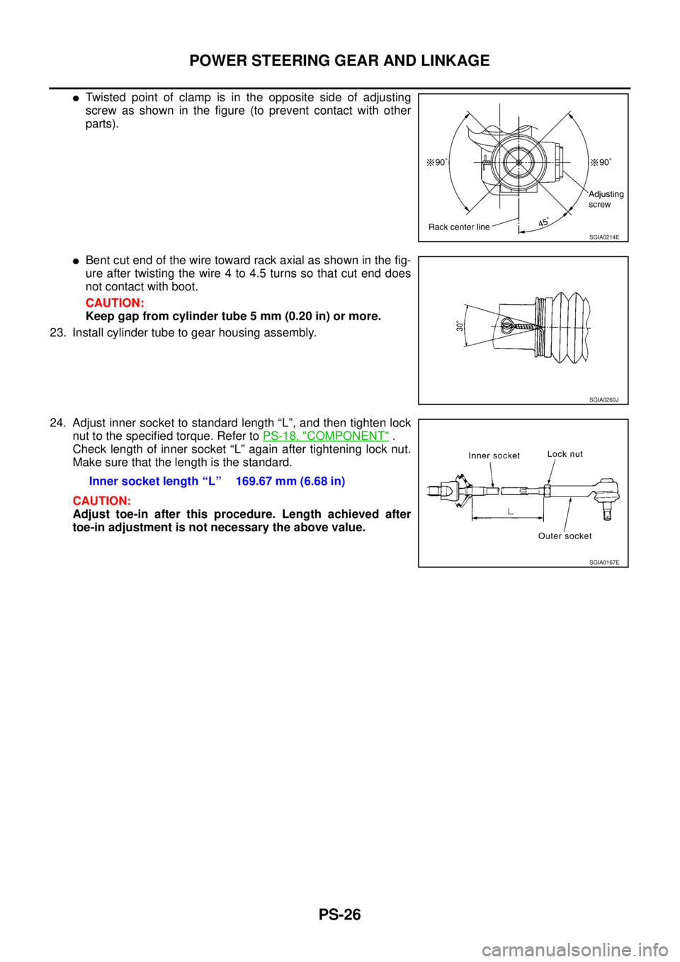
�Twisted point of clamp is in the opposite side of adjusting
screw as shown in the figure (to prevent contact with other
parts).
�Bent cut end of the wire toward rack axial as shown in the fig-
ure after twisting the wire 4 to 4.5 turns so that cut end does
not contact with boot.
CAUTION:
Keep gap from cylinder tube 5 mm (0.20 in) or more.
23. Install cylinder tube to gear housing assembly.
24. Adjust inner socket to standard length “L”, and then tighten lock
nut to the specified torque. Refer to PS-18, "
COMPONENT" .
Check length of inner socket “L” again after tightening lock nut.
Make sure that the length is the standard.
CAUTION:
Adjust toe-in after this procedure. Length achieved after
toe-in adjustment is not necessary the above value.
SGIA0214E
SGIA0260J
Inner socket length “L” 169.67 mm (6.68 in)
SGIA0167E
Page 3496 of 4555
PS-34
POWER STEERING OIL PUMP
DISASSEMBLY
CAUTION:
�Parts which can be disassembled are strictly limited. Never disassemble parts other than those
specified.
�Disassemble in as clean a place as possible.
�Clean your hands before disassembly.
�Do not use rags; use nylon cloths or paper towels.
�Follow the procedure and cautions in the Service Manual.
�When disassembling and reassembling, do not let foreign matter enter or contact the parts.
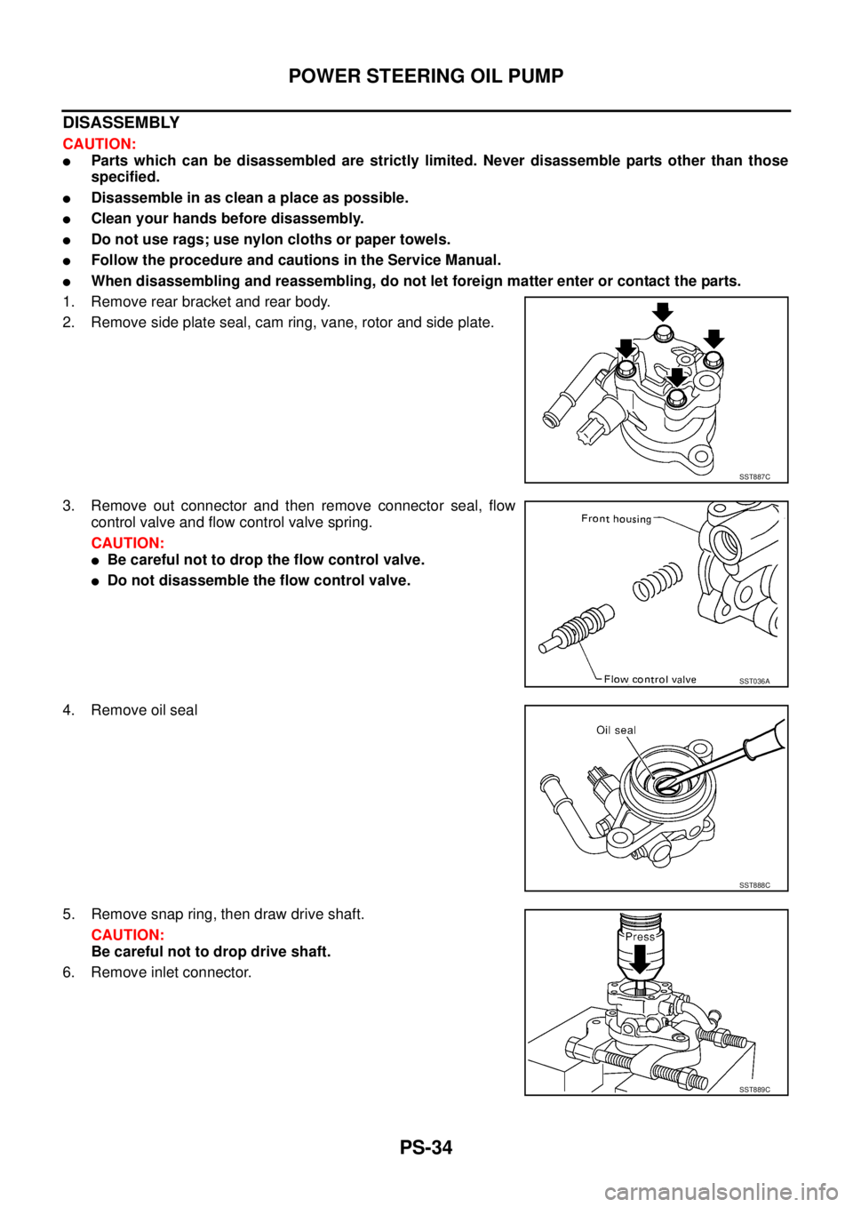
1. Remove rear bracket and rear body.
2. Remove side plate seal, cam ring, vane, rotor and side plate.
3. Remove out connector and then remove connector seal, flow
control valve and flow control valve spring.
CAUTION:
�Be careful not to drop the flow control valve.
�Do not disassemble the flow control valve.
4. Remove oil seal
5. Remove snap ring, then draw drive shaft.
CAUTION:
Be careful not to drop drive shaft.
6. Remove inlet connector.
SST887C
SST036A
SST888C
SST889C
Page 3535 of 4555
 “AIR BAG” and “SEAT
BELT PRE-TENSIONER”
EHS001B0
The Supplemental Restr")
PRECAUTIONS
SRS-3
C
D
E
F
G
I
J
K
L
MA
B
SRS
PRECAUTIONSPFP:00001
Precautions for Supplemental Restraint System (SRS) “AIR BAG” and “SEAT
BELT PRE-TENSIONER”
EHS001B0
The Supplemental Restraint System such as “AIR BAG” and “SEAT BELT PRE-TENSIONER”, used along
with a front seat belt, helps to reduce the risk or severity of injury to the driver and front passenger for certain
types of collision. Information necessary to service the system safely is included in the SRS and SB section of
this Service Manual.
WARNING:
�To avoid rendering the SRS inoperative, which could increase the risk of personal injury or death
in the event of a collision which would result in air bag inflation, all maintenance must be per-
formed by an authorized NISSAN/INFINITI dealer.
�Improper maintenance, including incorrect removal and installation of the SRS, can lead to per-
sonal injury caused by unintentional activation of the system. For removal of Spiral Cable and Air
Bag Module, see the SRS section.
�Do not use electrical test equipment on any circuit related to the SRS unless instructed to in this
Service Manual. SRS wiring harnesses can be identified by yellow and/or orange harnesses or
harness connectors.
Precautions for SRS “AIR BAG” and “SEAT BELT PRE-TENSIONER” ServiceEHS000BH
�Do not use electrical test equipment to check SRS circuits unless instructed to in this Service Manual.
�Before servicing the SRS, turn ignition switch OFF, disconnect both battery cables and wait at least 3 min-
utes.
For approximately 3 minutes after the cables are removed, it is still possible for the air bag and seat belt
pre-tensioner to deploy. Therefore, do not work on any SRS connectors or wires until at least 3 minutes
have passed.
�Diagnosis sensor unit must always be installed with their arrow marks “⇐” pointing towards the front of the
vehicle for proper operation. Also check diagnosis sensor unit for cracks, deformities or rust before instal-
lation and replace as required.
�The spiral cable must be aligned with the neutral position since its rotations are limited. Do not attempt to
turn steering wheel or column after removal of steering gear.
�Handle air bag module carefully. Always place driver and front passenger air bag modules with the pad
side facing upward and place front side air bag module standing with stud bolt side setting bottom.
�Conduct self-diagnosis to check entire SRS for proper function after replacing any components.
�After air bag inflates, the front instrument panel assembly should be replaced if damaged.
Wiring Diagrams and Trouble DiagnosisEHS001NG
When you read wiring diagrams, refer to the following:
�GI-14, "How to Read Wiring Diagrams" in GI section
�PG-2, "POWER SUPPLY ROUTING" in PG section
When you perform trouble diagnosis, refer to the following:
�GI-10, "HOW TO FOLLOW TEST GROUPS IN TROUBLE DIAGNOSES" in GI section
�GI-23, "How to Perform Efficient Diagnosis for an Electrical Incident" in GI section
Check for any service bulletins before servicing the vehicle.
Page 3598 of 4555
BL-16
HOOD
Removal and Installation of Hood Lock ControlEIS009QJ
REMOVAL
1. Remove hood lock cable from hood lock and clip of upper por-
tion of radiator core support and hood ledge.
2. Remove dash side finisher. Refer to EI-35, "
BODY SIDE TRIM" .
3. Remove attaching screw and then the hood opener.
4. Remove dash panel grommet and pull hood lock cable toward
the passenger compartment.
NOTE:
When pulling the cable, be careful not to strip or scratch the
outer surface.
INSTALLATION
1. Pass hood lock cable through the opening while keeping the
winding radius 100 mm (3.94 in) or larger.
2. After confirming that the grommet is properly positioned, push
the grommet securely into the hole.
3. Apply sealant to the area on the grommet indicated with the *
mark.
PIIA3650E
SIIA0156E
PIIA0173E
Page 3675 of 4555

FRONT DOOR LOCK
BL-93
C
D
E
F
G
H
J
K
L
MA
B
BL
14. Remove outside handle mount bolts and slide the outside han-
dle rearward to pull the front end of the outside handle escutch-
eon from the outer panel. Remove outside handle.
INSTALLATION
Install in the reverse order of removal.
NOTE:
�Install the outside handle by pressing it forward and downward while tightening the bolts.
�Install each rod by rotating the rod holder until it engages with a tactile feel.
Disassembly and AssemblyEIS009QP
DISASSEMBLY
NOTE:
The door lock actuator must be removed and installed with the door lock assembly off the vehicle.
1. Remove mount screws and door lock actuator from door lock
assembly.
2. Pull the door lock actuator straight down to separate it from door
lock assembly.
ASSEMBLY
1. Align door lock actuator pivot with the door lock assembly knob lever cutout.
2. Move the knob lever and door lock actuator pivot toward the LOCK position to ensure that they are
securely engaged.
Disassembly and AssemblyEIS009QQ
DISASSEMBLY (SUPER LOCK)
NOTE:
The door lock actuator must be removed and installed with the door lock assembly off the vehicle.
1. Disconnect lock knob rod.
2. Remove mount screws and door lock actuator from door lock
assembly.
3. Pull the door lock actuator straight down to separate it from door
lock assembly.
SIIA0161E
PIIA0558E
PIIB1433E
Page 3676 of 4555
BL-94
FRONT DOOR LOCK
ASSEMBLY
1. Align door lock actuator pivot with the door lock assembly knob lever cutout.
2. Move the knob lever and door lock actuator pivot toward the LOCK position to ensure that they are
securely engaged.
Page 3680 of 4555

BL-98
REAR DOOR LOCK
Disassembly and AssemblyEIS009QV
DISASSEMBLY
NOTE:
The door lock actuator must be removed and installed with the door lock assembly off the vehicle.
1. Remove mount screws and door lock actuator from door lock
assembly.
2. Pull the door lock actuator straight down to separate it from door
lock assembly.
ASSEMBLY
1. Align door lock actuator pivot with the door lock assembly knob lever cutout.
2. Move the knob lever and door lock actuator pivot toward the LOCK position to ensure that they are
securely engaged.
Disassembly and AssemblyEIS009QW
DISASSEMBLY (SUPER LOCK)
NOTE:
The door lock actuator must be removed and installed with the door lock assembly off the vehicle.
1. Disconnect lock knob rod.
2. Remove mount screws and door lock actuator from door lock
assembly.
3. Pull the door lock actuator straight down to separate it from door
lock assembly.
ASSEMBLY
1. Align door lock actuator pivot with the door lock assembly knob lever cutout.
2. Move the knob lever and door lock actuator pivot toward the LOCK position to ensure that they are
securely engaged.
PIIA0560E
PIIB1469E
Page 3795 of 4555

FRONT DOOR GLASS AND REGULATOR
GW-81
C
D
E
F
G
H
J
K
L
MA
B
GW
5. While holding door window, raise it at the rear end to pull glass
out of the sash toward the outside of door.
6. Disconnect power window motor connector.
7. Remove regulator assembly and guide rail mounting bolts
through the access hole.
INSTALLATION
Install in the reverse order of removal.
INSPECTION AFTER REMOVAL
Check regulator assembly for the following items. If a malfunction is
detected, replace or grease it.
�Wire wear
�Regulator deformation
�Grease condition for each sliding part
The arrows in the figure show body grease application points of the
body grease.
INSPECTION AFTER INSTALLATION
Setting of Limit Switch (Driver side)
If any of the following work has been done, set the limit switch (integrated in the motor).
�Removal and installation of regulator
�Removal and installation of motor from the regulator
�Operate regulators as a unit
�Removal and installation of glass
�Removal and installation of glass run
OCC3422D
PIIA0552E
OCC3424D