Page 3798 of 4555
GW-84
REAR DOOR GLASS AND REGULATOR
6. Using a slotted screwdriver or similar tool, remove clip on the
corner inner cover. Slide upper hook to remove, and remove the
cover.
7. Slide the corner inner cover sash cover forward to remove.
8. Remove corner outer cover mounting bolts. Disconnect upper
hook, and remove the cover.
9. Remove mounting nuts on upper portion of rear lower sash.
10. Remove mounting bolts from lower portion of rear lower sash.
11. Rotate rear lower sash, and remove door window from glass
run.
12. Pull out the door window toward the outside of the door to
remove.
13. Remove glass run from rear lower sash.
14. Remove rear lower sash.
15. Disconnect power window motor connector.
SIIA0132E
SIIA0140E
SIIA0133E
SIIA0134E
Page 3818 of 4555

RF-10
SUNROOF
SUNROOFPFP:91210
System DescriptionEIS000MK
�Operating sunroof switch allows glass lid slide OPEN/CLOSE, and tilt UP/DOWN.
�When sunroof slide switch is pressed firmly toward the OPEN side, glass lid automatically opens and
automatic operation is stopped at a point 180 mm (7.09 in)to the fully open position.
NOTE:
After the emergency handle is used to rotate the motor drive shaft, sunroof switch operation may not cor-
respond to actual glass lid movement. When this happens, conduct resuming operation to restore normal
operation.
RESUMING OPERATION
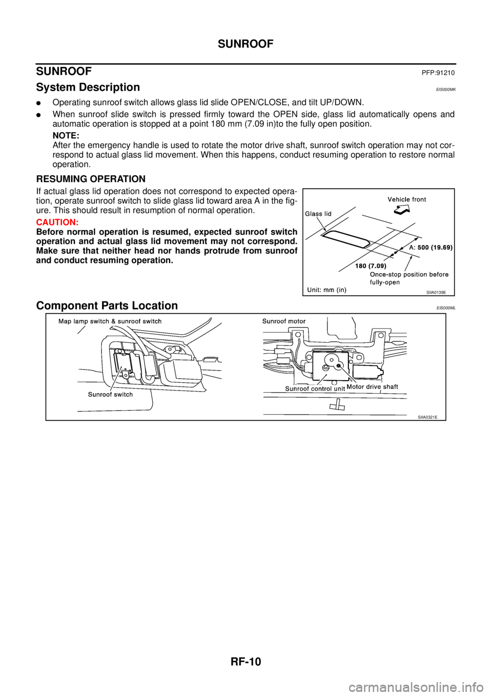
If actual glass lid operation does not correspond to expected opera-
tion, operate sunroof switch to slide glass lid toward area A in the fig-
ure. This should result in resumption of normal operation.
CAUTION:
Before normal operation is resumed, expected sunroof switch
operation and actual glass lid movement may not correspond.
Make sure that neither head nor hands protrude from sunroof
and conduct resuming operation.
Component Parts LocationEIS000ML
SIIA0139E
SIIA0321E
Page 3826 of 4555

RF-18
SUNROOF
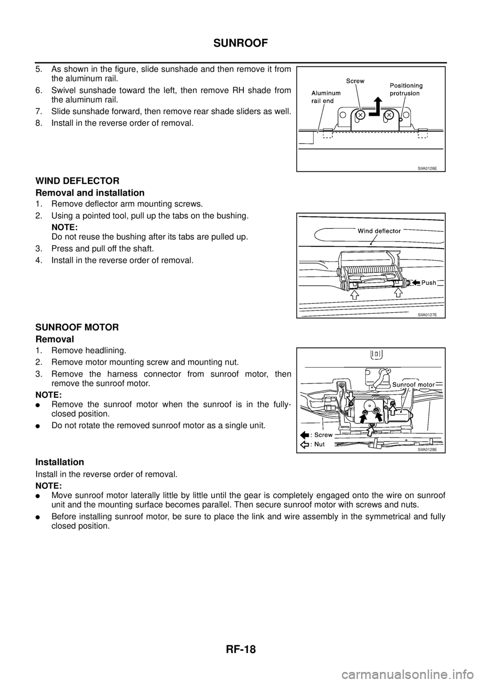
5. As shown in the figure, slide sunshade and then remove it from
the aluminum rail.
6. Swivel sunshade toward the left, then remove RH shade from
the aluminum rail.
7. Slide sunshade forward, then remove rear shade sliders as well.
8. Install in the reverse order of removal.
WIND DEFLECTOR
Removal and installation
1. Remove deflector arm mounting screws.
2. Using a pointed tool, pull up the tabs on the bushing.
NOTE:
Do not reuse the bushing after its tabs are pulled up.
3. Press and pull off the shaft.
4. Install in the reverse order of removal.
SUNROOF MOTOR
Removal
1. Remove headlining.
2. Remove motor mounting screw and mounting nut.
3. Remove the harness connector from sunroof motor, then
remove the sunroof motor.
NOTE:
�Remove the sunroof motor when the sunroof is in the fully-
closed position.
�Do not rotate the removed sunroof motor as a single unit.
Installation
Install in the reverse order of removal.
NOTE:
�Move sunroof motor laterally little by little until the gear is completely engaged onto the wire on sunroof
unit and the mounting surface becomes parallel. Then secure sunroof motor with screws and nuts.
�Before installing sunroof motor, be sure to place the link and wire assembly in the symmetrical and fully
closed position.
SIIA0126E
SIIA0127E
SIIA0128E
Page 3844 of 4555
EI-18
REAR BUMPER
4. Remove mounting bolts and clips on rear bumper fascia.
5. Spread bumper fascia toward the outside and remove it from the side clips.
6. Remove rear fog lamp connectors. Pull bumper fascia assembly straight rearward to remove.
CAUTION:
When removing bumper fascia, 2 workers are required so as to prevent it from dropping.
7. Remove mounting bolts on bumper stay.
8. Remove rear bumper finisher, or rear fog lamps, and the reflectors from bumper.
INSTALLATION
Installation is in the reverse order of removal.
NOTE:
After installation, adjust the clearance.
Page 3883 of 4555
INSTRUMENT PANEL ASSEMBLY
IP-17
C
D
E
F
G
H
J
K
L
MA
B
IP
Glove Box
Open glove box, and remove glove box pin from inside.
Glove Box Cover
1. Remove screw.
2. Remove relay clamp installed to back of glove box cover.
3. Pull it forward to remove.
Upper Glove Box
Disengage pawls and clips, and then pull it straight forward.
Passenger Air Bag Module
Remove passenger air bag module after removing bolts. Refer to SRS-35, "FRONT PASSENGER AIR BAG
MODULE" in SRS section.
Instrument Mask
Insert a screwdriver wrapped with a shop cloth into cutout on instrument mask. Disengage tab to remove.
Front Pillar Garnish
Pull straight front pillar garnish toward vehicle inside of right and left. Remove metal clip to remove.
Refer to EI-35, "
Removal and Installation" in EI section.
PIIA9919E
PIIA9909E
PIIA9910E
Page 3946 of 4555
MTC-22
BLOWER UNIT
BLOWER UNITPFP:27200
Removal and InstallationEJS004YB
REMOVAL
1. Remove glove box assembly.
2. Remove glove box cover, instrument passenger lower panel and instrument reinforcement. Refer to IP-11,
"Removal and Installation" .
3. Remove ECM with ECM bracket attached.
4. Remove instrument panel mounting screw.
5. Remove blower unit mounting bolt and screw.
6. Disconnect blower motor connector and fan resistor connector.
7. Disconnect intake door motor connector and harness clips.
8. Remove blower unit.
CAUTION:
Slide the blower unit toward the right, remove location pins
(2 pieces), then move it downward.
INSTALLATION
Installation is basically the reverse order of removal.
CAUTION:
�Make sure location pins (2 pieces) are securely installed.
RJIA3161E
Page 3959 of 4555
DUCTS AND GRILLES
MTC-35
C
D
E
F
G
H
I
K
L
MA
B
MTC
Removal of Adaptor
1. Remove heater (& cooling) unit. Refer to MTC-27, "HEATER UNIT" .
2. Remove mounting screw and clip.
3. Slide adaptor toward vehicle front, and then remove adaptor.
Removal of Multi-box Duct
1. Remove instrument panel. Refer to IP-11, "Removal and Installation" .
2. Remove mounting screws, and then disconnect multi-box duct
from heater (& cooling) unit.
3. Remove mounting bolts, and then remove heater (& cooling)
unit bracket.
4. Remove multi-box duct from left side.
Removal of Foot Duct
1. Remove multi-box duct.
2. Remove mounting screws, and then remove foot duct.
RJIA2411E
RJIA2412E
RJIA0069E
Page 4000 of 4555

LT-4
PRECAUTION
PRECAUTION PFP:00011
Precautions for Supplemental Restraint System (SRS) “AIR BAG” and “SEAT
BELT PRE-TENSIONER”
EKS0079M
The Supplemental Restraint System such as “AIR BAG” and “SEAT BELT PRE-TENSIONER”, used along
with a front seat belt, helps to reduce the risk or severity of injury to the driver and front passenger for certain
types of collision. Information necessary to service the system safely is included in the SRS and SB section of
this Service Manual.
WARNING:
�To avoid rendering the SRS inoperative, which could increase the risk of personal injury or death
in the event of a collision which would result in air bag inflation, all maintenance must be per-
formed by an authorized NISSAN/INFINITI dealer.
�Improper maintenance, including incorrect removal and installation of the SRS, can lead to per-
sonal injury caused by unintentional activation of the system. For removal of Spiral Cable and Air
Bag Module, see the SRS section.
�Do not use electrical test equipment on any circuit related to the SRS unless instructed to in this
Service Manual. SRS wiring harnesses can be identified by yellow and/or orange harnesses or
harness connectors.
Precaution EKS003KS
�Do not touch the glass of bulb directly by hand. Keep grease and other oily matters away from it. Do not
touch bulb by hand while it is lit or right after being turned off. Burning may result.
�Do not leave bulb out of headlamp reflector for a long time because dust, moisture smoke, etc. may affect
the performance of the headlamp. When replacing the bulb, be sure to replace it with a new one.
�Adjust aiming by tightening aiming screw. (To adjust it toward loosening side, first loosen adjusting screw,
and then make adjustment by tightening.)
�To remove soil or sealant of bulbs, do not use organic solvent (thinner, gasoline, etc.)
�When replacing bulb, be sure to hold bulb socket and pull it out straight. If wiring harness of the bulb is
pulled at an angle, the bulb may be caught in the lamp, making it difficult to take out.
Wiring Diagrams and Trouble Diagnosis EKS003KT
When you read wiring diagrams, refer to the following:
�Refer to GI-14, "How to Read Wiring Diagrams" in GI section
�Refer to PG-2, "POWER SUPPLY ROUTING" for power distribution circuit in PG section
When you perform trouble diagnosis, refer to the following:
�Refer to GI-10, "HOW TO FOLLOW TEST GROUPS IN TROUBLE DIAGNOSES" in GI section
�Refer toGI-23, "How to Perform Efficient Diagnosis for an Electrical Incident" in GI section