Page 1375 of 4555
![NISSAN X-TRAIL 2005 Service Repair Manual SERVICE DATA AND SPECIFICATIONS (SDS)
EC-971
[QR (WITHOUT EURO-OBD)]
C
D
E
F
G
H
I
J
K
L
MA
EC
SERVICE DATA AND SPECIFICATIONS (SDS)PFP:00030
Fuel PressureEBS01158
Idle Speed and Ignition TimingEBS0](/manual-img/5/57403/w960_57403-1374.png "NISSAN X-TRAIL 2005 Service Repair Manual SERVICE DATA AND SPECIFICATIONS (SDS)
EC-971
[QR (WITHOUT EURO-OBD)]
C
D
E
F
G
H
I
J
K
L
MA
EC
SERVICE DATA AND SPECIFICATIONS (SDS)PFP:00030
Fuel PressureEBS01158
Idle Speed and Ignition TimingEBS0")
SERVICE DATA AND SPECIFICATIONS (SDS)
EC-971
[QR (WITHOUT EURO-OBD)]
C
D
E
F
G
H
I
J
K
L
MA
EC
SERVICE DATA AND SPECIFICATIONS (SDS)PFP:00030
Fuel PressureEBS01158
Idle Speed and Ignition TimingEBS01159
*: Under the following conditions:
�Air conditioner switch: OFF
�Electric load: OFF (Lights, heater fan & rear window defogger)
�Steering wheel: Kept in straight-ahead position
Mass Air Flow SensorEBS0115B
*: Engine is warmed up to normal operating temperature and running under no-load.
Intake Air Temperature SensorEBS0115C
Engine Coolant Temperature SensorEBS0115D
Heated Oxygen Sensor 1 HeaterEBS0115E
Heated Oxygen sensor 2 HeaterEBS0115F
Crankshaft Position Sensor (POS)EBS0115G
Refer to EC-699, "Component Inspection" .
Fuel pressure at idle
Approximately 350 kPa (3.5bar, 3.57kg/cm2 , 51psi)
Target idle speedQR20DEM/T No load* (in Neutral position) 650±50 rpm
A/T No load* (in P or N position)
700±50 rpm
QR25DEM/T No load* (in Neutral position)
A/T No load* (in P or N position)
Air conditioner: ONQR20DEM/T In Neutral position
725 rpm or more
A/T In P or N position
QR25DEM/T In Neutral position 750 rpm or more
A/T In P or N position 700 rpm or more
Ignition timingQR20DEM/T In Neutral position
15°±5° BTDC A/T In P or N position
QR25DEM/T In Neutral position
A/T In P or N position
Supply voltageBattery voltage (11 - 14V)
Output voltage at idle0.7 - 1.1*V (QR20DE)
0.8 - 1.2*V (QR25DE)
Temperature °C (°F) Resistance kΩ
25 (77)1.800 - 2.200
80 (176)0.283 - 0.359
Temperature °C (°F) Resistance kΩ
20 (68)2.1 - 2.9
50 (122)0.68 - 1.00
90 (194)0.236 - 0.260
Resistance [at 25°C (77°F)] 3.3 - 4.0Ω
Resistance [at 25°C (77°F)] 5.0 - 7.0Ω
Page 2134 of 4555
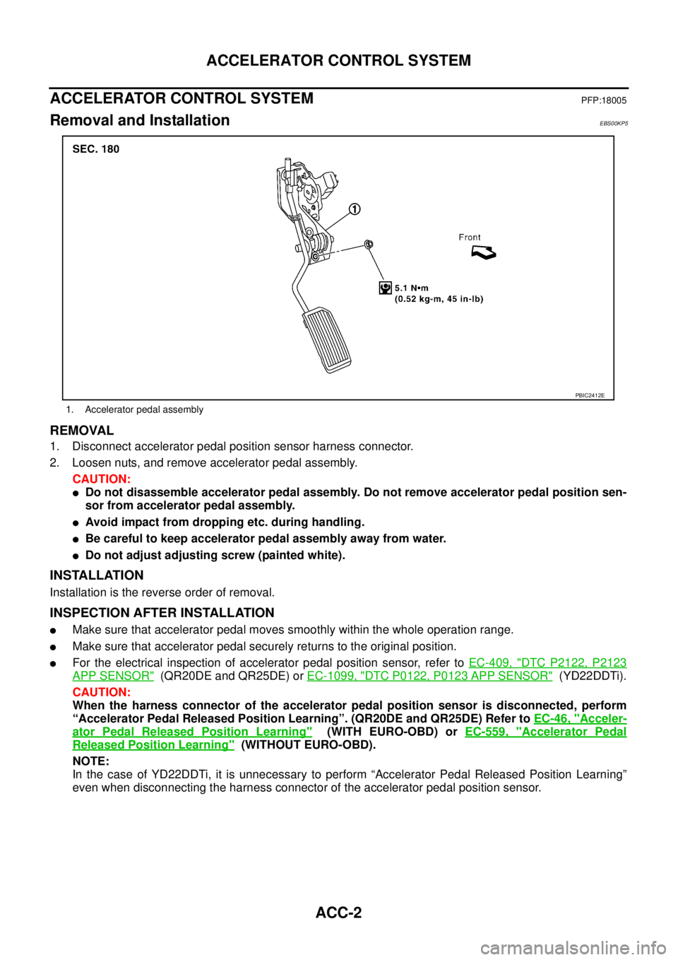
ACC-2
ACCELERATOR CONTROL SYSTEM
ACCELERATOR CONTROL SYSTEMPFP:18005
Removal and InstallationEBS00KP5
REMOVAL
1. Disconnect accelerator pedal position sensor harness connector.
2. Loosen nuts, and remove accelerator pedal assembly.
CAUTION:
�Do not disassemble accelerator pedal assembly. Do not remove accelerator pedal position sen-
sor from accelerator pedal assembly.
�Avoid impact from dropping etc. during handling.
�Be careful to keep accelerator pedal assembly away from water.
�Do not adjust adjusting screw (painted white).
INSTALLATION
Installation is the reverse order of removal.
INSPECTION AFTER INSTALLATION
�Make sure that accelerator pedal moves smoothly within the whole operation range.
�Make sure that accelerator pedal securely returns to the original position.
�For the electrical inspection of accelerator pedal position sensor, refer to EC-409, "DTC P2122, P2123
APP SENSOR" (QR20DE and QR25DE) or EC-1099, "DTC P0122, P0123 APP SENSOR" (YD22DDTi).
CAUTION:
When the harness connector of the accelerator pedal position sensor is disconnected, perform
“Accelerator Pedal Released Position Learning”. (QR20DE and QR25DE) Refer to EC-46, "
Acceler-
ator Pedal Released Position Learning" (WITH EURO-OBD) or EC-559, "Accelerator Pedal
Released Position Learning" (WITHOUT EURO-OBD).
NOTE:
In the case of YD22DDTi, it is unnecessary to perform “Accelerator Pedal Released Position Learning”
even when disconnecting the harness connector of the accelerator pedal position sensor.
1. Accelerator pedal assembly
PBIC2412E
Page 2155 of 4555

SERVICE DATA AND SPECIFICATIONS (SDS)
CL-19
D
E
F
G
H
I
J
K
L
MA
B
CL
SERVICE DATA AND SPECIFICATIONS (SDS)PFP:00030
Clutch Control SystemECS008BH
Clutch Master CylinderECS008BI
Clutch Operating CylinderECS008BJ
Clutch DiscECS008BK
Clutch CoverECS008BL
Type of clutch controlHydraulic
Inner diameter15.87 mm (5/8 in)
Inner diameter19.05 mm (3/4 in)
Engine type QR20DE QR25DE YD22DDTi
Model240
Facing size
(outer dia. x inner dia. x thickness)240 mm x 160 mm x 3.5 mm (9.45 in x 6.30 in x 0.138 in)240 mm x 170 mm x 3.5 mm
(9.45 in x 6.69 in x 0.138 in)
Thickness of disc assembly with load7.90 - 8.30 mm (0.3110 - 0.3268 in) with 5,688 N (580 kg,
1,279 lb)7.70 - 8.10 mm (0.303 -
0.319 in) with 7,845N (800
kg, 1,764 lb)
Wear limit of facing surface to rivet head 0.3 mm (0.012 in)
Runout limit/diameter of the area to be
measured1.0 mm (0.039 in) / 230 mm (9.06 in) dia.
Maximum spline backlash
(at outer edge of disc)1.0 mm (0.039 in)
Engine type QR20DE QR25DE YD22DDTi
Model 240 250
Set-load 4,903 N (500 kg, 1,103 lb) 5,884 N (600 kg, 1,323 lb) 7,600 N (775 kg, 1,708 lb)
Diaphragm spring lever height 37.0 - 39.0 mm (1.457 - 1.535 in)
Uneven limit diaphragm spring toe height 0.7 mm (0.028 in) or less
Page 2259 of 4555
SERVICE DATA AND SPECIFICATIONS (SDS)
MT-103
D
E
F
G
H
I
J
K
L
MA
B
MT
SERVICE DATA AND SPECIFICATIONS (SDS)PFP:00030
General SpecificationsECS008CE
TRANSAXLE
Engine type QR20DE QR25DE YD22DDTi
Transaxle model RS5F51A RS6F51A
Axle type 2WD 4WD 2WD 4WD
Model code number EQ500 EQ000 EQ008 EQ078 EQ068
Number of speed 5 6
Synchromesh type Warner
Shift pattern
5 speed
6 speed
Gear ratio 1st 3.500 3.416 3.500
2nd 1.944
3rd 1.258
4th 0.947
5th 0.772 0.733 0.772
6th — 0.630
Reverse 3.374 3.252 3.374
Final gear 4.750 4.428
Number of
teethInput gear 1st 14 12 14
2nd 18
3rd 31
4th 38
5th 44 45 44
6th — 46
Reverse 14 12 14
Main gear 1st 49 41 49
2nd 35
3rd 39
4th 36
5th 34 33 34
6th — 29
Reverse 38
SCIA0821E
SCIA0955E
Page 2260 of 4555
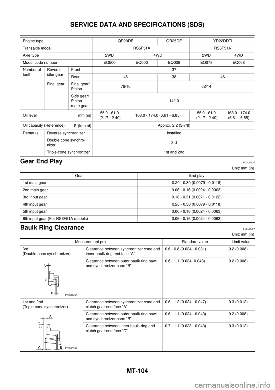
MT-104
SERVICE DATA AND SPECIFICATIONS (SDS)
Gear End PlayECS008CF
Unit: mm (in)
Baulk Ring ClearanceECS00CV4
Unit: mm (in) Number of
teethReverse
idler gearFront 37
Rear 46 38 46
Final gear Final gear/
Pinion76/16 62/14
Side gear/
Pinion
mate gear14/10
Oil level mm (in)55.0 - 61.0
(2.17 - 2.40)168.0 - 174.0 (6.61 - 6.85)55.0 - 61.0
(2.17 - 2.40)168.0 - 174.0
(6.61 - 6.85)
Oil capacity (Reference)
(Imp pt)Approx. 2.2 (3-7/8)
Remarks Reverse synchronizer Installed
Double-cone synchro-
nizer3rd
Triple-cone synchronizer 1st and 2nd Engine type QR20DE QR25DE YD22DDTi
Transaxle model RS5F51A RS6F51A
Axle type 2WD 4WD 2WD 4WD
Model code number EQ500 EQ000 EQ008 EQ078 EQ068
Gear End play
1st main gear0.20 - 0.30 (0.0079 - 0.0118)
2nd main gear 0.06 - 0.16 (0.0024 - 0.0063)
3rd input gear0.18 - 0.31 (0.0071 - 0.0122)
4th input gear0.20 - 0.30 (0.0079 - 0.0118)
5th input gear0.06 - 0.16 (0.0024 - 0.0063)
6th input gear (For RS6F51A models) 0.06 - 0.16 (0.0024 - 0.0063)
Measurement point Standard value Limit value
3rd
(Double-cone synchronizer)Clearance between synchronizer cone and
inner baulk ring end face “A” 0.6 - 0.8 (0.024 - 0.031) 0.2 (0.008)
Clearance between outer baulk ring pawl
and synchronizer cone “B”0.6 - 1.1 (0.024 -0.043) 0.2 (0.008)
1st and 2nd
(Triple-cone synchronizer)Clearance between synchronizer cone and
clutch gear end face “A”0.6 - 1.2 (0.024 - 0.047) 0.3 (0.012)
Clearance between outer baulk ring pawl
and synchronizer cone “B”0.6 - 1.1 (0.024 - 0.043) 0.2 (0.008)
Clearance between inner baulk ring and
clutch gear end face “C”0.7 - 1.1 (0.028 - 0.043) 0.3 (0.012)
PCIB0249E
PCIB0835J
Page 2329 of 4555
TROUBLE DIAGNOSIS — BASIC INSPECTION
AT-65
[EURO-OBD]
D
E
F
G
H
I
J
K
L
MA
B
AT
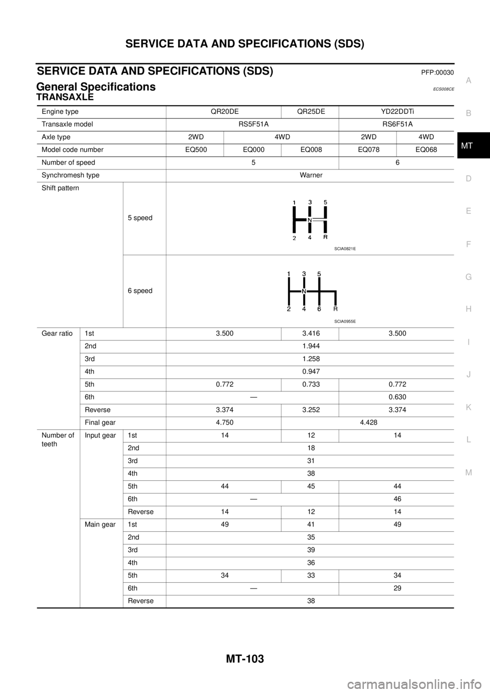
Stall TestECS004QR
STALL TEST PROCEDURE
1. Check A/T fluid and engine oil levels. If necessary, add.
2. Drive vehicle for approx. 10 minutes or until fluid and oil reach
operating temperature. Refer to AT- 1 6 , "
Checking A/T Fluid" .
3. Set parking brake and block wheels.
4. Install a tachometer where it can be seen by driver during test.
�It is good practice to mark the point of specified engine
rpm on indicator.
5. Start engine, apply foot brake, and place selector lever in D
position.
6. Accelerate to wide open throttle gradually while applying foot
brake.
7. Quickly note the engine stall revolution and immediately release
throttle.
�During test, never hold throttle wide open for more than 5
seconds.
SAT647B
SAT513G
SAT775B
Stall revolution:
QR20DE: 2,450 - 2,950 rpm
QR25DE: 2,300 - 2,750 rpm
SAT514G
Page 2521 of 4555
![NISSAN X-TRAIL 2005 Service Repair Manual TROUBLE DIAGNOSIS — BASIC INSPECTION
AT-257
[EXC.F/EURO-OBD]
D
E
F
G
H
I
J
K
L
MA
B
AT
Stall TestECS004VS
STALL TEST PROCEDURE
1. Check A/T fluid and engine oil levels. If necessary, add.
2. Drive](/manual-img/5/57403/w960_57403-2520.png "NISSAN X-TRAIL 2005 Service Repair Manual TROUBLE DIAGNOSIS — BASIC INSPECTION
AT-257
[EXC.F/EURO-OBD]
D
E
F
G
H
I
J
K
L
MA
B
AT
Stall TestECS004VS
STALL TEST PROCEDURE
1. Check A/T fluid and engine oil levels. If necessary, add.
2. Drive")
TROUBLE DIAGNOSIS — BASIC INSPECTION
AT-257
[EXC.F/EURO-OBD]
D
E
F
G
H
I
J
K
L
MA
B
AT
Stall TestECS004VS
STALL TEST PROCEDURE
1. Check A/T fluid and engine oil levels. If necessary, add.
2. Drive vehicle for approx. 10 minutes or until fluid and oil reach
operating temperature. Refer to AT- 1 7 , "
Changing A/T Fluid" .
3. Set parking brake and block wheels.
4. Install a tachometer where it can be seen by driver during test.
�It is good practice to mark the point of specified engine
rpm on indicator.
5. Start engine, apply foot brake, and place selector lever in D
position.
6. Accelerate to wide open throttle gradually while applying foot
brake.
7. Quickly note the engine stall revolution and immediately release
throttle.
�During test, never hold throttle wide open for more than 5
seconds.
8. Move selector lever to N position.
9. Cool off ATF.
�Run engine at idle for at least one minute.
10. Repeat steps 5 through 9 with selector lever in 2, 1 and R posi-
tions.
SAT647B
SAT513G
Stall revolution:
QR20DE: 2,450 - 2,950 rpm
QR25DE: 2,300 - 2,750 rpm
SAT514G
SAT771B
Page 2679 of 4555
![NISSAN X-TRAIL 2005 Service Repair Manual REMOVAL AND INSTALLATION
AT-415
[ALL]
D
E
F
G
H
I
J
K
L
MA
B
AT
21. Remove fluid cooler tube.
INSPECTION
Installation and inspection of torque converter
� After inserting a torque converter to a tra](/manual-img/5/57403/w960_57403-2678.png "NISSAN X-TRAIL 2005 Service Repair Manual REMOVAL AND INSTALLATION
AT-415
[ALL]
D
E
F
G
H
I
J
K
L
MA
B
AT
21. Remove fluid cooler tube.
INSPECTION
Installation and inspection of torque converter
� After inserting a torque converter to a tra")
REMOVAL AND INSTALLATION
AT-415
[ALL]
D
E
F
G
H
I
J
K
L
MA
B
AT
21. Remove fluid cooler tube.
INSPECTION
Installation and inspection of torque converter
� After inserting a torque converter to a transaxle, be sure to
check distance “A” to ensure it is within the reference value limit.
InstallationECS004ND
Install the removed parts in the reverse order of the removal, while paying attention to the following work.
�When installing transaxle to the engine, attach the fixing bolts in
accordance with the following standard.
�Align the positions of tightening bolts for drive plate with those of
the torque converter, and temporarily tighten the bolts. Then,
tighten the bolts to the specified torque. Refer to AT- 4 1 6 , "
Com-
ponents" .
CAUTION:
�When turning crankshaft, turn it clockwise as viewed from
the front of the engine.
�When tightening the tightening bolts for the torque con-
verter after fixing the crankshaft pulley bolts, be sure to
confirm the tightening torque of the crankshaft pulley
mounting bolts.
� After converter is installed to drive plate, rotate crankshaft
several turns and check to be sure that transaxle rotates freely without binding.
�After completing installation, check for fluid leakage, fluid level, and the positions of A/T. Refer to AT- 1 6 ,
"Checking A/T Fluid" , AT- 4 0 9 , "CONTROL CABLE ADJUSTMENT" .
SCIA2596E
Distance “A”
QR20DE models: 19.0 mm (0.75 in) or more
QR25DE models: 14.0 mm (0.55 in) or more
SAT573D
Bolt No.Tightening torque
N·m (kg-m, ft-lb)Bolt length “ L ”
mm (in)
1
75 (7.7, 55)49 (1.93)
2 45 (1.77)
3
43 (4.4, 32)40 (1.57)
4 30 (1.18)
5
36 (3.7, 27)40 (1.57)
6 45 (1.97)
SCIA0795E
SCIA3138E
![NISSAN X-TRAIL 2005 Service Repair Manual TROUBLE DIAGNOSIS — BASIC INSPECTION
AT-65
[EURO-OBD]
D
E
F
G
H
I
J
K
L
MA
B
AT
Stall TestECS004QR
STALL TEST PROCEDURE
1. Check A/T fluid and engine oil levels. If necessary, add.
2. Drive vehicl](/manual-img/5/57403/w960_57403-2328.png "NISSAN X-TRAIL 2005 Service Repair Manual TROUBLE DIAGNOSIS — BASIC INSPECTION
AT-65
[EURO-OBD]
D
E
F
G
H
I
J
K
L
MA
B
AT
Stall TestECS004QR
STALL TEST PROCEDURE
1. Check A/T fluid and engine oil levels. If necessary, add.
2. Drive vehicl")