Page 3877 of 4555

INSTRUMENT PANEL ASSEMBLY
IP-11
C
D
E
F
G
H
J
K
L
MA
B
IP
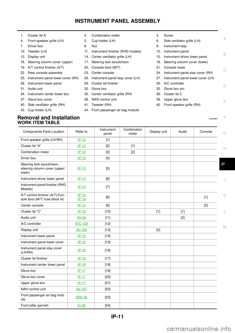
Removal and InstallationEIS008BT
WORK ITEM TABLE
1. Cluster lid A 2. Combination meter 3. Screw
4. Front speaker grille (LH) 5. Cup holder (LH) 6. Side ventilator grille (LH)
7. Driver box 8. Nut 9. Instrument stay
10. Tweeter (LH) 11. Instrument finisher (RHD models) 12. Instrument panel
13. Display unit 14. Center ventilator grille (LH) 15. Instrument driver lower panel
16. Steering column cover (upper) 17. Steering lock escutcheon 18. Steering column cover (lower)
19. A/T control finisher (A/T) 20. Console boot (M/T) 21. Console mask
22. Rear console assembly 23. Center console 24. Instrument panel stay cover (RH)
25. Instrument panel lower cover (RH) 26. Instrument panel stay cover (LH) 27. Instrument panel lower cover (LH)
28. Instrument lower panel 29. Cluster lid finisher 30. A/C controller
31. Audio unit 32. Glove box 33. Glove box pin
34. Instrument center lower box 35. Center ventilator grille (RH) 36. Cluster lid C
37. Glove box cover 38. NAVI control unit 39. Upper glove box
40. Side ventilator grille (RH) 41. Tweeter (RH) 42. Front speaker grille (RH)
43. Cup holder (LH) 44. Front passenger air bag module
Components Parts Location Refer toInstrument
panelCombination
meterDisplay unit Audio Console
Front speaker grille (LH/RH)IP-12
[1]
Cluster lid “A”IP-12
[2] [1]
Combination meterIP-12
[3] [2]
Driver boxIP-13
[4]
Steering lock escutcheon,
steering column cover (upper/
lower)IP-13
[5]
Instrument driver lower panel IP-13
[6]
Instrument panel finisher (RHD
Models)IP-13
[7]
A/T control finisher (A/T)/Con-
sole boot (M/T) fuse block lidIP-14
IP-14[8] [1]
Center consoleIP-14
[9] [2]
Cluster lid “C”IP-15
[10] [1] [1]
Audio unitAV- 3 4
[11] [2]
A/C controllerATC-120
[12]
Display unitAV- 1 0 9
[13] [2]
Instrument lower panelIP-15
[14]
Instrument panel lower cover IP-16
[15]
Instrument panel stay cover
(LH/RH)IP-16
[16]
Cluster lid finisherIP-16
[17]
Instrument center lower panelIP-16
[18]
Glove boxIP-17
[19]
Glove box coverIP-17
[20]
Upper glove boxIP-17
[21]
NAVI control unitAV- 1 0 7
[22]
Front passenger air bag mod-
uleSRS-35
[23]
Front pillar garnishEI-35
[24]
Page 3879 of 4555

INSTRUMENT PANEL ASSEMBLY
IP-13
C
D
E
F
G
H
J
K
L
MA
B
IP
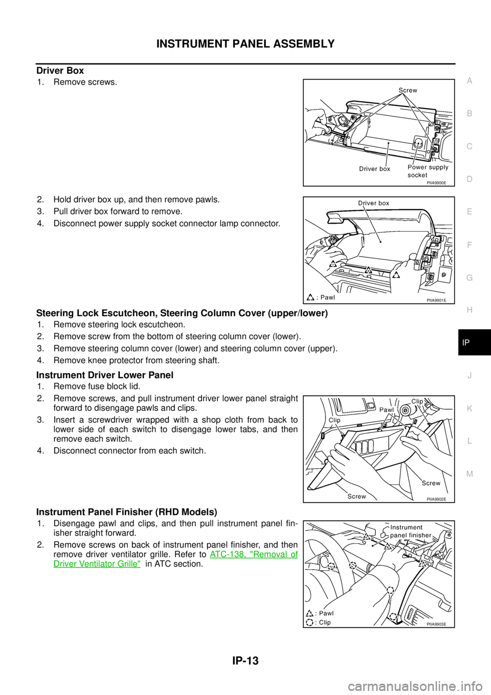
Driver Box
1. Remove screws.
2. Hold driver box up, and then remove pawls.
3. Pull driver box forward to remove.
4. Disconnect power supply socket connector lamp connector.
Steering Lock Escutcheon, Steering Column Cover (upper/lower)
1. Remove steering lock escutcheon.
2. Remove screw from the bottom of steering column cover (lower).
3. Remove steering column cover (lower) and steering column cover (upper).
4. Remove knee protector from steering shaft.
Instrument Driver Lower Panel
1. Remove fuse block lid.
2. Remove screws, and pull instrument driver lower panel straight
forward to disengage pawls and clips.
3. Insert a screwdriver wrapped with a shop cloth from back to
lower side of each switch to disengage lower tabs, and then
remove each switch.
4. Disconnect connector from each switch.
Instrument Panel Finisher (RHD Models)
1. Disengage pawl and clips, and then pull instrument panel fin-
isher straight forward.
2. Remove screws on back of instrument panel finisher, and then
remove driver ventilator grille. Refer to ATC-138, "
Removal of
Driver Ventilator Grille" in ATC section.
PIIA9900E
PIIA9901E
PIIA9902E
PIIA9903E
Page 3884 of 4555
IP-18
INSTRUMENT PANEL ASSEMBLY
Instrument Panel
1. Remove nuts, and lower steering column.
2. Remove instrument panel by removing all harnesses, bolts, nuts, and screw.
Side Ventilator Grille (LH/RH)
1. Remove front driver side ventilator duct and front passenger side ventilator duct. Refer to ATC-138,
"Removal of Defroster Nozzle, Duct and Side Ventilator Duct" in ATC section.
2. Remove front driver side ventilator and front passenger side ventilator. Refer to ATC-138, "
Removal of
Side Ventilator Grille" in ATC section.
Cup Holder (LH/RH)
Remove screws and remove cup holder.
INSTALLATION
Install in the reverse order of removal.
SIIA0040E
PIIA9911E
Page 3951 of 4555
HEATER UNIT
MTC-27
C
D
E
F
G
H
I
K
L
MA
B
MTC
HEATER UNITPFP:27100
Removal and InstallationEJS001F9
REMOVAL
1. Drain coolant from cooling system. Refer to CO-9, "Changing Engine Coolant" for QR engine or CO-32,
"Changing Engine Coolant" for YD engine.
2. Disconnect two heater hoses from heater core pipe.
3. Remove instrument panel. Refer to IP-11, "
Removal and Installation" .
4. Remove blower unit. Refer to MTC-22, "
BLOWER UNIT" .
5. Remove clips of vehicle harness from steering member.
6. Remove mounting nuts, and then remove instrument stay.
7. Remove mounting bolts from heater (& cooling) unit.
RJIA0060E
RJIA0061E
RJIA2444E
Page 3952 of 4555
MTC-28
HEATER UNIT
8. Remove steering member.
NOTE:
This illustration is for RHD models. The layout for LHD models is symmetrically opposite.
9. Remove heater unit.
INSTALLATION
Installation is basically the reverse order of removal.
NOTE:
When filling radiator with coolant, refer to CO-9, "
Changing Engine Coolant" for QR engine or CO-32, "Chang-
ing Engine Coolant" for YD engine.
RJIA2404E
Page 4092 of 4555

LT-96
LIGHTING AND TURN SIGNAL SWITCH
LIGHTING AND TURN SIGNAL SWITCHPFP:25540
Removal and InstallationEKS0034F
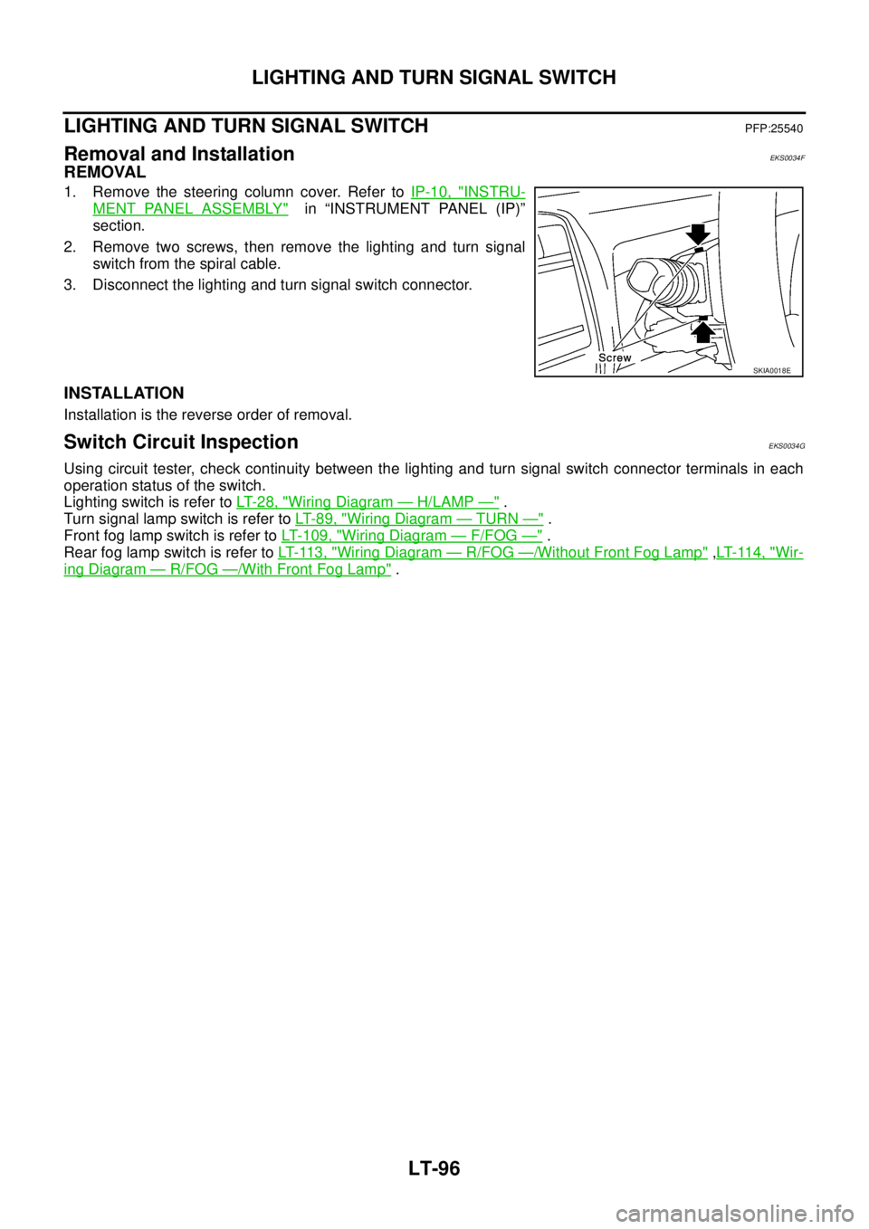
REMOVAL
1. Remove the steering column cover. Refer to IP-10, "INSTRU-
MENT PANEL ASSEMBLY" in “INSTRUMENT PANEL (IP)”
section.
2. Remove two screws, then remove the lighting and turn signal
switch from the spiral cable.
3. Disconnect the lighting and turn signal switch connector.
INSTALLATION
Installation is the reverse order of removal.
Switch Circuit InspectionEKS0034G
Using circuit tester, check continuity between the lighting and turn signal switch connector terminals in each
operation status of the switch.
Lighting switch is refer to LT- 2 8 , "
Wiring Diagram — H/LAMP —" .
Turn signal lamp switch is refer to LT- 8 9 , "
Wiring Diagram — TURN —" .
Front fog lamp switch is refer to LT- 1 0 9 , "
Wiring Diagram — F/FOG —" .
Rear fog lamp switch is refer to LT- 11 3 , "
Wiring Diagram — R/FOG —/Without Front Fog Lamp" ,LT- 11 4 , "Wir-
ing Diagram — R/FOG —/With Front Fog Lamp" .
SKIA0018E
Page 4157 of 4555
COMBINATION METERS
DI-9
C
D
E
F
G
H
I
J
L
MA
B
DI
TYPE 4/TYPE 5
System diagram
Input/output signal chart
T: Transmit R: Receive ASCD SET lamp signal TR
ASCD CRUISE lamp signal TR Signals ECM TCMABS actuator
and electric unit
(control unit)4WD control
unitCombination
meter
PKIA9634E
Signals ECMESP/TCS/ABS
control unitSteering angle
sensor4WD control
unitCombination
meter
4WD mode indicator lamp signalTR
4WD warning lamp signalTR
A/C compressor feedback signal*
2TR
A/C switch signal*
1RT
ABS warning lamp signal T R
Accelerator pedal position signal T R R
Brake warning lamp signal T R
Engine coolant temperature signal TR
Engine speed signal T R R R
ESP OFF indicator lamp signal T R
Glow indicator lamp signal*1 TR
MI signal TR
Stop lamp switch signal T R
Vehicle speed signalTRR
RT
SLIP indicator lamp signal T R
Parking brake switch signalRT
Steering angle sensor signal R T
ASCD SET lamp signal TR
ASCD CRUISE lamp signal TR
Page 4158 of 4555
DI-10
COMBINATION METERS
*1: YD engine models only
*2: QR engine models only
TYPE 6
System diagram
Input/output signal chart
T: Transmit R: Receive
PKIA9635E
Signals ECM TCMESP/TCS/
ABS control
unitSteering
angle sensor4WD control
unitCombination
meter
4WD mode indicator lamp signalTR
4WD warning lamp signalTR
A/C compressor feedback signal TR
A/T position indicator lamp signal T R R
A/T self-diagnosis signal R T
ABS warning lamp signal T R
Accelerator pedal position signal T R R
Brake warning lamp signal T R
Closed throttle position signal T R
Engine and A/T integratedTR
RT
Engine coolant temperature signal TR
Engine speed signal T R R R
ESP OFF indicator lamp signal T R
MI signal TR
O/D OFF indicator signal T R
Output shaft revolution signal R T
Overdrive control switch signal R T
P·N range signal R T
SLIP indicator lamp signal T R
Steering angle sensor signal R T