Page 3497 of 4555
POWER STEERING OIL PUMP
PS-35
C
D
E
F
H
I
J
K
L
MA
B
PS
INSPECTION AFTER DISASSEMBLY
�If pulley is cracked or deformed, replace it.
�If an oil leak is found around pulley shaft oil seal, replace the seal.
�If serration on pulley or pulley shaft is deformed or worn, replace it.
ASSEMBLY
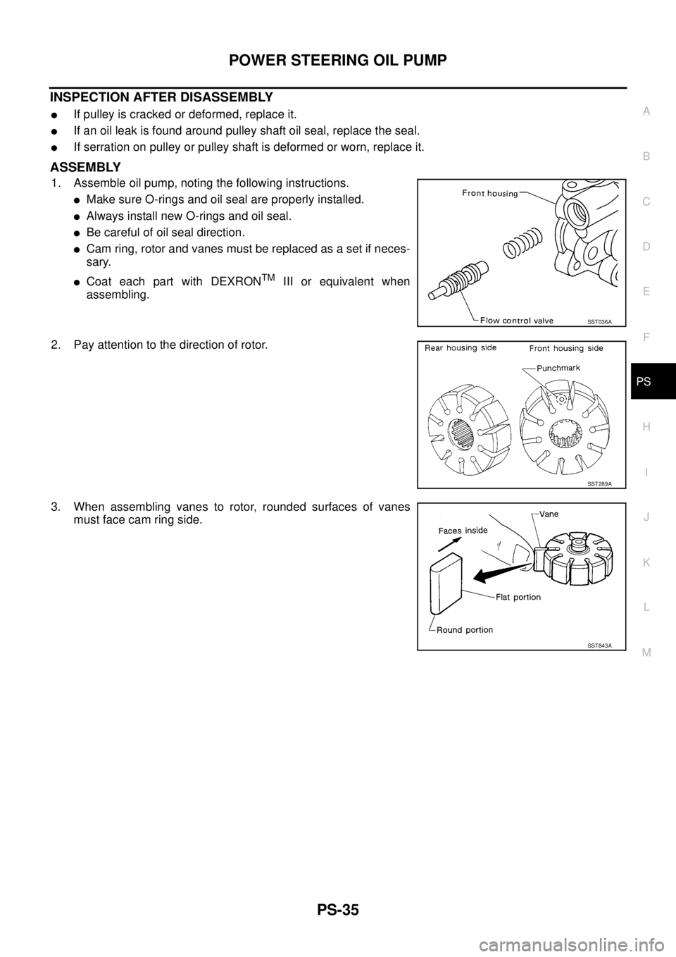
1. Assemble oil pump, noting the following instructions.
�Make sure O-rings and oil seal are properly installed.
�Always install new O-rings and oil seal.
�Be careful of oil seal direction.
�Cam ring, rotor and vanes must be replaced as a set if neces-
sary.
�Coat each part with DEXRONTM III or equivalent when
assembling.
2. Pay attention to the direction of rotor.
3. When assembling vanes to rotor, rounded surfaces of vanes
must face cam ring side.
SST036A
SST289A
SST843A
Page 3498 of 4555
PS-36
POWER STEERING OIL PUMP
4. Insert pin 2 into pin groove 1 of front housing and front side
plate. Then install cam ring 3 as shown at left.
Cam ring : D
1 is less than D2
SST472C
Page 3500 of 4555
PS-38
HYDRAULIC LINE
QR20DE RH MODEL
1. Reservoir tank 2. Suction hose 3. High-pressure hose
4. Oil pump assembly 5. Steering gear assembly 6. Pressure sensor
7. O-ring 8. Copper washer 9. Eye-joint (assembled to high-pres-
sure side hose)
10. Eye-bolt
SGIA0945E
Page 3501 of 4555
HYDRAULIC LINE
PS-39
C
D
E
F
H
I
J
K
L
MA
B
PS
QR25DE LH MODEL
1. Reservoir tank 2. Suction hose 3. High-pressure hose
4. Oil pump assembly 5. Steering gear assembly 6. Pressure sensor
7. O-ring 8. Copper washer 9. Eye-joint (assembled to high-pres-
sure side hose)
10. Eye-bolt
SGIA0946E
Page 3502 of 4555
PS-40
HYDRAULIC LINE
QR25DE RH MODEL
1. Reservoir tank 2. Suction hose 3. High-pressure hose
4. Oil pump assembly 5. Steering gear assembly 6. Pressure sensor
7. O-ring 8. Copper washer 9. Eye-joint (assembled to high-pres-
sure side hose)
10. Eye-bolt
SGIA0947E
Page 3503 of 4555
HYDRAULIC LINE
PS-41
C
D
E
F
H
I
J
K
L
MA
B
PS
YD22DDTi LH MODEL
1. Reservoir tank 2. Suction hose 3. High-pressure hose
4. Oil pump assembly 5. Steering gear assembly 6. Pressure sensor
7. O-ring 8. Copper washer 9. Eye-joint (assembled to high-pres-
sure side hose)
10. Eye-bolt
SGIA0948E
Page 3504 of 4555
PS-42
HYDRAULIC LINE
YD22DDTi RH MODEL
1. Reservoir tank 2. Suction hose 3. High pressure hose
4. Oil pump assembly 5. Steering gear assembly 6. Pressure sensor
7. O-ring 8. Copper washer 9. Eye-joint (assembled to high-pres-
sure side hose
10. Eye-bolt
SGIA0949E
Page 3505 of 4555
HYDRAULIC LINE
PS-43
C
D
E
F
H
I
J
K
L
MA
B
PS
REMOVAL AND INSTALLATION
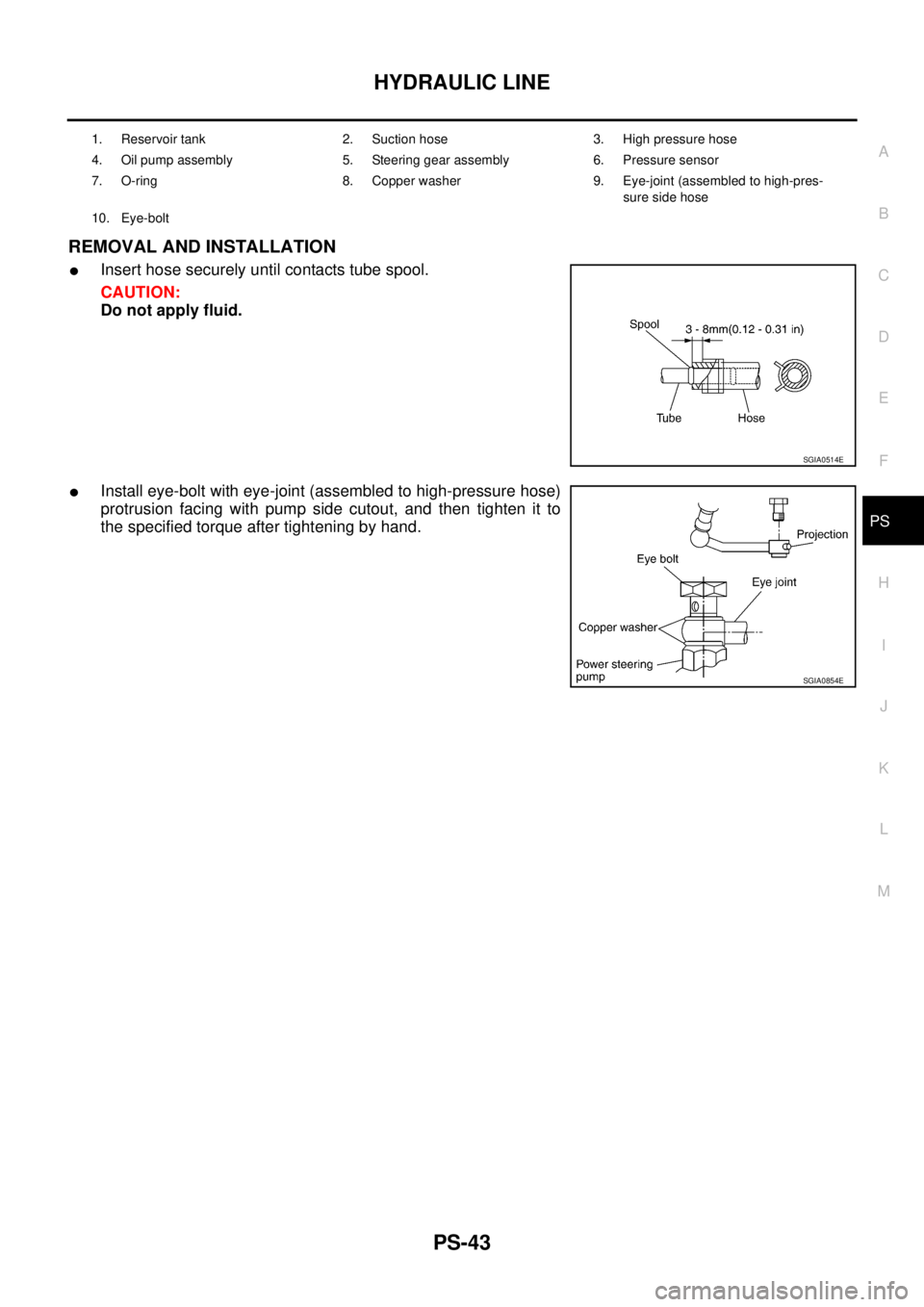
�Insert hose securely until contacts tube spool.
CAUTION:
Do not apply fluid.
�Install eye-bolt with eye-joint (assembled to high-pressure hose)
protrusion facing with pump side cutout, and then tighten it to
the specified torque after tightening by hand.
1. Reservoir tank 2. Suction hose 3. High pressure hose
4. Oil pump assembly 5. Steering gear assembly 6. Pressure sensor
7. O-ring 8. Copper washer 9. Eye-joint (assembled to high-pres-
sure side hose
10. Eye-bolt
SGIA0514E
SGIA0854E