Page 3489 of 4555

POWER STEERING OIL PUMP
PS-27
C
D
E
F
H
I
J
K
L
MA
B
PS
POWER STEERING OIL PUMPPFP:49110
On-Vehicle Inspection and ServiceEGS000AF
OIL PUMP PULLEY HYDRAULIC PRESSURE INSPECTION
Before starting following procedure, check tension of belt.
1. Raise vehicle. Connect oil pressure gauge between oil pump
discharge connector and high pressure hose. Then bleed the
hydraulic circuit.
2. Start engine. Run engine until oil temperature reaches 50°C -
80°C (122 - 176°F).
CAUTION:
�Leave valve of hydraulic pressure gauge fully open while
starting and running engine. If engine is started with
valve closed, hydraulic pressure in oil pump goes up.
This will relief pressure along with abnormal increase of
oil temperature.
�Care must be taken to keep hose clear of belt and other parts when engine is started.
3. Fully close hydraulic pressure gauge valve with engine at idle. Measure relief pressure.
4. After measurement, open valve slowly.
CAUTION:
Never keep valve closed for 10 seconds or longer.
�If relief pressure is outside specification, disassemble and service oil pump. Refer to PS-28, "Disas-
sembly and Assembly(QR20DE and QR25DE Engine Models)" , PS-33, "Disassembly and Assembly
(YD22DDTi Engine Model)" .
5. After inspection, remove oil pressure gauge from hydraulic circuit. Add fluid. Be sure to bleed the system
completely. Refer to PS-6, "
Air Bleeding Hydraulic System" .
Removal and Installation (QR20DE and QR25DE Engine Models)EGS000AG
REMOVAL
1. Loosen adjusting screw and oil pump mounting bolt. Then, remove belt.
2. Remove union bolt and hose for oil pump.
3. Remove oil pump bracket attaching bolt.
4. Remove oil pump from vehicle.
INSTALLATION
Paying attention to following items, install in the reverse order of removal.
�After installation, adjust belt tension. Refer to EM-13, "DRIVE BELTS" .
�After installation, be sure to bleed system. Refer to PS-6, "Air Bleeding Hydraulic System" . Relief oil pressure
Except YD22DDTi models
: 8,000 - 8,800 kPa (81.60 - 89.76 kg/cm
2 , 1,160 - 1,276 psi)
YD22DDTi models
: 8,500 - 9,300 kpa (98 - 104 kg/cm
2 , 1,390 - 1,480 psi)
SST834-H
Page 3490 of 4555
EGS000AH
INSPECTION BEFORE DISASSEMBLY
Disassemble the power steering oil pump only if the following items
are")
PS-28
POWER STEERING OIL PUMP
Disassembly and Assembly(QR20DE and QR25DE Engine Models)EGS000AH
INSPECTION BEFORE DISASSEMBLY
Disassemble the power steering oil pump only if the following items
are found.
�Oil leak from any point shown in the figure
�Deformed or damaged pulley
�Poor performance
DISASSEMBLY
1. Fix power steering pump in a vise.
CAUTION:
When fixing pump in a vise, use aluminum plates to protect steering pump mounting surface.
2. Remove rear bracket mounting bolts. Remove rear bracket from rear body.
3. Remove three front bracket attaching bolts and remove front bracket from casing.
4. Remove four rear body attaching bolts and remove rear body from casing.
5. Remove body seal from casing.
6. Remove side plate (rear) from cartridge. Remove side plate inner and outer seals from side plate (rear).
1. Pulley 2. Front bracket 3. Drive shaft seal
4. Casing 5. Inlet connector seal 6. Inlet connector
7. Flow control valve spring 8. Flow control A valve 9. Dowel pin
10. Flow control B valve assembly 11. Side plate (front) 12. Cartridge
13. Rotor 14. Vane 15. Rotor snap ring
16. Side plate (rear) 17. Side plate inner seal 18. Side plate outer seal
19. Body seal 20. Rear body 21. Rear bracket
SGIA0645E
SST984A
Page 3491 of 4555

POWER STEERING OIL PUMP
PS-29
C
D
E
F
H
I
J
K
L
MA
B
PS
7. Remove rotor snap ring using a snap ring pliers and remove pul-
ley from casing.
CAUTION:
When removing rotor snap ring, be careful not to damage
pulley shaft.
8. Remove following parts from casing: cartridge, rotor, vane, side
plate (front), flow control valve A, flow control valve spring, and
flow control valve B assembly
CAUTION:
Do not drop flow control A valve and flow control B valve
assembly to floor. If dropped, they may be deformed.
9. Remove inlet connector attaching bolt and remove inlet connector from casing.
10. Remove inlet connector seal from inlet connector.
11. Using a screwdriver or equivalent tool, remove drive shaft seal from casing.
CAUTION:
Be careful not to damage casing surface with screwdriver.
INSPECTION AFTER DISASSEMBLY
Inspecting Casing and Rear Body
�Check casing and rear body for internal damage. If rear body is damaged, replace rear body. If casing is
damaged, replace power steering pump assembly.
Cartridge Inspection
�Check cartridge for damage. If damaged, cartridge, rotor, and vane must be replaced as a set.
Inspecting Side Plate
�Check side plates (front and rear) for damage. If damaged, side plates (front and rear) must be replaced
as a set.
ASSEMBLY
1. Apply multi-purpose grease to lip of drive shaft seal. Using a
drift, install drive shaft seal to casing.
CAUTION:
Drive shaft seal is not reusable. Never reuse drive shaft
seal.
2. If removed dowel pin cannot be inserted to casing by hand, tap
it with hammer.
3. Connect flow control valve A, flow control valve spring and flow
control valve B assembly as shown.
SGIA0059E
SST038A
SGIA0061E
Page 3492 of 4555
PS-30
POWER STEERING OIL PUMP
4. Align dowel pin A on flow control valve A with notch B in side
plate (front) as shown. Install side plate (front) to casing.
5. Install cartridge onto front side plate with smaller slit of cartridge
facing casing.
6. Connect pulley to casing.
CAUTION:
Be careful not to damage drive shaft seal when installing
pulley.
7. Connect rotor to pulley shaft with punch mark on rotor facing
casing.
8. Connect vane to rotor with arc of vane in contact with cartridge.
SGIA0062E
SST497A
SST289A
SST843A
Page 3493 of 4555

POWER STEERING OIL PUMP
PS-31
C
D
E
F
H
I
J
K
L
MA
B
PS
9. Connect rotor snap ring to slit of pulley shaft, using a hammer
and a 10-mm socket.
CAUTION:
� Rotor snap ring is not reusable. Never reuse rotor snap
ring.
�Be careful not to damage rotor and pulley shaft.
�If rotor is damaged, power steering pump assembly must
be replaced.
10. Align dowel pin A on flow control valve A with notch B in side
plate (rear) as shown. Install side plate (rear) to cartridge.
11. Apply DEXRON
TM III or equivalent to body seal. Install it to cas-
ing.
CAUTION:
Body seal is not reusable. Never reuse body seal.
12. Apply DEXRON
TM III or equivalent to side plate inner and outer
seals. Install them to side plate (rear).
CAUTION:
Side plate inner and outer seals are not reusable. Never
reuse side plate inner and outer seals.
13. Fix power steering pump in a vise.
CAUTION:
When fixing pump in a vise, use aluminum plates to protect
steering pump mounting surface.
14. Attach rear body to casing and tighten four mounting bolts diag-
onally to specified torque.
15. Install rear bracket to rear body. Tighten mounting bolts to specified torque.
16. Connect front bracket to casing and tighten mounting bolts (3) to specified torque.
17. Connect inlet connector seal to inlet connector slit. Install inlet connector to casing with attaching bolts.
CAUTION:
Inlet connector seal is not reusable. Never reuse inlet connector seal.
SGIA0063E
SGIA0064E
SGIA0065E
Page 3494 of 4555
PS-32
POWER STEERING OIL PUMP
Removal and Installation (YD22DDTi Engine Model)EGS000AI
1. Remove chain case cover.
2. Revolving crank pulley, set sprocket holder [SST].
3. Fix sprocket holder [SST] with chain cover fixing bolts.
4. Using suitable tool, remove sprocket fixing nut and washer.
CAUTION:
Do not remove Tool while power steering oil pump is
removed.
5. Remove power steering pump fixing bolts, then remove it.
6. Apply Gasket to the installation surface of the engine chain case
cover as shown in the figure before installing the chain case
cover to the engine.
7. Bleed air after installation. Refer to PS-6, "
Air Bleeding Hydrau-
lic System" .
SST884C
SST885C
SST886C
SST890C
Page 3495 of 4555
POWER STEERING OIL PUMP
PS-33
C
D
E
F
H
I
J
K
L
MA
B
PS
Disassembly and Assembly (YD22DDTi Engine Model)EGS000AJ
INSPECTION BEFORE DISASSEMBLY
Disassemble power steering oil pump only when any of following
cases meets.
�If oil leak is found on oil pump.
�Oil pump pulley is deformed or damaged.
�Performance of oil pump is low.
1. Rear bracket 2. Rear body 3. Dowel pin
4. Side plate seal 5. Cam ring 6. Vane
7. Rotor 8. Side plate 9. O-ring (Outer)
10. O-ring (Inner) 11. Front body 12. Drive shaft rear oil sear
13. Drive shaft front oil seal 14. Drive shaft 15. Snap ring
16. O-ring 17. Outlet connector 18. Connector seal
19. Flow control valve 20. Flow control valve spring 21. Inlet connector
22. O-ring 23. Copper washer
SGIA0646E
SST883C
Page 3496 of 4555
PS-34
POWER STEERING OIL PUMP
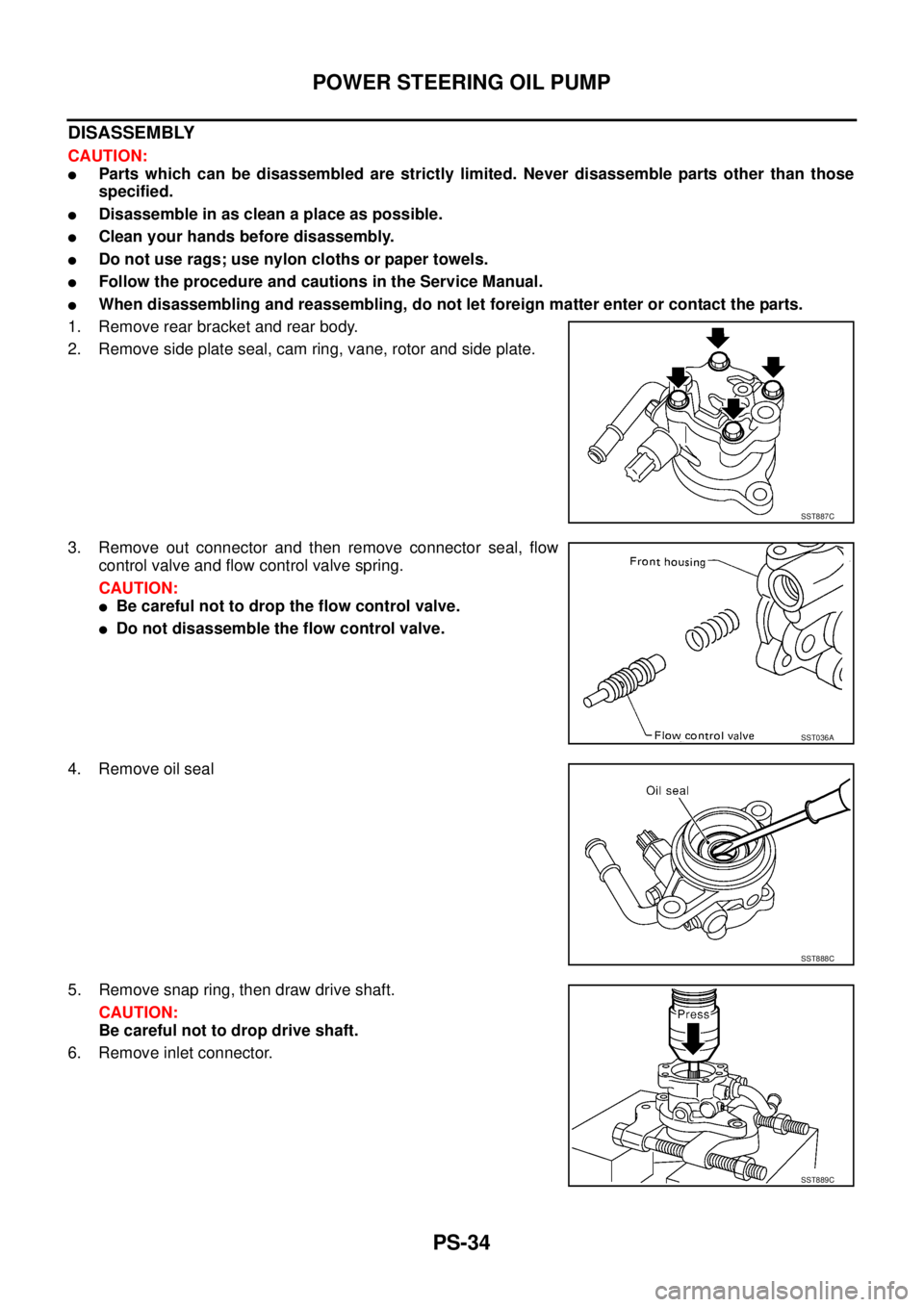
DISASSEMBLY
CAUTION:
�Parts which can be disassembled are strictly limited. Never disassemble parts other than those
specified.
�Disassemble in as clean a place as possible.
�Clean your hands before disassembly.
�Do not use rags; use nylon cloths or paper towels.
�Follow the procedure and cautions in the Service Manual.
�When disassembling and reassembling, do not let foreign matter enter or contact the parts.
1. Remove rear bracket and rear body.
2. Remove side plate seal, cam ring, vane, rotor and side plate.
3. Remove out connector and then remove connector seal, flow
control valve and flow control valve spring.
CAUTION:
�Be careful not to drop the flow control valve.
�Do not disassemble the flow control valve.
4. Remove oil seal
5. Remove snap ring, then draw drive shaft.
CAUTION:
Be careful not to drop drive shaft.
6. Remove inlet connector.
SST887C
SST036A
SST888C
SST889C
 as shown. Install side plate (front) to casing.
5. Install cartridge onto front side pla")
![NISSAN X-TRAIL 2005 Service Repair Manual PS-32
POWER STEERING OIL PUMP
Removal and Installation (YD22DDTi Engine Model)EGS000AI
1. Remove chain case cover.
2. Revolving crank pulley, set sprocket holder [SST].
3. Fix sprocket holder [SST]](/manual-img/5/57403/w960_57403-3493.png "NISSAN X-TRAIL 2005 Service Repair Manual PS-32
POWER STEERING OIL PUMP
Removal and Installation (YD22DDTi Engine Model)EGS000AI
1. Remove chain case cover.
2. Revolving crank pulley, set sprocket holder [SST].
3. Fix sprocket holder [SST]")
EGS000AJ
INSPECTION BEFORE DISASSEMBLY
Disassemble power steering oil pump only when any of fo")