Page 2888 of 4555

PR-6
REAR PROPELLER SHAFT
INSTALLATION
Note the following, and install in the reverse order of removal.
�Align matching marks to install propeller shaft to final drive and transfer companion flanges, and then
tighten to specified torque. Refer to PR-4, "
COMPONENTS"
�When installing center bearing, position bearing cushion overlap
upward as shown in the figure.
�Install center bearing mounting bracket (Lower) with its arrow
mark facing forward.
�Adjust position of mounting bracket sliding back and forth to pre-
vent play in thrust direction of center bearing insulator. Install
bracket to vehicle.
�After assembly, perform a driving test to check propeller shaft
vibration. If vibration occurred, separate propeller shaft from
final drive or transfer. Reinstall companion flange after rotating it
by 90, 180, 270 degrees. Then perform driving test and check
propeller shaft vibration again at each point.
�If propeller shaft or final drive has been replaced, install them as follows;
1. Install propeller shaft while aligning its matching mark A with the
matching mark B on the joint as close as possible.
2. Temporarily tighten bolts and nuts.
3. Press down propeller shaft with matching mark C facing upward.
Then tighten fixing bolts and nuts to the specified torque. Refer
to PR-4, "
COMPONENTS" .
PDIA0422E
PDIA0423E
PDIA0424E
Page 2892 of 4555

RFD-2
PRECAUTIONS
PRECAUTIONSPFP:00001
Service Notice or PrecautionsEDS001YY
�Check for the correct installation status prior to removal or disassembly. If matching marks are required,
be certain they do not interfere with the function of the parts when applied.
�Overhaul should be done in a clean work area, it is preferable to work in dustproof area.
�Before disassembly, using steam or white gasoline, completely remove sand and mud from the exterior of
the unit, preventing them from entering into the unit during disassembly or assembly.
�Check appearance of the disassembled parts for damage, deformation, and unusual wear. Replace them
with a new ones if necessary.
�Gaskets, seals and O-rings should be replaced any time when the unit is disassembled.
�In principle, tighten bolts or nuts gradually in several steps working diagonally from inside to outside. If
tightening sequence is specified, observe it.
�Clean and flush the parts sufficiently and blow-dry them.
�Be careful not to damage sliding surfaces and mating surfaces.
�When applying sealant, remove the old sealant from the mounting surface; then remove any moisture, oil,
and foreign materials from the application and mounting surfaces.
�Always use shop paper for cleaning the inside of components.
�Avoid using cotton gloves or shop rags to prevent entering of lint.
�During assembly, observe the specified tightening torque, and apply new differential oil, petroleum jelly, or
multi-purpose grease as specified for each vehicle, if necessary.
Page 2893 of 4555
PREPARATION
RFD-3
C
E
F
G
H
I
J
K
L
MA
B
RFD
PREPARATIONPFP:00002
Special Service ToolsEDS002VE
Tool number
Tool nameDescription
ST27861000
Drift
a: 62 mm (2.44 in) dia.
b: 52 mm (2.05 in) dia.Installing final drive front oil seal
KV38100200
Drift
a: 65 mm (2.56 in) dia.
b: 49 mm (1.93 in) dia.
�Installing final drive front oil seal
�Installing final drive side oil seal
ST3127S000
Preload gaugeMeasuring preload torque
ST33052000
Drift
a: 22 mm (0.87 in) dia.
b: 28 mm (1.10 in) dia.Removing side bearing inner race
ST33230000
Drift
a: 51 mm (2.01 in) dia.
b: 41 mm (1.61 in) dia.
c: 28.5 mm (1.122 in) dia.Installing pinion front bearing outer race
ST23860000
Drift
a: 38 mm (1.50 in) dia.
b: 33 mm (1.30 in) dia.
�Installing pinion rear bearing inner race
�Installing pinion front bearing inner race
ST35271000
Drift
a: 72 mm (2.83 in) dia.
b: 63 mm (2.48 in) dia.Installing center oil seal
ZZA0832D
ZZA1143D
ZZA0503D
ZZA1023D
ZZA1046D
ZZA0534D
ZZA0814D
Page 2894 of 4555
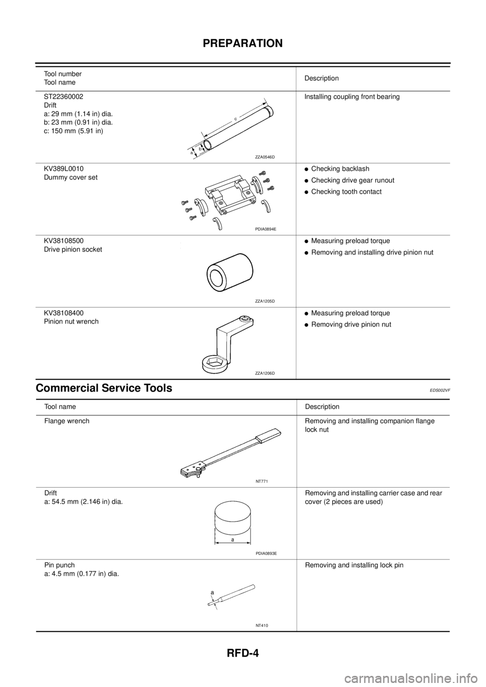
RFD-4
PREPARATION
Commercial Service ToolsEDS002VF
ST22360002
Drift
a: 29 mm (1.14 in) dia.
b: 23 mm (0.91 in) dia.
c: 150 mm (5.91 in)Installing coupling front bearing
KV389L0010
Dummy cover set
�Checking backlash
�Checking drive gear runout
�Checking tooth contact
KV38108500
Drive pinion socket
�Measuring preload torque
�Removing and installing drive pinion nut
KV38108400
Pinion nut wrench
�Measuring preload torque
�Removing drive pinion nut Tool number
Tool nameDescription
ZZA0546D
PDIA0894E
ZZA1205D
ZZA1206D
Tool nameDescription
Flange wrench Removing and installing companion flange
lock nut
Drift
a: 54.5 mm (2.146 in) dia.Removing and installing carrier case and rear
cover (2 pieces are used)
Pin punch
a: 4.5 mm (0.177 in) dia.Removing and installing lock pin
NT771
PDIA0893E
NT410
Page 2898 of 4555

RFD-8
DIFFERENTIAL GEAR OIL
DIFFERENTIAL GEAR OILPFP:KLD30
Changing Differential Gear OilEDS0027G
DRAINING
1. Stop engine.
2. Remove drain plug and drain oil.
3. Set a gasket on drain plug and install it to final drive assembly
and tighten to the specified torque. Refer to RFD-16, "
Compo-
nents" .
CAUTION:
Do not reuse gasket.
FILLING
1. Remove filler plug. Fill with new oil until oil level reaches the
specified level near filler plug mounting hole.
2. After refilling oil, check oil level. Set a gasket to filler plug, then
install it to final drive assembly. Refer to RFD-16, "
Components"
.
CAUTION:
Do not reuse gasket.
Checking Differential Gear OilEDS0027H
OIL LEAKAGE AND OIL LEVEL
�Make sure that oil is not leaking from final drive assembly or around it.
�Check oil level from filler plug mounting hole as shown in the fig-
ure.
CAUTION:
Do not start engine while checking oil level.
�Set a gasket on filler plug and install it on final drive assembly.
Refer to RFD-16, "
Components" .
CAUTION:
Do not reuse gasket.
PDIA0454E
Oil grade and Viscosity:
Refer to MA-17, "
Fluids and Lubricants" .
Oil capacity:
Approx. 0.55 (1 Imp pt)
PDIA0453E
PDIA0453E
Page 2900 of 4555
RFD-10
FRONT OIL SEAL
3. Align the matching mark of electric controlled coupling with the
matching mark of companion flange, then install the companion
flange.
4. Install companion flange lock nut with a flange wrench, tighten
the to the specified torque. Refer to RFD-16, "
Components" .
CAUTION:
Do not reuse companion flange lock nut.
5. Install propeller shaft. Refer to PR-4, "
Removal and Installation"
.
PDIA0455E
Page 2903 of 4555

ELECTRIC CONTROLLED COUPLING
RFD-13
C
E
F
G
H
I
J
K
L
MA
B
RFD
INSTALLATION
1. Install electric controlled coupling to spline of drive pinion inside
carrier case.
CAUTION:
�Align the pin on electric controlled coupling with the
groove of carrier case.
�Be careful not to damage center oil seal.
2. Set 4WD solenoid harness guide to carrier case.
3. Apply liquid gasket to mating surface of coupling cover. Overlap
both ends of the bead for at least 3 mm (0.12 in).
�Use sealant (Three bound 1217 or equivalent).
CAUTION:
Remove old sealant adhering to the mounting surfaces.
Also remove any moisture, oil, or foreign material adhering
to the mounting surfaces.
4. Install coupling cover to carrier case with arrow facing upward,
temporarily tighten reamer bolts to the positions shown in the
figure.
5. Tighten reamer bolts and coupling cover mounting bolts to the
specified torque. Refer to RFD-16, "
Components" .
6. Install electric controlled coupling breather hose to coupling
cover.
7. Install connector bracket and connect 4WD solenoid harness
connector.
8. Install companion flange.
NOTE:
When reusing electric controlled coupling, align the matching
mark of electric controlled coupling with the matching mark of
companion flange, then install companion flange.
9. Install companion flange lock nut with flange wrench, tighten to
the specified torque. Refer to RFD-16, "
Components" .
CAUTION:
Do not reuse companion flange lock nut.
10. Install propeller shaft. Refer to PR-4, "
Removal and Installation"
.
PDIA0912E
PDIA0451E
SDIA0587E
PDIA0455E
Page 2905 of 4555

REAR FINAL DRIVE ASSEMBLY
RFD-15
C
E
F
G
H
I
J
K
L
MA
B
RFD
INSTALLATION
Note the following, and install in the reverse order of removal.
�Refer to RFD-16, "Components" about each tightening torque.
�When installing breather hoses, refer to the figure and following.
CAUTION:
Make sure there are no pinched or restricted areas on the
breather hose caused by bending or winding when install-
ing it.
–For installation of rear final drive breather hose, the vehicle side
end shall be inserted to cross member. Install metal connector
side of this hose to rear cover by inserting it with aiming painted
marking to the front of vehicle.
–For installation of electric controlled coupling breather hose, the
vehicle side end shall be inserted to cross member. Install its
metal tube to rear final drive assembly and direct the metal tube
hose side end to the front of vehicle.
�When oil leaks while removing final drive assembly, check oil
level after the installation. Refer to RFD-8, "
Checking Differential
Gear Oil" .
PDIA0436E
PDIA0437E
 dia.
b: 52 mm (2.05 in) dia.Insta")