Page 2775 of 4555
![NISSAN X-TRAIL 2005 Service Repair Manual ASSEMBLY
AT-511
[ALL]
D
E
F
G
H
I
J
K
L
MA
B
AT
6. Set manual shaft to “P” position to fix idler gear.
7. Tighten idler gear lock nut to the specified torque. Refer to AT-
416, "Components" .
CA](/manual-img/5/57403/w960_57403-2774.png "NISSAN X-TRAIL 2005 Service Repair Manual ASSEMBLY
AT-511
[ALL]
D
E
F
G
H
I
J
K
L
MA
B
AT
6. Set manual shaft to “P” position to fix idler gear.
7. Tighten idler gear lock nut to the specified torque. Refer to AT-
416, \"Components\" .
CA")
ASSEMBLY
AT-511
[ALL]
D
E
F
G
H
I
J
K
L
MA
B
AT
6. Set manual shaft to “P” position to fix idler gear.
7. Tighten idler gear lock nut to the specified torque. Refer to AT-
416, "Components" .
CAUTION:
Lock idler gear with parking pawl when tightening lock nut.
8. Measure turning torque of reduction pinion gear.
�When measuring turning torque, turn reduction pinion
gear in both directions several times to seat bearing roll-
ers correctly.
�If turning torque is out of specification, decrease or
increase the thickness of reduction pinion gear bearing
adjusting shim.
9. After properly adjusting turning torque, clinch idler gear lock nut
as shown.
CAUTION:
Do not reuse idler gear lock nut.
OUTPUT SHAFT END PLAY
�Measure the clearance between side cover and the end of the
output shaft bearing.
�Select proper thickness of output shaft adjusting shim so that
clearance is within specifications.
SAT189F
Turning torque of reduction pinion gear:
0.05 - 0.39 N-m (0.5 - 4.0 kg-cm, 0.43 - 3.47 in-lb)
SAT190FB
SCIA4451E
SAT341D
Page 2777 of 4555
![NISSAN X-TRAIL 2005 Service Repair Manual ASSEMBLY
AT-513
[ALL]
D
E
F
G
H
I
J
K
L
MA
B
AT
6. Select proper thickness of output shaft adjusting shim so that
output shaft end play (clearance between side cover and output
shaft bearing) is wit](/manual-img/5/57403/w960_57403-2776.png "NISSAN X-TRAIL 2005 Service Repair Manual ASSEMBLY
AT-513
[ALL]
D
E
F
G
H
I
J
K
L
MA
B
AT
6. Select proper thickness of output shaft adjusting shim so that
output shaft end play (clearance between side cover and output
shaft bearing) is wit")
ASSEMBLY
AT-513
[ALL]
D
E
F
G
H
I
J
K
L
MA
B
AT
6. Select proper thickness of output shaft adjusting shim so that
output shaft end play (clearance between side cover and output
shaft bearing) is within specifications. Refer to AT- 5 3 8 , "
OUT-
PUT SHAFT ADJUSTING SHIMS" .
7. Install output shaft adjusting shim on output shaft bearing.
Assembly (2)ECS004MF
1. Apply locking sealant (Locktite #518) to transaxle case as
shown in illustration.
2. Fit the mounting part of output shaft bearing on side cover to
output shaft bearing, and after adjusting knock pin position,
install it with light taps using a soft hammer and things like that.
CAUTION:
When installing, to avoid getting damaged and deformed,
set the mounting part straight to parallel with the mounting
surface.
3. Tighten side cover fixing bolts to specified torque. Refer to AT-
416, "Components" .
CAUTION:
�Do not mix bolts A and B.
�Always replace bolts A as they are self-sealing bolts.Output shaft end play (A − B):
0 - 0.15 mm (0 - 0.0059 in)
SAT440D
SCIA4919E
SAT442D
AAT850
Page 2788 of 4555
AT-524
[ALL]
ASSEMBLY
3. Place bearing race selected in total end play adjustment step on
oil pump cover.
CAUTION:
Apply petroleum jelly to bearing race.
4. Place thrust washer selected in reverse clutch end play step on
reverse clutch drum.
CAUTION:
Apply petroleum jelly to thrust washer.
5. Install oil pump assembly and gasket on transaxle case.
CAUTION:
Do not reuse gasket.
6. Tighten oil pump fixing bolts to the specified torque. Refer to AT-
416, "Components"
7. Install O-ring to input shaft assembly (high clutch drum).
CAUTION:
�Apply petroleum jelly to O-ring.
�Do not reuse O-ring.
8. Adjust brake band.
CAUTION:
Do not reuse anchor end pin.
a. Tighten anchor end pin to the specified torque.
b. Back off anchor end pin two and a half turns.
c. While holding anchor end pin, tighten lock nut. Refer to AT- 5 3 5 ,
"BRAKE BAND" .
SCIA3629E
SCIA2980E
SCIA2979E
: 4.9 N·m (0.50 kg-m, 43 in-lb)
SCIA4869E
Page 2789 of 4555
ASSEMBLY
AT-525
[ALL]
D
E
F
G
H
I
J
K
L
MA
B
AT
9. Apply compressed air to oil holes of transaxle case and check
operation of brake band.
10. Install final drive assembly on transaxle case.
11. Install differential lubricant tube on converter housing. Tighten
differential lubricant tube bolts to the specified torque. Refer to
AT- 4 1 6 , "
Components" .
12. Install O-ring on differential oil port of transaxle case.
CAUTION:
�Do not reuse O-ring.
�Apply ATF to O-ring.
13. Install converter housing on transaxle case.
CAUTION:
Apply locking sealant (Locktite #518) to mating surface of
converter housing.
SAT397D
SAT228F
SAT063K
SCIA3281E
SCIA4929E
Page 2790 of 4555
AT-526
[ALL]
ASSEMBLY
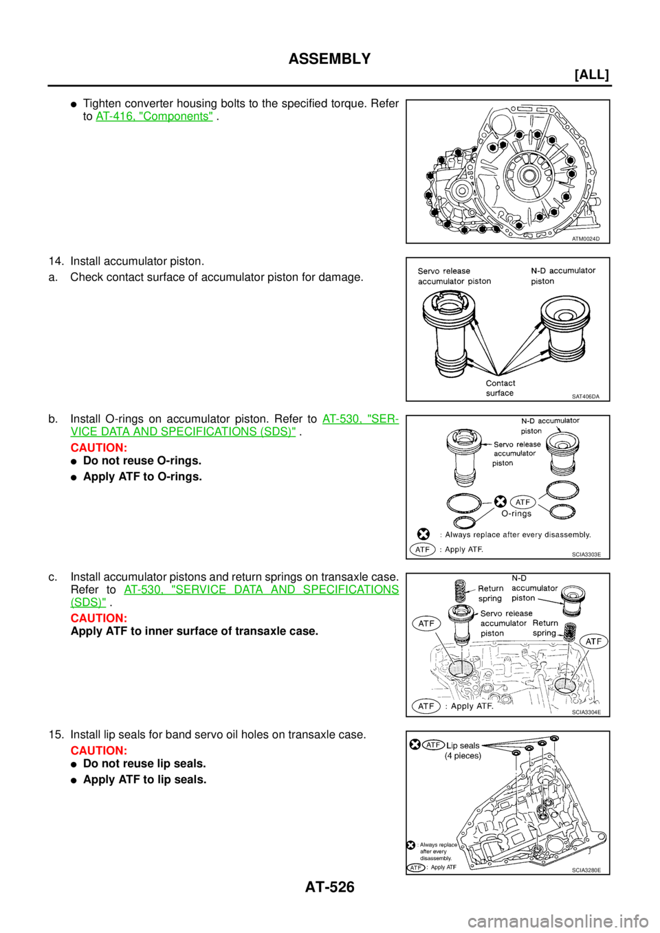
�Tighten converter housing bolts to the specified torque. Refer
to AT- 4 1 6 , "
Components" .
14. Install accumulator piston.
a. Check contact surface of accumulator piston for damage.
b. Install O-rings on accumulator piston. Refer to AT- 5 3 0 , "
SER-
VICE DATA AND SPECIFICATIONS (SDS)" .
CAUTION:
�Do not reuse O-rings.
�Apply ATF to O-rings.
c. Install accumulator pistons and return springs on transaxle case.
Refer to AT- 5 3 0 , "
SERVICE DATA AND SPECIFICATIONS
(SDS)" .
CAUTION:
Apply ATF to inner surface of transaxle case.
15. Install lip seals for band servo oil holes on transaxle case.
CAUTION:
�Do not reuse lip seals.
�Apply ATF to lip seals.
ATM0024D
SAT406DA
SCIA3303E
SCIA3304E
SCIA3280E
Page 2791 of 4555
ASSEMBLY
AT-527
[ALL]
D
E
F
G
H
I
J
K
L
MA
B
AT
16. Install low & reverse brake tube and oil sleeve. Tighten Low &
reverse brake tube bolts to the specified torque. Refer to AT-
416, "Components" .
CAUTION:
�Do not reuse oil sleeve.
�Apply ATF to oil sleeve.
17. Install control valve assembly.
a. Install O-ring to terminal body.
CAUTION:
�Do not reuse O-ring.
�Apply ATF to O-ring.
b. Insert manual valve into control valve assembly.
CAUTION:
Apply ATF to manual valve.
c. Set manual shaft in Neutral position.
d. Install control valve assembly on transaxle case while aligning
manual valve with manual plate.
e. Pass terminal cord assembly through transaxle case and install
terminal body on transaxle case by pushing it.
f. Install snap ring to terminal body.
CAUTION:
Do not expand snap ring excessively.
SCIA4868E
SAT005F
SAT094J
SCIA4866E
Page 2792 of 4555
![NISSAN X-TRAIL 2005 Service Repair Manual AT-528
[ALL]
ASSEMBLY
g. Tighten control valve assembly fixing bolts A , B and C to the specified torque. Refer to AT- 4 1 6 , "Compo-
nents" .
Bolt length, number and location:
CAUTION:
�Do not](/manual-img/5/57403/w960_57403-2791.png "NISSAN X-TRAIL 2005 Service Repair Manual AT-528
[ALL]
ASSEMBLY
g. Tighten control valve assembly fixing bolts A , B and C to the specified torque. Refer to AT- 4 1 6 , \"Compo-
nents\" .
Bolt length, number and location:
CAUTION:
�Do not")
AT-528
[ALL]
ASSEMBLY
g. Tighten control valve assembly fixing bolts A , B and C to the specified torque. Refer to AT- 4 1 6 , "Compo-
nents" .
Bolt length, number and location:
CAUTION:
�Do not reuse idler gear bearing.
�Apply ATF to idler gear bearing.
18. Install PNP switch.
a. Set manual shaft in “P” position.
b. Temporarily install PNP switch on manual shaft.
c. Move manual shaft to “N” position.
d. Use a 3 mm (0.12 in) pin for this adjustment.
i. Insert the pin straight into the manual shaft adjustment hole.
ii. Rotate PNP switch until the pin can also be inserted straight into
hole in PNP switch.
e. Tighten PNP switch fitting bolts. Refer to AT- 4 1 6 , "
Components"
.
f. Remove pin from adjustment hole after adjusting PNP switch.
19. Install bracket on transaxle case.
20. Install O-ring on revolution sensor.
CAUTION:
�Do not reuse O-ring.
�Apply petroleum jelly to O-ring.
21. Install revolution sensor on transaxle case.
Bolt symbol A B C
Bolt length “ ” mm (in)
40.0 mm
(1.575 in)33.0 mm
(1.299 in)43.5 mm
(1.713 in)
Number of bolts 5 6 2
AAT260A
SCIA3154E
SCIA4930E
Page 2793 of 4555
ASSEMBLY
AT-529
[ALL]
D
E
F
G
H
I
J
K
L
MA
B
AT
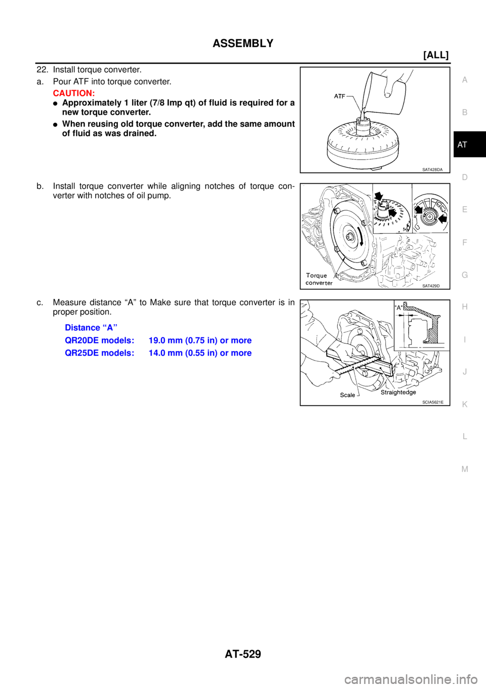
22. Install torque converter.
a. Pour ATF into torque converter.
CAUTION:
�Approximately 1 liter (7/8 Imp qt) of fluid is required for a
new torque converter.
�When reusing old torque converter, add the same amount
of fluid as was drained.
b. Install torque converter while aligning notches of torque con-
verter with notches of oil pump.
c. Measure distance “A” to Make sure that torque converter is in
proper position.
SAT428DA
SAT429D
Distance “A”
QR20DE models: 19.0 mm (0.75 in) or more
QR25DE models: 14.0 mm (0.55 in) or more
SCIA5621E
![NISSAN X-TRAIL 2005 Service Repair Manual AT-524
[ALL]
ASSEMBLY
3. Place bearing race selected in total end play adjustment step on
oil pump cover.
CAUTION:
Apply petroleum jelly to bearing race.
4. Place thrust washer selected in reverse c](/manual-img/5/57403/w960_57403-2787.png "NISSAN X-TRAIL 2005 Service Repair Manual AT-524
[ALL]
ASSEMBLY
3. Place bearing race selected in total end play adjustment step on
oil pump cover.
CAUTION:
Apply petroleum jelly to bearing race.
4. Place thrust washer selected in reverse c")
![NISSAN X-TRAIL 2005 Service Repair Manual ASSEMBLY
AT-525
[ALL]
D
E
F
G
H
I
J
K
L
MA
B
AT
9. Apply compressed air to oil holes of transaxle case and check
operation of brake band.
10. Install final drive assembly on transaxle case.
11. Inst](/manual-img/5/57403/w960_57403-2788.png "NISSAN X-TRAIL 2005 Service Repair Manual ASSEMBLY
AT-525
[ALL]
D
E
F
G
H
I
J
K
L
MA
B
AT
9. Apply compressed air to oil holes of transaxle case and check
operation of brake band.
10. Install final drive assembly on transaxle case.
11. Inst")
![NISSAN X-TRAIL 2005 Service Repair Manual ASSEMBLY
AT-527
[ALL]
D
E
F
G
H
I
J
K
L
MA
B
AT
16. Install low & reverse brake tube and oil sleeve. Tighten Low &
reverse brake tube bolts to the specified torque. Refer to AT-
416, "Components" .](/manual-img/5/57403/w960_57403-2790.png "NISSAN X-TRAIL 2005 Service Repair Manual ASSEMBLY
AT-527
[ALL]
D
E
F
G
H
I
J
K
L
MA
B
AT
16. Install low & reverse brake tube and oil sleeve. Tighten Low &
reverse brake tube bolts to the specified torque. Refer to AT-
416, \"Components\" .")