Page 2719 of 4555
REPAIR FOR COMPONENT PARTS
AT-455
[ALL]
D
E
F
G
H
I
J
K
L
MA
B
AT
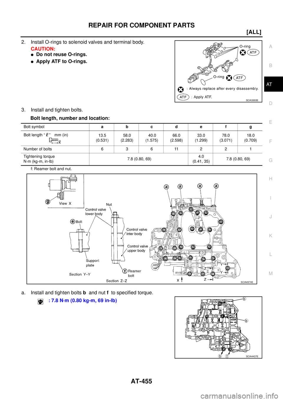
2. Install O-rings to solenoid valves and terminal body.
CAUTION:
�Do not reuse O-rings.
�Apply ATF to O-rings.
3. Install and tighten bolts.
Bolt length, number and location:
f: Reamer bolt and nut.
a. Install and tighten bolts b and nut f to specified torque.
SCIA3693E
Bolt symbolabcde f g
Bolt length “ ” mm (in)
13.5
(0.531)58.0
(2.283) 40.0
(1.575)66.0
(2.598)33.0
(1.299)78.0
(3.071)18.0
(0.709)
Number of bolts 6 3 6 11 2 2 1
Tightening torque
N·m (kg-m, in-lb)7.8 (0.80, 69)4.0
(0.41, 35)7.8 (0.80, 69)
SCIA4974E
: 7.8 N·m (0.80 kg-m, 69 in-lb)
SCIA4437E
Page 2720 of 4555
AT-456
[ALL]
REPAIR FOR COMPONENT PARTS
b. Install solenoid valve assembly and line pressure solenoid valve
on control valve assembly.
c. Tighten bolts a , c and g to specified torque.
d. Set oil strainer, then tighten bolts a , d and nut f to specified
torque.
e. Tighten bolts e to specified torque. : 7.8 N·m (0.80 kg-m, 69 in-lb)
SCIA4438E
: 7.8 N·m (0.80 kg-m, 69 in-lb)
SCIA3484E
: 4.0 N·m (0.41 kg-m, 35 in-lb)
SCIA3487E
Page 2722 of 4555
![NISSAN X-TRAIL 2005 Service Repair Manual AT-458
[ALL]
REPAIR FOR COMPONENT PARTS
DISASSEMBLY
1. Remove valves at retainer plates.
CAUTION:
Do not use a magnetic pick-up tool.
a. Use a screwdriver to remove retainer plates.
b. Remove retain](/manual-img/5/57403/w960_57403-2721.png "NISSAN X-TRAIL 2005 Service Repair Manual AT-458
[ALL]
REPAIR FOR COMPONENT PARTS
DISASSEMBLY
1. Remove valves at retainer plates.
CAUTION:
Do not use a magnetic pick-up tool.
a. Use a screwdriver to remove retainer plates.
b. Remove retain")
AT-458
[ALL]
REPAIR FOR COMPONENT PARTS
DISASSEMBLY
1. Remove valves at retainer plates.
CAUTION:
Do not use a magnetic pick-up tool.
a. Use a screwdriver to remove retainer plates.
b. Remove retainer plates while holding spring, plugs or sleeves.
CAUTION:
Remove plugs slowly to prevent internal parts from jumping
out.
1. Retainer plate 2. Plug 3. Cooler check valve spring
4. Cooler check valve 5. Control valve upper body 6. Pilot valve
7. Pilot valve spring 8. Retainer plate 9. 1-2 accumulator retainer plate
10. 1-2 accumulator piston spring 11. 1-2 accumulator piston 12. Plug
13. Retainer plate 14. Retainer plate 15. Plug
16. 1st reducing valve 17. 1st reducing valve spring 18. Retainer plate
19. 3-2 timing valve spring 20. 3-2 timing valve 21. Retainer plate
22. Plug 23. Overrun clutch reducing valve 24. Overrun clutch reducing valve spring
25. Retainer plate 26. Torque converter relief valve spring 27. Torque converter relief valve
28. Retainer plate 29. Sleeve 30. Plug
31. Torque converter clutch control valve
spring32. Torque converter clutch control
valve33. Retainer plate
34. Plug 35. 1-2 accumulator valve spring 36. 1-2 accumulator valve
SCIA4979E
SAT553G
SAT554G
Page 2724 of 4555
![NISSAN X-TRAIL 2005 Service Repair Manual AT-460
[ALL]
REPAIR FOR COMPONENT PARTS
–Wrap a small screwdriver with vinyl tape and use it to insert
valves into their proper positions.
1-2 Accumulator Valve
�Install 1-2 accumulator valve. Ali](/manual-img/5/57403/w960_57403-2723.png "NISSAN X-TRAIL 2005 Service Repair Manual AT-460
[ALL]
REPAIR FOR COMPONENT PARTS
–Wrap a small screwdriver with vinyl tape and use it to insert
valves into their proper positions.
1-2 Accumulator Valve
�Install 1-2 accumulator valve. Ali")
AT-460
[ALL]
REPAIR FOR COMPONENT PARTS
–Wrap a small screwdriver with vinyl tape and use it to insert
valves into their proper positions.
1-2 Accumulator Valve
�Install 1-2 accumulator valve. Align 1-2 accumulator retainer
plate from opposite side of control valve body.
�Install 1-2 accumulator piston spring, 1-2 accumulator valve
spring, 1-2 accumulator piston and plugs.
�Install retainer plates.
–While pushing plugs (with 1-2 accumulator piston spring and 1-2
accumulator valve spring), install retainer plate.
Retainer Plate (Control Valve Upper Body)
Unit: mm (in)
�Install proper retainer plates.
Refer to AT- 4 5 7 , "
Control Valve Upper Body" .
SAT141D
SCIA5638E
SAT143D
Loca
tionName of control valve Width A Length B
L14 Pilot valve
6.0 (0.236)21.5 (0.846) L16 1st reducing valve
L17 3-2 timing valve
L19 Torque converter relief valve
L151-2 accumulator valve
40.5 (1.594)
1-2 accumulator piston
L18 Overrun clutch reducing valve
24.0 (0.945)
L21 Cooler check valve
L20 Torque converter clutch control valve 28.0 (1.102)
SAT086F
Page 2770 of 4555
AT-506
[ALL]
REPAIR FOR COMPONENT PARTS
b. Move side gear up and down to measure dial indicator deflec-
tion. Always measure indicator deflection on both side gears.
c. If not within specification, adjust the clearance by changing the
thickness of differential side gear thrust washers. Refer to AT-
535, "Final Drive" .
4. Install lock pin.
CAUTION:
�Do not reuse lock pin.
�Make sure that lock pin is flush with case.
5. Press on differential side bearings.
CAUTION:
Apply ATF to differential side bearings.
6. Install differential side bearing outer race and differential side
bearing adjusting shim on transaxle case. Refer to AT- 5 0 8 ,
"Adjustment (1)" .
7. Tighten final gear and tighten fixing bolts to the specified torque
in numerical order shown in the figure after temporarily tighten-
ing them. Refer to AT- 5 0 3 , "
COMPONENTS" . Clearance between side gear and differential case
with washer:
0.1 - 0.2 mm (0.004 - 0.008 in)
SMT611A
SMT699BA
SAT545FA
ATM0432D
Page 2771 of 4555
ASSEMBLY
AT-507
[ALL]
D
E
F
G
H
I
J
K
L
MA
B
AT
ASSEMBLYPFP:00000
Assembly (1)ECS004MD
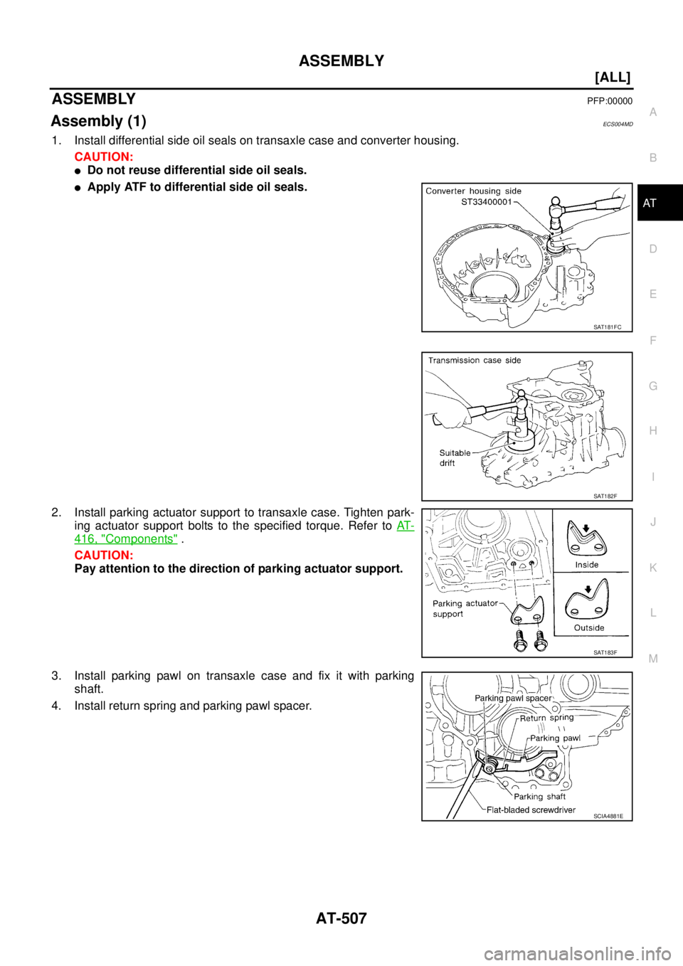
1. Install differential side oil seals on transaxle case and converter housing.
CAUTION:
�Do not reuse differential side oil seals.
�Apply ATF to differential side oil seals.
2. Install parking actuator support to transaxle case. Tighten park-
ing actuator support bolts to the specified torque. Refer to AT-
416, "Components" .
CAUTION:
Pay attention to the direction of parking actuator support.
3. Install parking pawl on transaxle case and fix it with parking
shaft.
4. Install return spring and parking pawl spacer.
SAT181FC
SAT182F
SAT183F
SCIA4881E
Page 2772 of 4555
![NISSAN X-TRAIL 2005 Service Repair Manual AT-508
[ALL]
ASSEMBLY
Adjustment (1)ECS004ME
DIFFERENTIAL SIDE BEARING PRELOAD
1. Install differential side bearing outer race without differential side
bearing adjusting shim on transaxle case.
CAU](/manual-img/5/57403/w960_57403-2771.png "NISSAN X-TRAIL 2005 Service Repair Manual AT-508
[ALL]
ASSEMBLY
Adjustment (1)ECS004ME
DIFFERENTIAL SIDE BEARING PRELOAD
1. Install differential side bearing outer race without differential side
bearing adjusting shim on transaxle case.
CAU")
AT-508
[ALL]
ASSEMBLY
Adjustment (1)ECS004ME
DIFFERENTIAL SIDE BEARING PRELOAD
1. Install differential side bearing outer race without differential side
bearing adjusting shim on transaxle case.
CAUTION:
Apply ATF to differential side bearing outer race.
2. Install differential side bearing outer race on converter housing.
CAUTION:
Apply ATF to differential side bearing outer race.
3. Place final drive assembly on transaxle case.
4. Install transaxle case on converter housing. Tighten transaxle
case fixing bolts to the specified torque. Refer to AT- 4 1 6 , "
Com-
ponents" .
5. Attach dial indicator on differential case at converter housing
side.
6. Insert Tool into differential side gear from transaxle case side.
7. Move SST up and down and measure dial indicator deflection.
8. Select proper thickness of differential side bearing adjusting
shim(s). Refer to AT- 5 3 6 , "
DIFFERENTIAL SIDE BEARING
PRELOAD ADJUSTING SHIMS" .
Suitable shim thickness = Dial indicator deflection + Speci-
fied bearing preload
SAT870D
ATM0024D
Bearing preload:
0.05 - 0.09 mm (0.0020 - 0.0035 in)
SAT186FA
Page 2773 of 4555
![NISSAN X-TRAIL 2005 Service Repair Manual ASSEMBLY
AT-509
[ALL]
D
E
F
G
H
I
J
K
L
MA
B
AT
9. Remove converter housing from transaxle case.
10. Remove final drive assembly from transaxle case.
11. Remove differential side bearing outer race](/manual-img/5/57403/w960_57403-2772.png "NISSAN X-TRAIL 2005 Service Repair Manual ASSEMBLY
AT-509
[ALL]
D
E
F
G
H
I
J
K
L
MA
B
AT
9. Remove converter housing from transaxle case.
10. Remove final drive assembly from transaxle case.
11. Remove differential side bearing outer race")
ASSEMBLY
AT-509
[ALL]
D
E
F
G
H
I
J
K
L
MA
B
AT
9. Remove converter housing from transaxle case.
10. Remove final drive assembly from transaxle case.
11. Remove differential side bearing outer race from transaxle case.
12. Reinstall differential side bearing outer race and differential side
bearing adjusting shim selected from SDS table on transaxle
case. Refer to AT- 5 3 6 , "
DIFFERENTIAL SIDE BEARING PRE-
LOAD ADJUSTING SHIMS" .
13. Reinstall converter housing on transaxle case and tighten con-
verter housing mounting bolts to the specified torque. Refer to
AT- 4 1 6 , "
Components" .
14. Insert SST and measure turning torque of final drive assembly.
�Turn final drive assembly in both directions several times
to seat bearing rollers correctly.
�When old bearing is used again, turning torque will be
slightly less than the above.
�Make sure torque is close to the specified range.
REDUCTION PINION GEAR BEARING PRELOAD
1. Remove converter housing and final drive assembly from tran-
saxle case.
2. Select proper thickness of reduction pinion gear adjusting shim
using the following procedures.
a. Place reduction pinion gear on transaxle case as shown.
b. Place idler gear bearing on transaxle case.
c. Measure the dimensions “B” “C” and “D” and calculate dimen-
sion “A”.
SAT010FC
Turning torque of final drive assembly (New bearing):
0.78 - 1.37 N-m (0.8 - 14.0 kg-cm, 6.9 - 12.2 in-lb)
Preload adapter: KV38105210
SAT188FA
SAT332DA
A = D − (B + C)
“A”: Distance between the surface of idler gear bear-
ing inner race and the adjusting shim mating
surface of reduction pinion gear.
SAT333DA
![NISSAN X-TRAIL 2005 Service Repair Manual AT-456
[ALL]
REPAIR FOR COMPONENT PARTS
b. Install solenoid valve assembly and line pressure solenoid valve
on control valve assembly.
c. Tighten bolts a , c and g to specified torque.
d. Set oil](/manual-img/5/57403/w960_57403-2719.png "NISSAN X-TRAIL 2005 Service Repair Manual AT-456
[ALL]
REPAIR FOR COMPONENT PARTS
b. Install solenoid valve assembly and line pressure solenoid valve
on control valve assembly.
c. Tighten bolts a , c and g to specified torque.
d. Set oil")
![NISSAN X-TRAIL 2005 Service Repair Manual AT-506
[ALL]
REPAIR FOR COMPONENT PARTS
b. Move side gear up and down to measure dial indicator deflec-
tion. Always measure indicator deflection on both side gears.
c. If not within specification,](/manual-img/5/57403/w960_57403-2769.png "NISSAN X-TRAIL 2005 Service Repair Manual AT-506
[ALL]
REPAIR FOR COMPONENT PARTS
b. Move side gear up and down to measure dial indicator deflec-
tion. Always measure indicator deflection on both side gears.
c. If not within specification,")