Page 2637 of 4555
TORQUE CONVERTER CLUTCH SOLENOID VALVE
AT-373
[ALL]
D
E
F
G
H
I
J
K
L
MA
B
AT
6. CHECK TCM
1. Check TCM input/output signal. Refer to AT- 9 4 , "
TCM Terminals and Reference Value" .
2. If NG, recheck TCM pin terminals for damage or loose connection with harness connector.
OK or NG
OK >>INSPECTION END
NG >> Repair or replace damaged parts.
Component InspectionECS004U7
TORQUE CONVERTER CLUTCH SOLENOID VALVE
�For removal, refer to AT- 4 0 4 , "Control Valve Assembly and Accumulators" .
Resistance Check
�Check resistance between two terminal 5 and ground.
Operation Check
�Check solenoid valve by listening for its operating sound while
applying battery voltage to the terminal and ground.
Solenoid valve Terminal No.Resistance
(Approx.)
Torque converter
clutch solenoid
valve5 Ground 5 - 20Ω
SCIA2063E
SCIA2066E
Page 2678 of 4555
AT-414
[ALL]
REMOVAL AND INSTALLATION
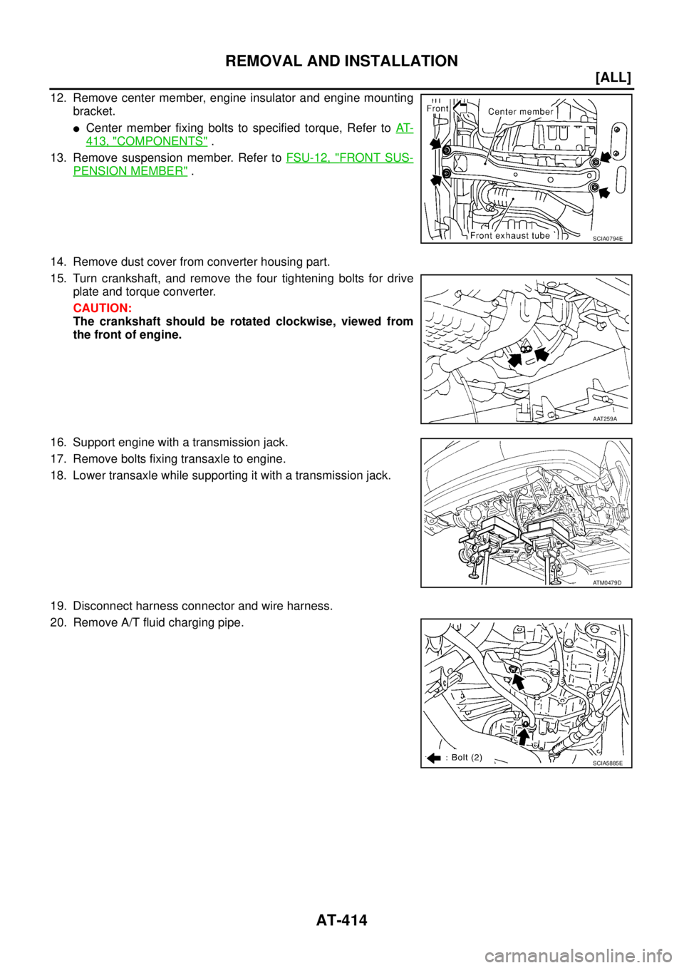
12. Remove center member, engine insulator and engine mounting
bracket.
�Center member fixing bolts to specified torque, Refer to AT-
413, "COMPONENTS" .
13. Remove suspension member. Refer to FSU-12, "
FRONT SUS-
PENSION MEMBER" .
14. Remove dust cover from converter housing part.
15. Turn crankshaft, and remove the four tightening bolts for drive
plate and torque converter.
CAUTION:
The crankshaft should be rotated clockwise, viewed from
the front of engine.
16. Support engine with a transmission jack.
17. Remove bolts fixing transaxle to engine.
18. Lower transaxle while supporting it with a transmission jack.
19. Disconnect harness connector and wire harness.
20. Remove A/T fluid charging pipe.
SCIA0794E
AAT259A
ATM0479D
SCIA5885E
Page 2679 of 4555
![NISSAN X-TRAIL 2005 Service Repair Manual REMOVAL AND INSTALLATION
AT-415
[ALL]
D
E
F
G
H
I
J
K
L
MA
B
AT
21. Remove fluid cooler tube.
INSPECTION
Installation and inspection of torque converter
� After inserting a torque converter to a tra](/manual-img/5/57403/w960_57403-2678.png "NISSAN X-TRAIL 2005 Service Repair Manual REMOVAL AND INSTALLATION
AT-415
[ALL]
D
E
F
G
H
I
J
K
L
MA
B
AT
21. Remove fluid cooler tube.
INSPECTION
Installation and inspection of torque converter
� After inserting a torque converter to a tra")
REMOVAL AND INSTALLATION
AT-415
[ALL]
D
E
F
G
H
I
J
K
L
MA
B
AT
21. Remove fluid cooler tube.
INSPECTION
Installation and inspection of torque converter
� After inserting a torque converter to a transaxle, be sure to
check distance “A” to ensure it is within the reference value limit.
InstallationECS004ND
Install the removed parts in the reverse order of the removal, while paying attention to the following work.
�When installing transaxle to the engine, attach the fixing bolts in
accordance with the following standard.
�Align the positions of tightening bolts for drive plate with those of
the torque converter, and temporarily tighten the bolts. Then,
tighten the bolts to the specified torque. Refer to AT- 4 1 6 , "
Com-
ponents" .
CAUTION:
�When turning crankshaft, turn it clockwise as viewed from
the front of the engine.
�When tightening the tightening bolts for the torque con-
verter after fixing the crankshaft pulley bolts, be sure to
confirm the tightening torque of the crankshaft pulley
mounting bolts.
� After converter is installed to drive plate, rotate crankshaft
several turns and check to be sure that transaxle rotates freely without binding.
�After completing installation, check for fluid leakage, fluid level, and the positions of A/T. Refer to AT- 1 6 ,
"Checking A/T Fluid" , AT- 4 0 9 , "CONTROL CABLE ADJUSTMENT" .
SCIA2596E
Distance “A”
QR20DE models: 19.0 mm (0.75 in) or more
QR25DE models: 14.0 mm (0.55 in) or more
SAT573D
Bolt No.Tightening torque
N·m (kg-m, ft-lb)Bolt length “ L ”
mm (in)
1
75 (7.7, 55)49 (1.93)
2 45 (1.77)
3
43 (4.4, 32)40 (1.57)
4 30 (1.18)
5
36 (3.7, 27)40 (1.57)
6 45 (1.97)
SCIA0795E
SCIA3138E
Page 2681 of 4555
OVERHAUL
AT-417
[ALL]
D
E
F
G
H
I
J
K
L
MA
B
AT
1. Differential side bearing 2. Pinion mate gear thrust washer 3. Pinion mate gear
4. Pinion mate shaft 5. Lock pin 6. Side gear
7. Side gear thrust washer 8. Differential side bearing 9. Differential case
10. Final gear 11. Differential side bearing adjusting
shim12. RH differential side oil seal
13. Torque converter 14. Converter housing 15. Differential lubricant tube
16. Clip 17. O-ring 18. Oil pump housing oil seal
19. Oil pump housing 20. O-ring 21. Outer gear
22. Inner gear 23. Oil pump cover 24. Oil pump assembly
25. Seal ring 26. Gasket
Page 2688 of 4555
AT-424
[ALL]
DISASSEMBLY
DISASSEMBLYPFP:31020
DisassemblyECS004LZ
1. Drain ATF through drain plug.
2. Remove torque converter.
3. Check torque converter one-way clutch using check tool as
shown in the right figure.
a. Insert check tool into the groove of bearing support built into
one-way clutch outer race.
b. When fixing bearing support with check tool, rotate one- way
clutch spline using screwdriver.
c. Check that inner race rotates clockwise only. If not, replace
torque converter assembly.
SCIA0003E
SAT008D
SAT009D
Page 2706 of 4555
AT-442
[ALL]
REPAIR FOR COMPONENT PARTS
3. Install manual shaft and manual plate.
4. Install parking rod plate (with parking rod) on manual shaft.
5. Align groove of manual shaft and hole of transaxle case.
6. Install manual shaft retaining pin up to bottom of hole.
CAUTION:
Do not reuse retaining pin.
7. Set parking rod plate onto manual shaft and drive retaining pin.
CAUTION:
�Both ends of pin should protrude.
�Do not reuse retaining pin.
8. Install manual plate retaining pin.
CAUTION:
�Both ends of pin should protrude.
�Do not reuse retaining pin.
9. Install detente spring on transaxle case. Tighten detente spring
fitting bolt to the specified torque. Refer to AT- 4 4 0 , "
COMPO-
NENTS" .
SCIA3627E
SAT045FC
SAT034JA
SAT047FC
SAT042F
Page 2710 of 4555
AT-446
[ALL]
REPAIR FOR COMPONENT PARTS
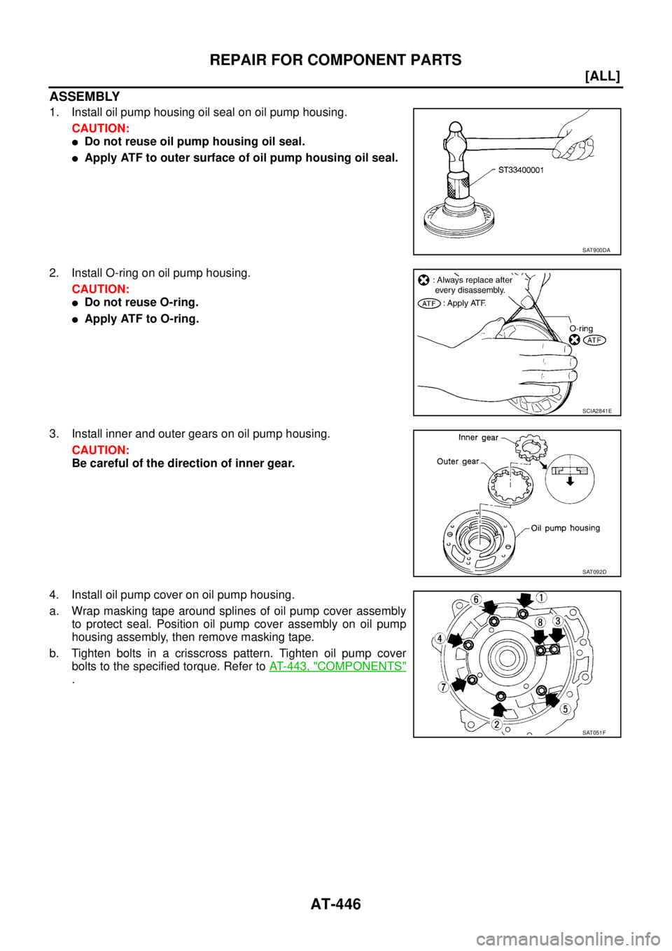
ASSEMBLY
1. Install oil pump housing oil seal on oil pump housing.
CAUTION:
�Do not reuse oil pump housing oil seal.
�Apply ATF to outer surface of oil pump housing oil seal.
2. Install O-ring on oil pump housing.
CAUTION:
�Do not reuse O-ring.
�Apply ATF to O-ring.
3. Install inner and outer gears on oil pump housing.
CAUTION:
Be careful of the direction of inner gear.
4. Install oil pump cover on oil pump housing.
a. Wrap masking tape around splines of oil pump cover assembly
to protect seal. Position oil pump cover assembly on oil pump
housing assembly, then remove masking tape.
b. Tighten bolts in a crisscross pattern. Tighten oil pump cover
bolts to the specified torque. Refer to AT- 4 4 3 , "
COMPONENTS"
.
SAT900DA
SCIA2841E
SAT092D
SAT051F
Page 2716 of 4555
![NISSAN X-TRAIL 2005 Service Repair Manual AT-452
[ALL]
REPAIR FOR COMPONENT PARTS
�Check to see that retainer plates are properly positioned in con-
trol valve upper body.
Oil Strainer
�Check wire netting of oil strainer for damage.
Shift S](/manual-img/5/57403/w960_57403-2715.png "NISSAN X-TRAIL 2005 Service Repair Manual AT-452
[ALL]
REPAIR FOR COMPONENT PARTS
�Check to see that retainer plates are properly positioned in con-
trol valve upper body.
Oil Strainer
�Check wire netting of oil strainer for damage.
Shift S")
AT-452
[ALL]
REPAIR FOR COMPONENT PARTS
�Check to see that retainer plates are properly positioned in con-
trol valve upper body.
Oil Strainer
�Check wire netting of oil strainer for damage.
Shift Solenoid Valves “A” and “B”, Line Pressure Solenoid Valve, Torque Converter Clutch
Solenoid Valve and Overrun Clutch Solenoid Valve
�Measure resistance.
�Except for EURO-OBD:
�For shift solenoid valve A, refer to AT- 3 5 0 , "SHIFT SOLENOID
VALVE A" .
�For shift solenoid valve B, refer to AT- 3 5 6 , "SHIFT SOLENOID
VALVE B" .
�For line pressure solenoid valve, refer to AT- 3 8 7 , "LINE PRES-
SURE SOLENOID VALVE" .
�For torque converter clutch solenoid valve, refer to AT- 3 6 8 ,
"TORQUE CONVERTER CLUTCH SOLENOID VALVE" .
�For overrun clutch solenoid valve, refer to AT- 3 6 2 , "OVERRUN
CLUTCH SOLENOID VALVE" .
�For A/T fluid temperature sensor, refer toAT-374, "BATT/FLUID TEMP SEN (A/T FLUID TEMP SENSOR
CIRCUIT AND TCM POWER SOURCE)" .
�EURO-OBD:
�For shift solenoid valve A, refer to AT- 1 6 1 , "DTC P0750 SHIFT SOLENOID VALVE A" .
�For shift solenoid valve B, refer to AT- 1 6 7 , "DTC P0755 SHIFT SOLENOID VALVE B" .
�For line pressure solenoid valve, refer to AT- 1 5 4 , "DTC P0745 LINE PRESSURE SOLENOID VALVE" .
�For torque converter clutch solenoid valve, refer to AT- 1 4 8 , "DTC P0740 TORQUE CONVERTER
CLUTCH SOLENOID VALVE" .
�For overrun clutch solenoid valve, refer to AT- 1 7 8 , "DTC P1760 OVERRUN CLUTCH SOLENOID VALVE"
.
�For A/T fluid temperature sensor, refer to AT- 1 8 4 , "DTC BATT/FLUID TEMP SEN (A/T FLUID TEMP SEN-
SOR CIRCUIT AND TCM POWER SOURCE)" .
SCIA4979E
SCIA3291E
SCIA0805E
![NISSAN X-TRAIL 2005 Service Repair Manual TORQUE CONVERTER CLUTCH SOLENOID VALVE
AT-373
[ALL]
D
E
F
G
H
I
J
K
L
MA
B
AT
6. CHECK TCM
1. Check TCM input/output signal. Refer to AT- 9 4 , "
TCM Terminals and Reference Value" .
2. If NG, rech](/manual-img/5/57403/w960_57403-2636.png "NISSAN X-TRAIL 2005 Service Repair Manual TORQUE CONVERTER CLUTCH SOLENOID VALVE
AT-373
[ALL]
D
E
F
G
H
I
J
K
L
MA
B
AT
6. CHECK TCM
1. Check TCM input/output signal. Refer to AT- 9 4 , \"
TCM Terminals and Reference Value\" .
2. If NG, rech")
![NISSAN X-TRAIL 2005 Service Repair Manual OVERHAUL
AT-417
[ALL]
D
E
F
G
H
I
J
K
L
MA
B
AT
1. Differential side bearing 2. Pinion mate gear thrust washer 3. Pinion mate gear
4. Pinion mate shaft 5. Lock pin 6. Side gear
7. Side gear thrust w](/manual-img/5/57403/w960_57403-2680.png "NISSAN X-TRAIL 2005 Service Repair Manual OVERHAUL
AT-417
[ALL]
D
E
F
G
H
I
J
K
L
MA
B
AT
1. Differential side bearing 2. Pinion mate gear thrust washer 3. Pinion mate gear
4. Pinion mate shaft 5. Lock pin 6. Side gear
7. Side gear thrust w")
![NISSAN X-TRAIL 2005 Service Repair Manual AT-424
[ALL]
DISASSEMBLY
DISASSEMBLYPFP:31020
DisassemblyECS004LZ
1. Drain ATF through drain plug.
2. Remove torque converter.
3. Check torque converter one-way clutch using check tool as
shown in t](/manual-img/5/57403/w960_57403-2687.png "NISSAN X-TRAIL 2005 Service Repair Manual AT-424
[ALL]
DISASSEMBLY
DISASSEMBLYPFP:31020
DisassemblyECS004LZ
1. Drain ATF through drain plug.
2. Remove torque converter.
3. Check torque converter one-way clutch using check tool as
shown in t")
![NISSAN X-TRAIL 2005 Service Repair Manual AT-442
[ALL]
REPAIR FOR COMPONENT PARTS
3. Install manual shaft and manual plate.
4. Install parking rod plate (with parking rod) on manual shaft.
5. Align groove of manual shaft and hole of transax](/manual-img/5/57403/w960_57403-2705.png "NISSAN X-TRAIL 2005 Service Repair Manual AT-442
[ALL]
REPAIR FOR COMPONENT PARTS
3. Install manual shaft and manual plate.
4. Install parking rod plate (with parking rod) on manual shaft.
5. Align groove of manual shaft and hole of transax")