Page 3240 of 4555
ATC-62
TROUBLE DIAGNOSIS
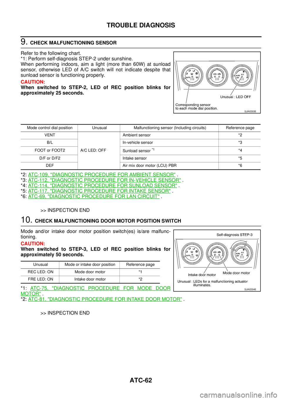
9. CHECK MALFUNCTIONING SENSOR
Refer to the following chart.
*1: Perform self-diagnosis STEP-2 under sunshine.
When performing indoors, aim a light (more than 60W) at sunload
sensor, otherwise LED of A/C switch will not indicate despite that
sunload sensor is functioning properly.
CAUTION:
When switched to STEP-2, LED of REC position blinks for
approximately 25 seconds.
*2: ATC-109, "
DIAGNOSTIC PROCEDURE FOR AMBIENT SENSOR" .
*3: AT C - 11 2 , "
DIAGNOSTIC PROCEDURE FOR IN-VEHICLE SENSOR" .
*4: AT C - 11 4 , "
DIAGNOSTIC PROCEDURE FOR SUNLOAD SENSOR" .
*5: AT C - 11 7 , "
DIAGNOSTIC PROCEDURE FOR INTAKE SENSOR" .
*6: AT C - 6 9 , "
DIAGNOSTIC PROCEDURE FOR LAN CIRCUIT" .
>> INSPECTION END
10. CHECK MALFUNCTIONING DOOR MOTOR POSITION SWITCH
Mode and/or intake door motor position switch(es) is/are malfunc-
tioning.
CAUTION:
When switched to STEP-3, LED of REC position blinks for
approximately 50 seconds.
*1: AT C - 7 5 , "
DIAGNOSTIC PROCEDURE FOR MODE DOOR
MOTOR" .
*2: AT C - 8 1 , "
DIAGNOSTIC PROCEDURE FOR INTAKE DOOR MOTOR" .
>> INSPECTION END
SJIA0393E
Mode control dial position Unusual Malfunctioning sensor (Including circuits) Reference page
VENT
A/C LED: OFFAmbient sensor *2
B/L In-vehicle sensor *3
FOOT or FOOT2
Sunload sensor
*1*4
D/F or D/F2 Intake sensor *5
DEF Air mix door motor (LCU) PBR *6
Unusual Mode or intake door position Reference page
REC LED: ON Mode door motor *1
FRE LED: ON Intake door motor *2
SJIA0394E
Page 3243 of 4555
TROUBLE DIAGNOSIS
ATC-65
C
D
E
F
G
H
I
K
L
MA
B
AT C
Operational CheckEJS004GU
The purpose of the operational check is to confirm that the system operates properly.
CHECKING BLOWER
1. Turn fan control dial to 1st speed. Blower should operate on low
speed.
2. Turn fan control dial to 2nd speed, and continue checking
blower speed until all speeds are checked.
3. Leave blower on Max. speed.
If NG, go to trouble diagnosis procedure for AT C - 8 2 , "
Blower Motor
Circuit" .
If OK, continue the check.
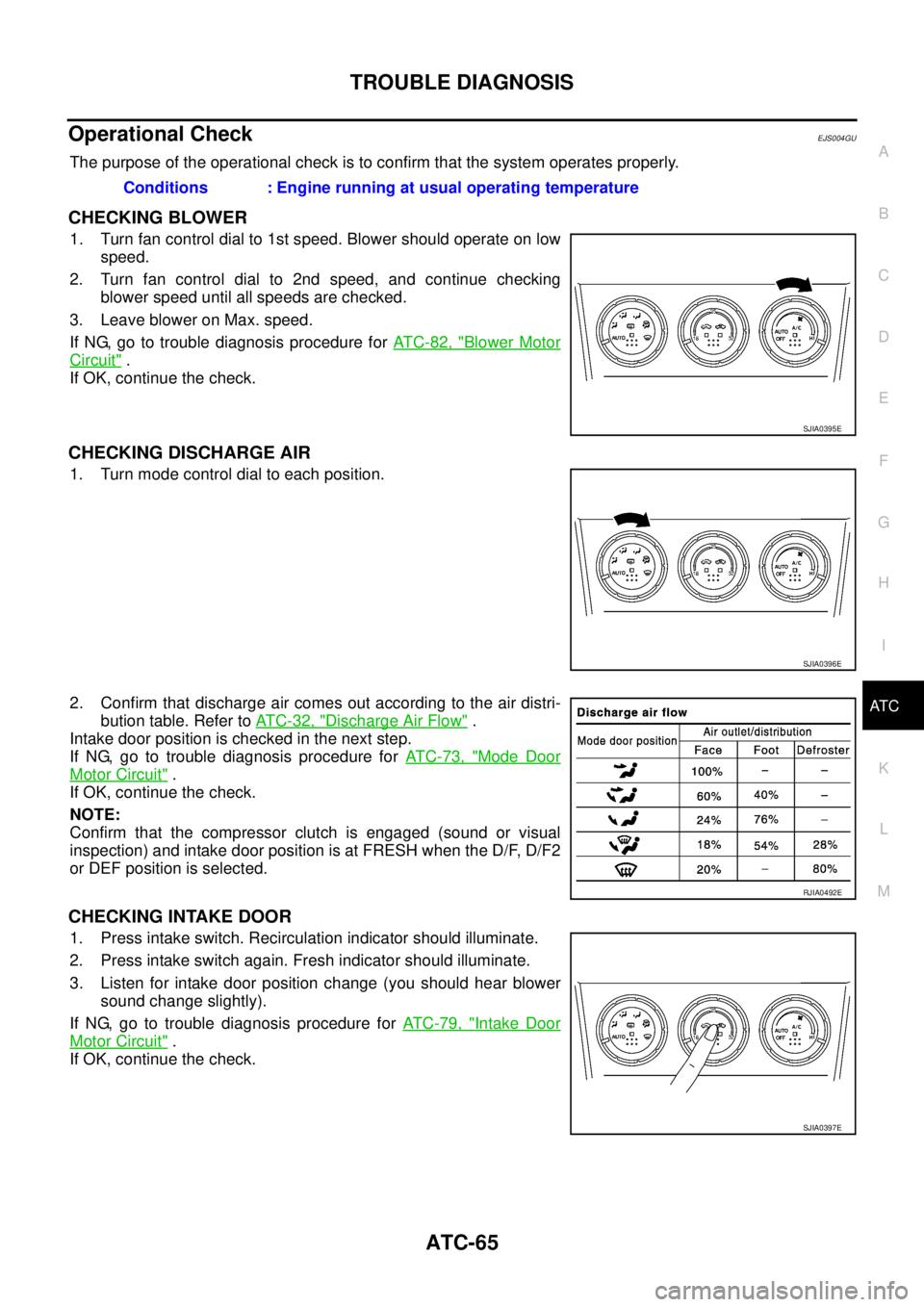
CHECKING DISCHARGE AIR
1. Turn mode control dial to each position.
2. Confirm that discharge air comes out according to the air distri-
bution table. Refer to AT C - 3 2 , "
Discharge Air Flow" .
Intake door position is checked in the next step.
If NG, go to trouble diagnosis procedure for AT C - 7 3 , "
Mode Door
Motor Circuit" .
If OK, continue the check.
NOTE:
Confirm that the compressor clutch is engaged (sound or visual
inspection) and intake door position is at FRESH when the D/F, D/F2
or DEF position is selected.
CHECKING INTAKE DOOR
1. Press intake switch. Recirculation indicator should illuminate.
2. Press intake switch again. Fresh indicator should illuminate.
3. Listen for intake door position change (you should hear blower
sound change slightly).
If NG, go to trouble diagnosis procedure for AT C - 7 9 , "
Intake Door
Motor Circuit" .
If OK, continue the check.Conditions : Engine running at usual operating temperature
SJIA0395E
SJIA0396E
RJIA0492E
SJIA0397E
Page 3244 of 4555
ATC-66
TROUBLE DIAGNOSIS
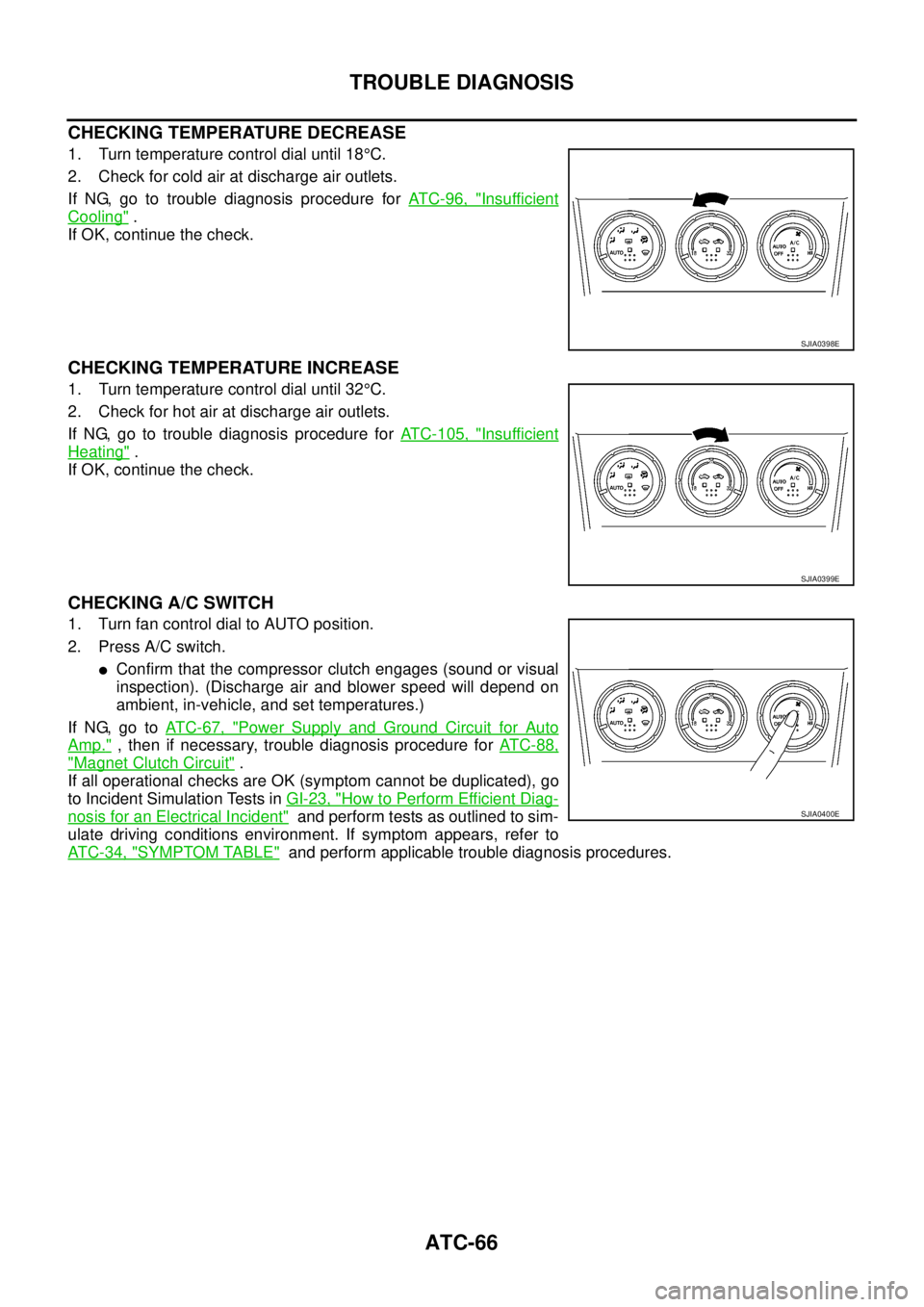
CHECKING TEMPERATURE DECREASE
1. Turn temperature control dial until 18°C.
2. Check for cold air at discharge air outlets.
If NG, go to trouble diagnosis procedure for AT C - 9 6 , "
Insufficient
Cooling" .
If OK, continue the check.
CHECKING TEMPERATURE INCREASE
1. Turn temperature control dial until 32°C.
2. Check for hot air at discharge air outlets.
If NG, go to trouble diagnosis procedure for ATC-105, "
Insufficient
Heating" .
If OK, continue the check.
CHECKING A/C SWITCH
1. Turn fan control dial to AUTO position.
2. Press A/C switch.
�Confirm that the compressor clutch engages (sound or visual
inspection). (Discharge air and blower speed will depend on
ambient, in-vehicle, and set temperatures.)
If NG, go to AT C - 6 7 , "
Power Supply and Ground Circuit for Auto
Amp." , then if necessary, trouble diagnosis procedure for AT C - 8 8 ,
"Magnet Clutch Circuit" .
If all operational checks are OK (symptom cannot be duplicated), go
to Incident Simulation Tests in GI-23, "
How to Perform Efficient Diag-
nosis for an Electrical Incident" and perform tests as outlined to sim-
ulate driving conditions environment. If symptom appears, refer to
AT C - 3 4 , "
SYMPTOM TABLE" and perform applicable trouble diagnosis procedures.
SJIA0398E
SJIA0399E
SJIA0400E
Page 3245 of 4555
TROUBLE DIAGNOSIS
ATC-67
C
D
E
F
G
H
I
K
L
MA
B
AT C
Power Supply and Ground Circuit for Auto Amp.EJS004GV
SYMPTOM: A/C system does not come on.
INSPECTION FLOW
COMPONENT DESCRIPTION
Auto Amp. (Automatic Amplifier)
The auto amp. has a built-in microcomputer which processes infor-
mation sent from various sensors needed for air conditioner opera-
tion. The air mix door motor, mode door motor, intake door motor,
blower motor and compressor are then controlled.
The auto amp. is unitized with control mechanisms. Signals from
various switches and Potentio Temperature Control (PTC) are
directly entered into auto amp.
Self-diagnostic functions are also built into auto amp. to provide
quick check of malfunctions in the auto air conditioner system.
*1AT C - 6 5 , "Operational Check".*2ATC-68, "DIAGNOSTIC PROCE-
DURE FOR A/C SYSTEM".
RJIA2826E
RJIA2824E
Page 3246 of 4555
ATC-68
TROUBLE DIAGNOSIS
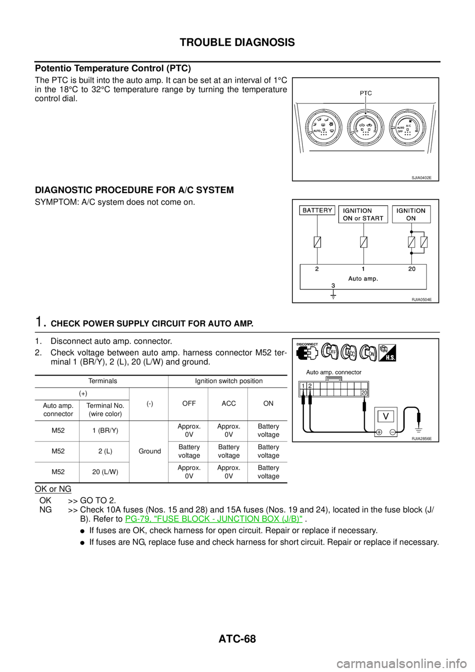
Potentio Temperature Control (PTC)
The PTC is built into the auto amp. It can be set at an interval of 1°C
in the 18°C to 32°C temperature range by turning the temperature
control dial.
DIAGNOSTIC PROCEDURE FOR A/C SYSTEM
SYMPTOM: A/C system does not come on.
1. CHECK POWER SUPPLY CIRCUIT FOR AUTO AMP.
1. Disconnect auto amp. connector.
2. Check voltage between auto amp. harness connector M52 ter-
minal 1 (BR/Y), 2 (L), 20 (L/W) and ground.
OK or NG
OK >> GO TO 2.
NG >> Check 10A fuses (Nos. 15 and 28) and 15A fuses (Nos. 19 and 24), located in the fuse block (J/
B). Refer to PG-79, "
FUSE BLOCK - JUNCTION BOX (J/B)" .
�If fuses are OK, check harness for open circuit. Repair or replace if necessary.
�If fuses are NG, replace fuse and check harness for short circuit. Repair or replace if necessary.
SJIA0402E
RJIA0504E
Terminals Ignition switch position
(+)
(-) OFF ACC ON
Auto amp.
connectorTe r m i n a l N o .
(wire color)
M52 1 (BR/Y)
GroundApprox.
0VApprox.
0VBattery
voltage
M52 2 (L)Battery
voltageBattery
voltageBattery
voltage
M52 20 (L/W)Approx.
0VApprox.
0VBattery
voltage
RJIA2856E
Page 3247 of 4555
TROUBLE DIAGNOSIS
ATC-69
C
D
E
F
G
H
I
K
L
MA
B
AT C
2. CHECK GROUND CIRCUIT FOR AUTO AMP.
1. Turn ignition switch OFF.
2. Check continuity between auto amp. harness connector M52
terminal 3 (B) and ground.
OK or NG
OK >> Replace auto amp.
NG >> Repair or replace harness.
LAN System CircuitEJS004L0
SYMPTOM: Mode door motor, intake door motor and/or air mix door motor(s) does not operate normally.
DIAGNOSTIC PROCEDURE FOR LAN CIRCUIT
1. CHECK POWER SUPPLY FOR AUTO AMP.
1. Turn ignition switch ON.
2. Check voltage between auto amp. harness connector M52 ter-
minal 5 (W) and ground.
OK or NG
OK >> GO TO 2.
NG >> Replace auto amp.3 – Ground : Continuity should exist.
RJIA2857E
RJIA0507E
5 – Ground : Battery voltage
RJIA2858E
Page 3248 of 4555
ATC-70
TROUBLE DIAGNOSIS
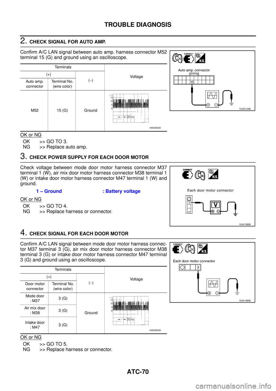
2. CHECK SIGNAL FOR AUTO AMP.
Confirm A/C LAN signal between auto amp. harness connector M52
terminal 15 (G) and ground using an oscilloscope.
OK or NG
OK >> GO TO 3.
NG >> Replace auto amp.
3. CHECK POWER SUPPLY FOR EACH DOOR MOTOR
Check voltage between mode door motor harness connector M37
terminal 1 (W), air mix door motor harness connector M38 terminal 1
(W) or intake door motor harness connector M47 terminal 1 (W) and
ground.
OK or NG
OK >> GO TO 4.
NG >> Replace harness or connector.
4. CHECK SIGNAL FOR EACH DOOR MOTOR
Confirm A/C LAN signal between mode door motor harness connec-
tor M37 terminal 3 (G), air mix door motor harness connector M38
terminal 3 (G) or intake door motor harness connector M47 terminal
3 (G) and ground using an oscilloscope.
OK or NG
OK >> GO TO 5.
NG >> Replace harness or connector.
Terminals
Voltag e (+)
(−)
Auto amp.
connectorTerminal No.
(wire color)
M52 15 (G) Ground
RJIA3128E
HAK0652D
1 – Ground : Battery voltage
RJIA1988E
Terminals
Voltage (+)
(−)
Door motor
connectorTerminal No.
(wire color)
Mode door
: M373 (G)
Ground Air mix door
: M383 (G)
Intake door
: M473 (G)
RJIA1989E
HAK0652D
Page 3249 of 4555
TROUBLE DIAGNOSIS
ATC-71
C
D
E
F
G
H
I
K
L
MA
B
AT C
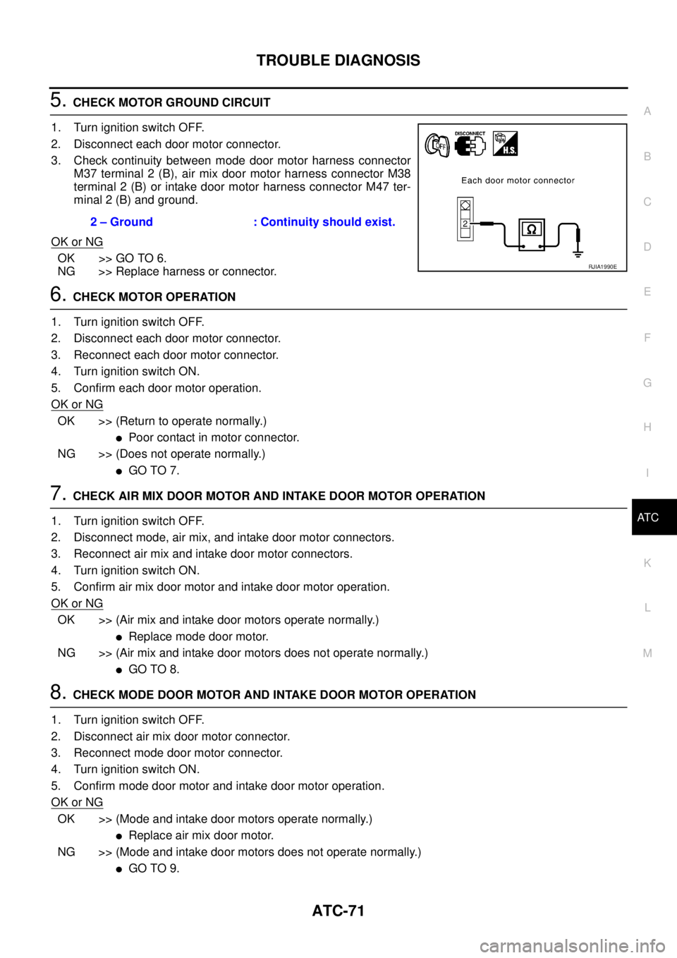
5. CHECK MOTOR GROUND CIRCUIT
1. Turn ignition switch OFF.
2. Disconnect each door motor connector.
3. Check continuity between mode door motor harness connector
M37 terminal 2 (B), air mix door motor harness connector M38
terminal 2 (B) or intake door motor harness connector M47 ter-
minal 2 (B) and ground.
OK or NG
OK >> GO TO 6.
NG >> Replace harness or connector.
6. CHECK MOTOR OPERATION
1. Turn ignition switch OFF.
2. Disconnect each door motor connector.
3. Reconnect each door motor connector.
4. Turn ignition switch ON.
5. Confirm each door motor operation.
OK or NG
OK >> (Return to operate normally.)
�Poor contact in motor connector.
NG >> (Does not operate normally.)
�GO TO 7.
7. CHECK AIR MIX DOOR MOTOR AND INTAKE DOOR MOTOR OPERATION
1. Turn ignition switch OFF.
2. Disconnect mode, air mix, and intake door motor connectors.
3. Reconnect air mix and intake door motor connectors.
4. Turn ignition switch ON.
5. Confirm air mix door motor and intake door motor operation.
OK or NG
OK >> (Air mix and intake door motors operate normally.)
�Replace mode door motor.
NG >> (Air mix and intake door motors does not operate normally.)
�GO TO 8.
8. CHECK MODE DOOR MOTOR AND INTAKE DOOR MOTOR OPERATION
1. Turn ignition switch OFF.
2. Disconnect air mix door motor connector.
3. Reconnect mode door motor connector.
4. Turn ignition switch ON.
5. Confirm mode door motor and intake door motor operation.
OK or NG
OK >> (Mode and intake door motors operate normally.)
�Replace air mix door motor.
NG >> (Mode and intake door motors does not operate normally.)
�GO TO 9. 2 – Ground : Continuity should exist.
RJIA1990E