Page 3266 of 4555
ATC-88
TROUBLE DIAGNOSIS
Magnet Clutch CircuitEJS004YO
SYMPTOM: Magnet clutch does not engage.
INSPECTION FLOW
*1AT C - 6 5 , "Operational Check".*2ATC-59, "FUNCTION CONFIRMA-
TION PROCEDURE", see No. 1.*3ATC-59, "
FUNCTION CONFIRMA-
TION PROCEDURE", see No. 5 to
7.
*4ATC-109, "
Ambient Sensor Circuit".*5ATC-117, "Intake Sensor Circuit".*6ATC-34, "SYMPTOM TABLE".
*7AT C - 5 9 , "
FUNCTION CONFIRMA-
TION PROCEDURE", see No. 9.*8ATC-89, "
DIAGNOSTIC PROCE-
DURE FOR MAGNET CLUTCH".*9ATC-102, "
TROUBLE DIAGNOSIS
FOR UNUSUAL PRESSURE".
RJIA3103E
Page 3268 of 4555
ATC-90
TROUBLE DIAGNOSIS
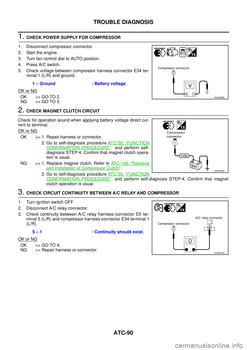
1. CHECK POWER SUPPLY FOR COMPRESSOR
1. Disconnect compressor connector.
2. Start the engine.
3. Turn fan control dial to AUTO position.
4. Press A/C switch.
5. Check voltage between compressor harness connector E34 ter-
minal 1 (L/R) and ground.
OK or NG
OK >> GO TO 2.
NG >> GO TO 3.
2. CHECK MAGNET CLUTCH CIRCUIT
Check for operation sound when applying battery voltage direct cur-
rent to terminal.
OK or NG
OK >> 1. Repair harness or connector.
2. Go to self-diagnosis procedure AT C - 5 9 , "
FUNCTION
CONFIRMATION PROCEDURE" and perform self-
diagnosis STEP-4. Confirm that magnet clutch opera-
tion is usual.
NG >> 1. Replace magnet clutch. Refer to ATC-146, "
Removal
and Installation of Compressor Clutch" .
2. Go to self-diagnosis procedure AT C - 5 9 , "
FUNCTION
CONFIRMATION PROCEDURE" and perform self-diagnosis STEP-4. Confirm that magnet
clutch operation is usual.
3. CHECK CIRCUIT CONTINUITY BETWEEN A/C RELAY AND COMPRESSOR
1. Turn ignition switch OFF.
2. Disconnect A/C relay connector.
3. Check continuity between A/C relay harness connector E5 ter-
minal 5 (L/R) and compressor harness connector E34 terminal 1
(L/R).
OK or NG
OK >> GO TO 4.
NG >> Repair harness or connector.1 – Ground : Battery voltage
RJIA2869E
RJIA2005E
5 – 1 : Continuity should exist.
RJIA2870E
Page 3269 of 4555
TROUBLE DIAGNOSIS
ATC-91
C
D
E
F
G
H
I
K
L
MA
B
AT C
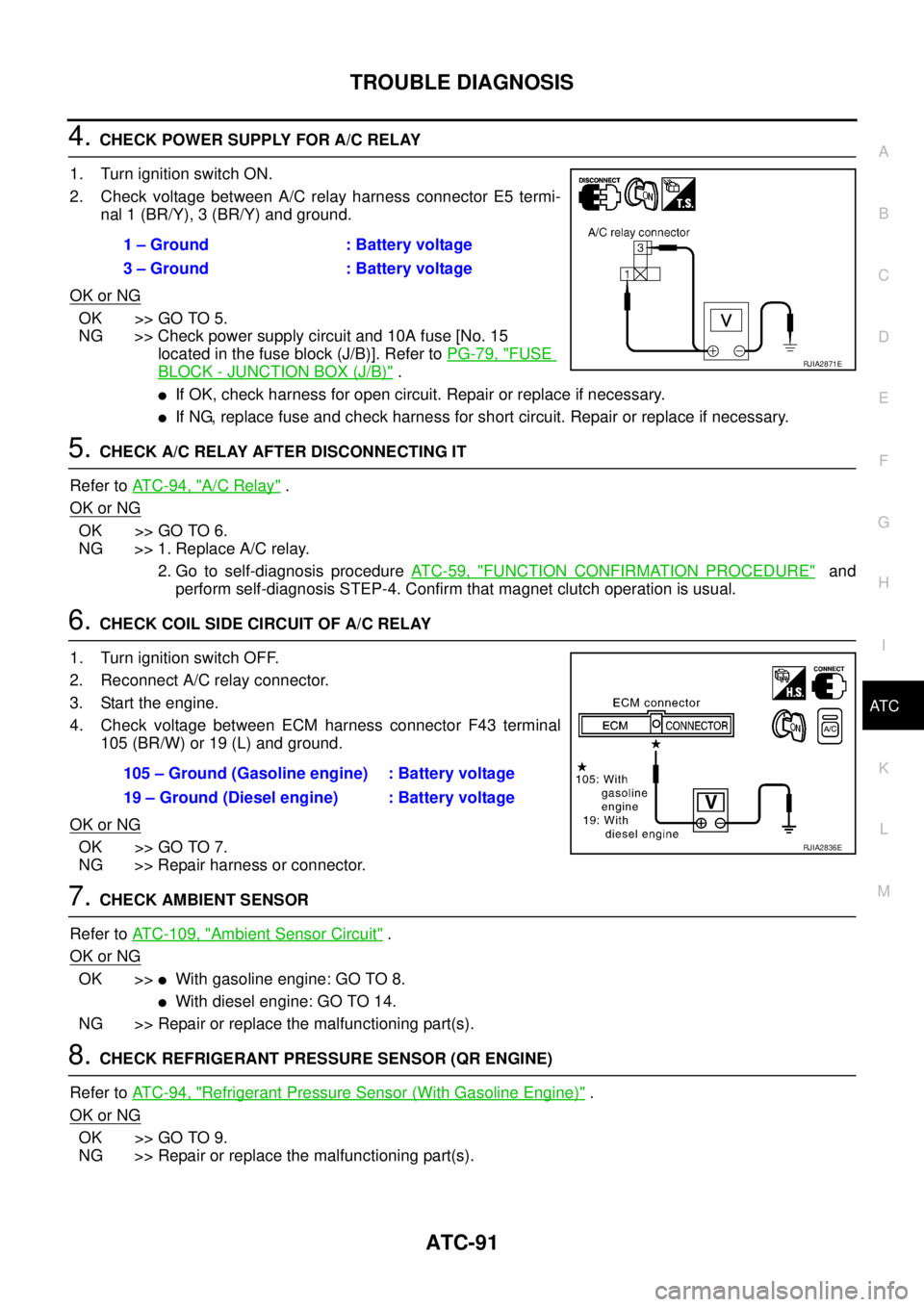
4. CHECK POWER SUPPLY FOR A/C RELAY
1. Turn ignition switch ON.
2. Check voltage between A/C relay harness connector E5 termi-
nal 1 (BR/Y), 3 (BR/Y) and ground.
OK or NG
OK >> GO TO 5.
NG >> Check power supply circuit and 10A fuse [No. 15
located in the fuse block (J/B)]. Refer to PG-79, "
FUSE
BLOCK - JUNCTION BOX (J/B)" .
�If OK, check harness for open circuit. Repair or replace if necessary.
�If NG, replace fuse and check harness for short circuit. Repair or replace if necessary.
5. CHECK A/C RELAY AFTER DISCONNECTING IT
Refer to AT C - 9 4 , "
A/C Relay" .
OK or NG
OK >> GO TO 6.
NG >> 1. Replace A/C relay.
2. Go to self-diagnosis procedure AT C - 5 9 , "
FUNCTION CONFIRMATION PROCEDURE" and
perform self-diagnosis STEP-4. Confirm that magnet clutch operation is usual.
6. CHECK COIL SIDE CIRCUIT OF A/C RELAY
1. Turn ignition switch OFF.
2. Reconnect A/C relay connector.
3. Start the engine.
4. Check voltage between ECM harness connector F43 terminal
105 (BR/W) or 19 (L) and ground.
OK or NG
OK >> GO TO 7.
NG >> Repair harness or connector.
7. CHECK AMBIENT SENSOR
Refer to ATC-109, "
Ambient Sensor Circuit" .
OK or NG
OK >>�With gasoline engine: GO TO 8.
�With diesel engine: GO TO 14.
NG >> Repair or replace the malfunctioning part(s).
8. CHECK REFRIGERANT PRESSURE SENSOR (QR ENGINE)
Refer to AT C - 9 4 , "
Refrigerant Pressure Sensor (With Gasoline Engine)" .
OK or NG
OK >> GO TO 9.
NG >> Repair or replace the malfunctioning part(s).1 – Ground : Battery voltage
3 – Ground : Battery voltage
RJIA2871E
105 – Ground (Gasoline engine) : Battery voltage
19 – Ground (Diesel engine) : Battery voltage
RJIA2836E
Page 3270 of 4555
ATC-92
TROUBLE DIAGNOSIS
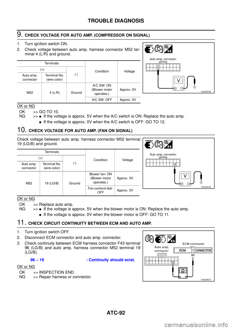
9. CHECK VOLTAGE FOR AUTO AMP. (COMPRESSOR ON SIGNAL)
1. Turn ignition switch ON.
2. Check voltage between auto amp. harness connector M52 ter-
minal 4 (L/R) and ground.
OK or NG
OK >> GO TO 10.
NG >>
�If the voltage is approx. 5V when the A/C switch is ON: Replace the auto amp.
�If the voltage is approx. 0V when the A/C switch is OFF: GO TO 12.
10. CHECK VOLTAGE FOR AUTO AMP. (FAN ON SIGNAL)
Check voltage between auto amp. harness connector M52 terminal
19 (LG/B) and ground.
OK or NG
OK >> Replace auto amp.
NG >>
�If the voltage is approx. 5V when the blower motor is ON: Replace the auto amp.
�If the voltage is approx. 0V when the blower motor is OFF: GO TO 11.
11 . CHECK CIRCUIT CONTINUITY BETWEEN ECM AND AUTO AMP.
1. Turn ignition switch OFF.
2. Disconnect ECM connector and auto amp. connector.
3. Check continuity between ECM harness connector F43 terminal
96 (LG/B) and auto amp. harness connector M52 terminal 19
(LG/B).
OK or NG
OK >> INSPECTION END
NG >> Repair harness or connector.
Te r m i n a l s
Condition Voltage (+)
(-)
Auto amp.
connectorTerminal No.
(wire color)
M52 4 (L/R) GroundA/C SW: ON
(Blower motor
operates.)Approx. 0V
A/C SW: OFF Approx. 5V
RJIA2873E
Terminals
Condition Voltage (+)
(-)
Auto amp.
connectorTerminal No.
(wire color)
M52 19 (LG/B) GroundBlower fan: ON
(Blower motor
operates.)Approx. 0V
Fan contorol dial:
OFFApprox. 5V
RJIA2874E
96 – 19 : Continuity should exist.
RJIA2837E
Page 3271 of 4555
TROUBLE DIAGNOSIS
ATC-93
C
D
E
F
G
H
I
K
L
MA
B
AT C
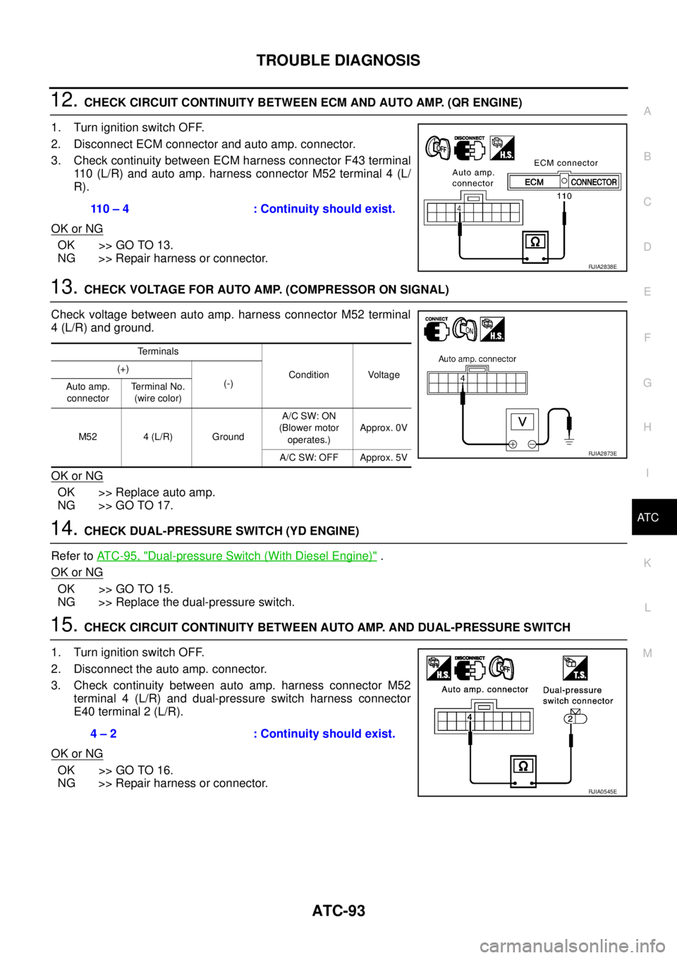
12. CHECK CIRCUIT CONTINUITY BETWEEN ECM AND AUTO AMP. (QR ENGINE)
1. Turn ignition switch OFF.
2. Disconnect ECM connector and auto amp. connector.
3. Check continuity between ECM harness connector F43 terminal
110 (L/R) and auto amp. harness connector M52 terminal 4 (L/
R).
OK or NG
OK >> GO TO 13.
NG >> Repair harness or connector.
13. CHECK VOLTAGE FOR AUTO AMP. (COMPRESSOR ON SIGNAL)
Check voltage between auto amp. harness connector M52 terminal
4 (L/R) and ground.
OK or NG
OK >> Replace auto amp.
NG >> GO TO 17.
14. CHECK DUAL-PRESSURE SWITCH (YD ENGINE)
Refer to AT C - 9 5 , "
Dual-pressure Switch (With Diesel Engine)" .
OK or NG
OK >> GO TO 15.
NG >> Replace the dual-pressure switch.
15. CHECK CIRCUIT CONTINUITY BETWEEN AUTO AMP. AND DUAL-PRESSURE SWITCH
1. Turn ignition switch OFF.
2. Disconnect the auto amp. connector.
3. Check continuity between auto amp. harness connector M52
terminal 4 (L/R) and dual-pressure switch harness connector
E40 terminal 2 (L/R).
OK or NG
OK >> GO TO 16.
NG >> Repair harness or connector.110 – 4 : Continuity should exist.
RJIA2838E
Terminals
Condition Voltage (+)
(-)
Auto amp.
connectorTerminal No.
(wire color)
M52 4 (L/R) GroundA/C SW: ON
(Blower motor
operates.)Approx. 0V
A/C SW: OFF Approx. 5V
RJIA2873E
4 – 2 : Continuity should exist.
RJIA0545E
Page 3272 of 4555
ATC-94
TROUBLE DIAGNOSIS
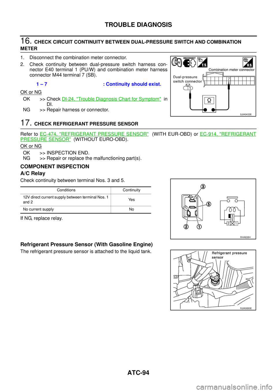
16. CHECK CIRCUIT CONTINUITY BETWEEN DUAL-PRESSURE SWITCH AND COMBINATION
METER
1. Disconnect the combination meter connector.
2. Check continuity between dual-pressure switch harness con-
nector E40 terminal 1 (PU/W) and combination meter harness
connector M44 terminal 7 (SB).
OK or NG
OK >> Check DI-24, "Trouble Diagnosis Chart for Symptom" in
DI.
NG >> Repair harness or connector.
17. CHECK REFRIGERANT PRESSURE SENSOR
Refer to EC-474, "
REFRIGERANT PRESSURE SENSOR" (WITH EUR-OBD) or EC-914, "REFRIGERANT
PRESSURE SENSOR" (WITHOUT EURO-OBD).
OK or NG
OK >> INSPECTION END.
NG >> Repair or replace the malfunctioning part(s).
COMPONENT INSPECTION
A/C Relay
Check continuity between terminal Nos. 3 and 5.
If NG, replace relay.
Refrigerant Pressure Sensor (With Gasoline Engine)
The refrigerant pressure sensor is attached to the liquid tank.1 – 7 : Continuity should exist.
SJIA0432E
Conditions Continuity
12V direct current supply between terminal Nos. 1
and 2Ye s
No current supply No
RHA638H
RJIA0690E
Page 3273 of 4555
TROUBLE DIAGNOSIS
ATC-95
C
D
E
F
G
H
I
K
L
MA
B
AT C
Dual-pressure Switch (With Diesel Engine)
Thermal Protector (With diesel engine)
Check continuity between compressor harness terminal and field
coil.
RJIA2954E
Compressor: ON
kPa (bar, kg/cm2 , psi)Compressor: OFF
kPa (bar, kg/cm2 , psi)
Low-pressure side 186 (1.86, 1.9, 27) 177 (1.77, 1.8, 26)
High-pressure side 1,569 (15.7, 16, 228) 2,746 (27.5, 28, 398)
RJIA0691E
RHA671H
Page 3274 of 4555
ATC-96
TROUBLE DIAGNOSIS
Insufficient CoolingEJS004H2
SYMPTOM: Insufficient cooling
INSPECTION FLOW
*1ATC-65, "Operational Check".*2ATC-59, "FUNCTION CONFIRMA-
TION PROCEDURE", see No. 1.*3AT C - 5 9 , "
FUNCTION CONFIRMA-
TION PROCEDURE", see No. 5 to 7.
*4 QR engine; EM-13, "
Checking Drive
Belts" or YD engine; EM-140,
"Checking Drive Belts" .*5ATC-76, "
Air Mix Door Motor Circuit".*6ATC-100, "Test Reading (QR
Engine)" or ATC-101, "Test Reading
(YD Engine)" .
*7ATC-63, "
AUXILIARY MECHA-
NISM: TEMPERATURE SETTING
TRIMMER".*8ATC-59, "
FUNCTION CONFIRMA-
TION PROCEDURE", see No. 9.*9AT C - 6 9 , "
LAN System Circuit".
SJIA0408E