Page 3250 of 4555
ATC-72
TROUBLE DIAGNOSIS
9. CHECK MODE DOOR MOTOR AND AIR MIX DOOR MOTOR OPERATION
1. Turn ignition switch OFF.
2. Disconnect intake door motor connector.
3. Reconnect air mix door motor connector.
4. Turn ignition switch ON.
5. Confirm mode door motor and air mix door motor operation.
OK or NG
OK >> (Mode and air mix door motors operate normally.)
�Replace intake door motor.
NG >> (Mode and air mix door motors does not operate normally.)
�Replace auto amp.
Page 3251 of 4555
TROUBLE DIAGNOSIS
ATC-73
C
D
E
F
G
H
I
K
L
MA
B
AT C
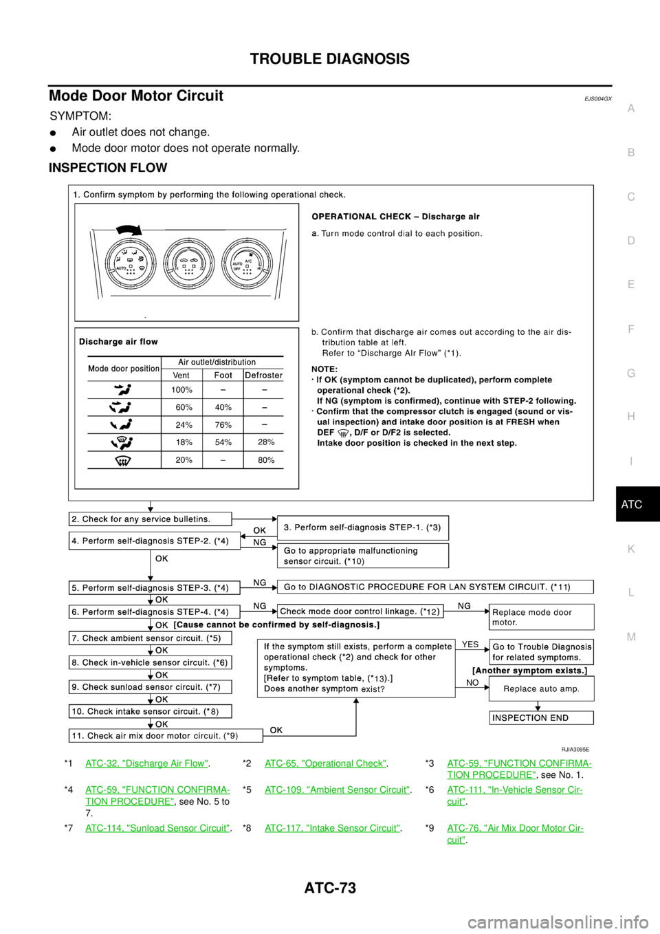
Mode Door Motor CircuitEJS004GX
SYMPTOM:
�Air outlet does not change.
�Mode door motor does not operate normally.
INSPECTION FLOW
*1ATC-32, "Discharge Air Flow".*2ATC-65, "Operational Check".*3ATC-59, "FUNCTION CONFIRMA-
TION PROCEDURE", see No. 1.
*4ATC-59, "
FUNCTION CONFIRMA-
TION PROCEDURE", see No. 5 to
7.*5ATC-109, "
Ambient Sensor Circuit".*6AT C - 111 , "In-Vehicle Sensor Cir-
cuit".
*7ATC-114, "
Sunload Sensor Circuit".*8ATC-117, "Intake Sensor Circuit".*9ATC-76, "Air Mix Door Motor Cir-
cuit".
RJIA3095E
Page 3254 of 4555
ATC-76
TROUBLE DIAGNOSIS
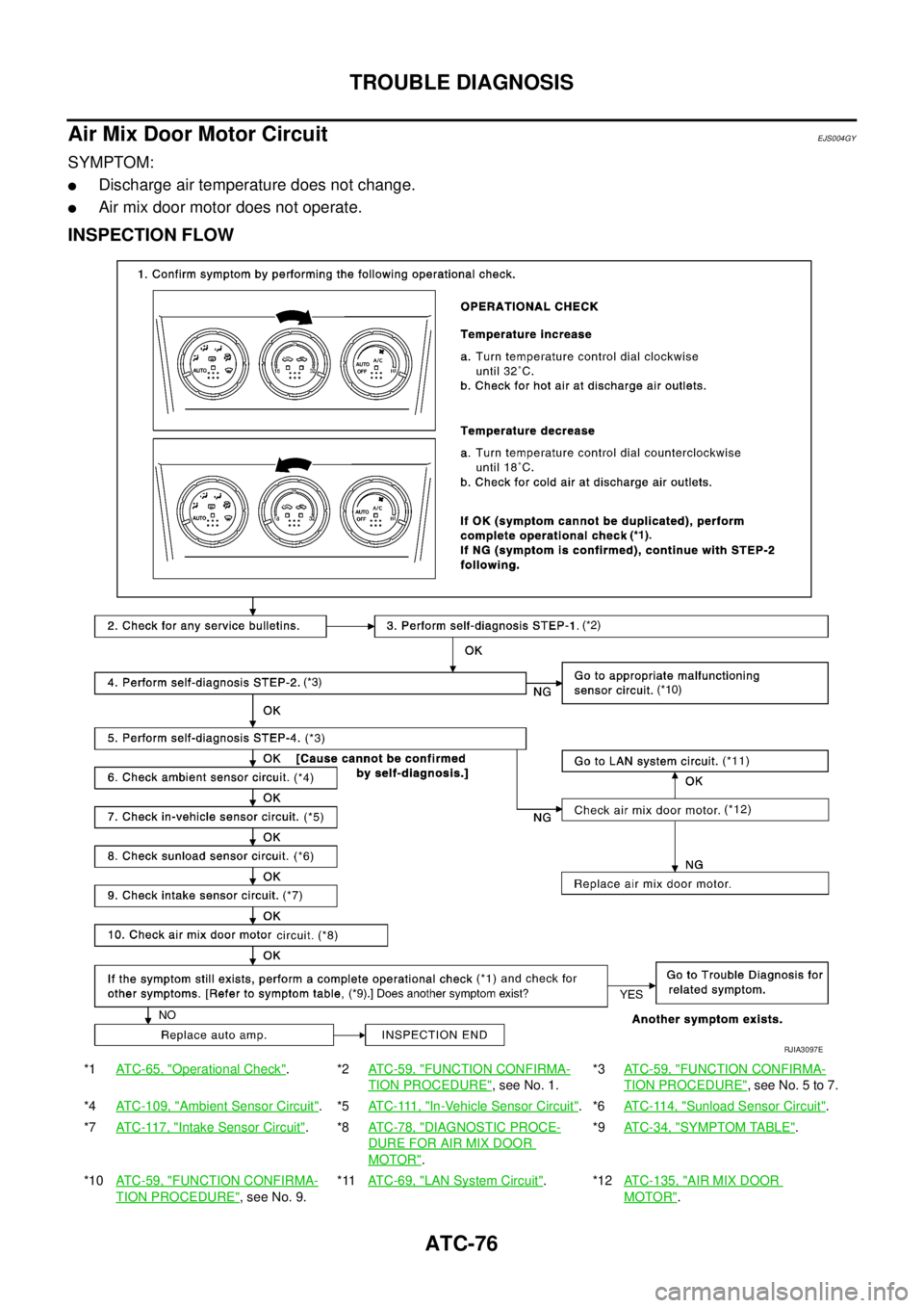
Air Mix Door Motor CircuitEJS004GY
SYMPTOM:
�Discharge air temperature does not change.
�Air mix door motor does not operate.
INSPECTION FLOW
*1AT C - 6 5 , "Operational Check".*2AT C - 5 9 , "FUNCTION CONFIRMA-
TION PROCEDURE", see No. 1.*3ATC-59, "
FUNCTION CONFIRMA-
TION PROCEDURE", see No. 5 to 7.
*4ATC-109, "
Ambient Sensor Circuit".*5AT C - 111 , "In-Vehicle Sensor Circuit".*6ATC-114, "Sunload Sensor Circuit".
*7AT C - 11 7 , "
Intake Sensor Circuit".*8AT C - 7 8 , "DIAGNOSTIC PROCE-
DURE FOR AIR MIX DOOR
MOTOR".*9ATC-34, "
SYMPTOM TABLE".
*10AT C - 5 9 , "
FUNCTION CONFIRMA-
TION PROCEDURE", see No. 9.*11AT C - 6 9 , "
LAN System Circuit".*12ATC-135, "AIR MIX DOOR
MOTOR".
RJIA3097E
Page 3257 of 4555
TROUBLE DIAGNOSIS
ATC-79
C
D
E
F
G
H
I
K
L
MA
B
AT C
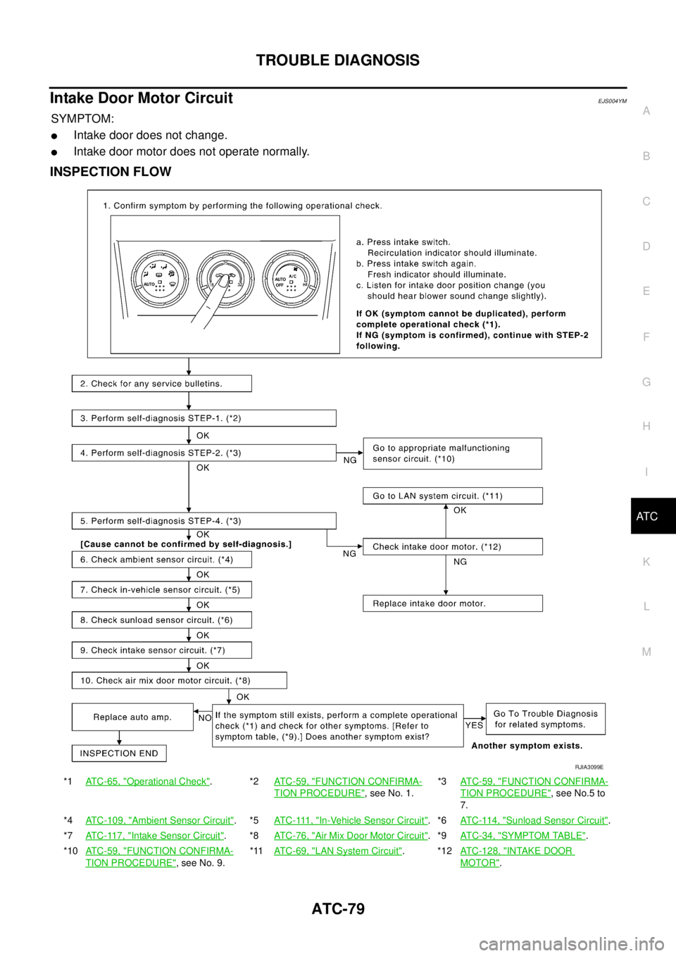
Intake Door Motor CircuitEJS004YM
SYMPTOM:
�Intake door does not change.
�Intake door motor does not operate normally.
INSPECTION FLOW
*1ATC-65, "Operational Check".*2ATC-59, "FUNCTION CONFIRMA-
TION PROCEDURE", see No. 1.*3AT C - 5 9 , "
FUNCTION CONFIRMA-
TION PROCEDURE", see No.5 to
7.
*4ATC-109, "
Ambient Sensor Circuit".*5AT C - 111 , "In-Vehicle Sensor Circuit".*6AT C - 11 4 , "Sunload Sensor Circuit".
*7ATC-117, "
Intake Sensor Circuit".*8ATC-76, "Air Mix Door Motor Circuit".*9AT C - 3 4 , "SYMPTOM TABLE".
*10ATC-59, "
FUNCTION CONFIRMA-
TION PROCEDURE", see No. 9.*11ATC-69, "
LAN System Circuit".*12ATC-128, "INTAKE DOOR
MOTOR".
RJIA3099E
Page 3260 of 4555
ATC-82
TROUBLE DIAGNOSIS
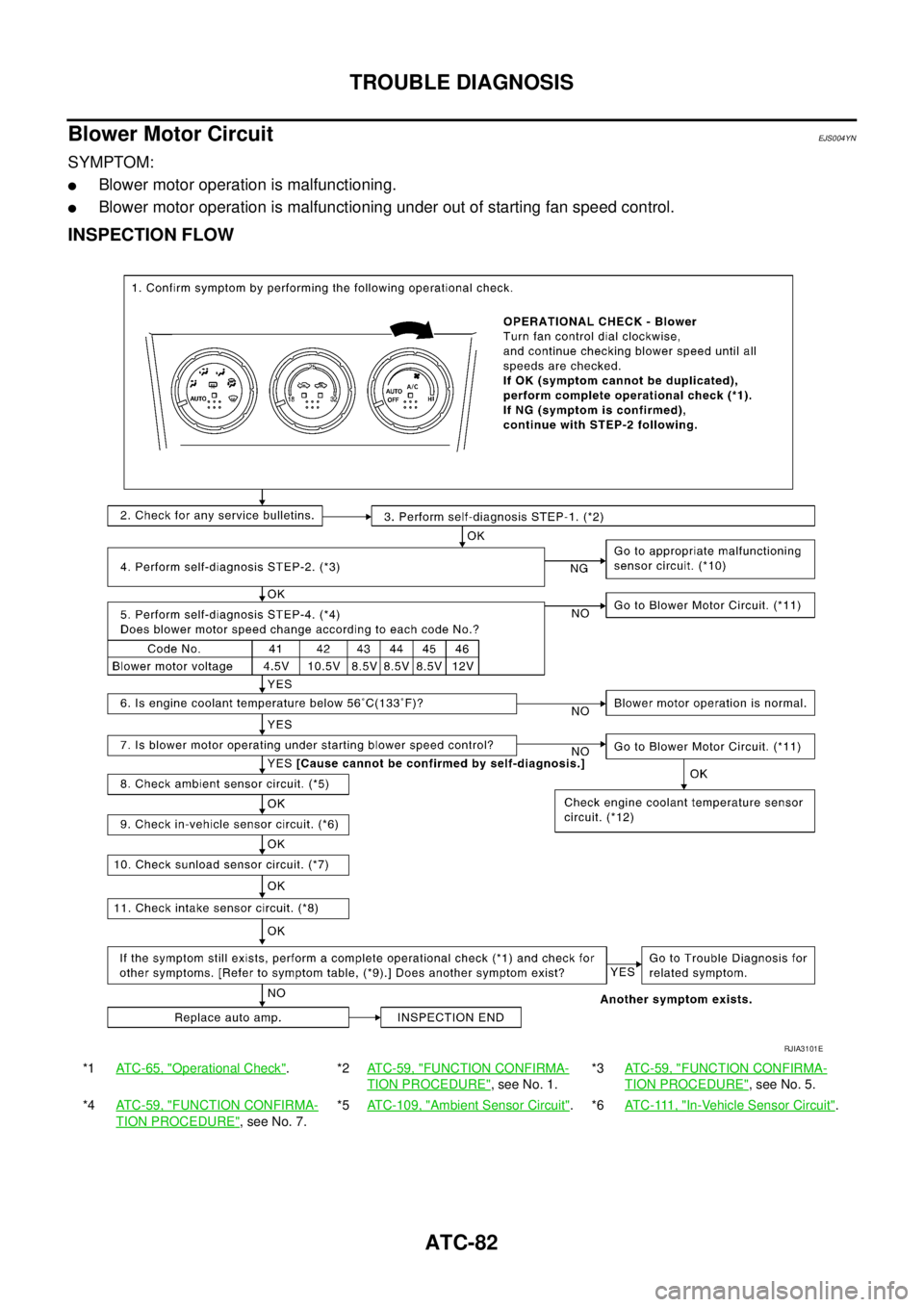
Blower Motor CircuitEJS004YN
SYMPTOM:
�Blower motor operation is malfunctioning.
�Blower motor operation is malfunctioning under out of starting fan speed control.
INSPECTION FLOW
*1ATC-65, "Operational Check".*2ATC-59, "FUNCTION CONFIRMA-
TION PROCEDURE", see No. 1.*3ATC-59, "
FUNCTION CONFIRMA-
TION PROCEDURE", see No. 5.
*4ATC-59, "
FUNCTION CONFIRMA-
TION PROCEDURE", see No. 7.*5ATC-109, "
Ambient Sensor Circuit".*6AT C - 111 , "In-Vehicle Sensor Circuit".
RJIA3101E
Page 3263 of 4555

TROUBLE DIAGNOSIS
ATC-85
C
D
E
F
G
H
I
K
L
MA
B
AT C
1. CHECK POWER SUPPLY FOR BLOWER MOTOR
1. Disconnect blower motor connector.
2. Turn ignition switch ON.
3. Check voltage between blower motor harness connector M65
terminal 1 (L/W) and ground.
OK or NG
OK >> GO TO 2.
NG >> Check power supply circuit and 15A fuses [Nos. 19 and
24, located in the fuse block (J/B)]. Refer to PG-79,
"FUSE BLOCK - JUNCTION BOX (J/B)" .
�If OK, check harness for open circuit. Repair or replace if necessary.
�If NG, replace fuse and check harness for short circuit. Repair or replace if necessary.
2. CHECK FAN FEED BACK CIRCUIT
1. Reconnect blower motor connector.
2. Check voltage between auto amp. harness connector M52 ter-
minal 18 (R) and ground.
OK or NG
OK >> GO TO 3.
NG >> GO TO 9.
3. CHECK BLOWER MOTOR
Refer to AT C - 8 7 , "
Blower Motor" .
OK or NG
OK >> GO TO 4.
NG >> Replace blower motor.
4. CHECK POWER SUPPLY FOR FAN CONTROL AMP.
1. Turn ignition switch ON.
2. Check voltage between fan control amp. harness connector
M67 terminal 3 (R) and ground.
OK or NG
OK >> GO TO 5.
NG >> Repair harness or connector.1 – Ground : Battery voltage
RJIA2860E
18 – Ground : Battery voltage
RJIA2861E
Terminals
Condition Voltage (+)
(-)
Fan control
amp. connectorTerminal No.
(wire color)
M67 3 (R) Ground Fan speed: 1st Approx. 8V
RJIA2862E
Page 3264 of 4555

ATC-86
TROUBLE DIAGNOSIS
5. CHECK GROUND CIRCUIT FOR FAN CONTROL AMP.
1. Turn ignition switch OFF.
2. Disconnect fan control amp. connector.
3. Check continuity between fan control amp. harness connector
M67 terminal 1 (B) and ground.
OK or NG
OK >> GO TO 6.
NG >> Repair harness or connector.
6. CHECK FOR AUTO AMP. OUTPUT SIGNAL
1. Reconnect fan control amp. connector.
2. Turn ignition switch ON.
3. Check voltage between fan control amp. harness connector
M67 terminal 2 (L/Y) and ground.
OK or NG
OK >> GO TO 9.
NG >>
�If the voltage is less than 2.5V: GO TO 7.
�If the voltage is more than 9.0V: GO TO 8.
7. CHECK CIRCUIT CONTINUITY BETWEEN AUTO AMP. AND FAN CONTROL AMP.
1. Turn ignition switch OFF.
2. Disconnect auto amp. connector and fan control amp. connec-
tor.
3. Check continuity between auto amp. harness connector M52
terminal 17 (L/Y) and fan control amp. harness connector M67
terminal 2 (L/Y).
OK or NG
OK >> Replace fan control amp.
NG >> Repair harness or connector.1 – Ground : Continuity should exist.
RJIA2863E
Terminals
Condition Voltage (+)
(-) Fan control
amp. connec-
torTerminal No.
(wire color)
M67 2 (L/Y) GroundFan speed: 1st
- 24thApprox. 2.5 -
3.5V
Fan
speed:25thApprox. 9.0V
RJIA2864E
17 – 2 : Continuity should exist.
RJIA2865E
Page 3265 of 4555
TROUBLE DIAGNOSIS
ATC-87
C
D
E
F
G
H
I
K
L
MA
B
AT C
8. CHECK FAN CONTROL AMP.
1. Turn ignition switch OFF.
2. Disconnect fan control amp. connector.
3. Check continuity between fan control amp. connector M67 ter-
minal 2 and 1.
OK or NG
OK >> GO TO 9.
NG >> Replace fan control amp.
9. CHECK CIRCUIT CONTINUITY BETWEEN AUTO AMP. AND FAN CONTROL AMP.
1. Disconnect auto amp. connector.
2. Check continuity between auto amp. harness connector M52
terminal 18 (R) and fan control amp. harness connector M67 ter-
minal 3 (R).
OK or NG
OK >> Replace auto amp.
NG >> Repair harness or connector.
COMPONENT INSPECTION
Blower Motor
Confirm smooth rotation of blower motor.
�Ensure that there are no foreign particles inside intake unit.2 – 1 : Continuity should exist.
SJIA0476E
18 – 3 : Continuity should exist.
RJIA2867E
RJIA0532E