Page 3784 of 4555
GW-70
POWER WINDOW SYSTEM
Limit Switch Circuit CheckEIS008BJ
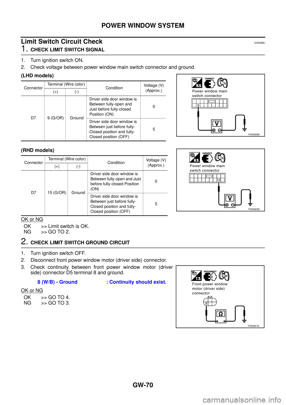
1. CHECK LIMIT SWITCH SIGNAL
1. Turn ignition switch ON.
2. Check voltage between power window main switch connector and ground.
(LHD models)
(RHD models)
OK or NG
OK >> Limit switch is OK.
NG >> GO TO 2.
2. CHECK LIMIT SWITCH GROUND CIRCUIT
1. Turn ignition switch OFF.
2. Disconnect front power window motor (driver side) connector.
3. Check continuity between front power window motor (driver
side) connector D5 terminal 8 and ground.
OK or NG
OK >> GO TO 4.
NG >> GO TO 3.
Connector Terminal (Wire color)
ConditionVoltage (V)
(Approx.)
(+) (-)
D7 9 (G/OR) GroundDriver side door window is
Between fully-open and
Just before fully-closed
Position (ON)0
Driver side door window is
Between just before fully-
Closed position and fully-
Closed position (OFF)5
Connector Terminal (Wire color)
ConditionVoltage (V)
(Approx.)
(+) (-)
D7 15 (G/OR) GroundDriver side door window is
Between fully-open and Just
before fully-closed Position
(ON)0
Driver side door window is
Between just before fully-
Closed position and fully-
Closed position (OFF)5
PIIA9599E
PIIA9600E
8 (W/B) - Ground : Continuity should exist.
PIIA9601E
Page 3785 of 4555
POWER WINDOW SYSTEM
GW-71
C
D
E
F
G
H
J
K
L
MA
B
GW
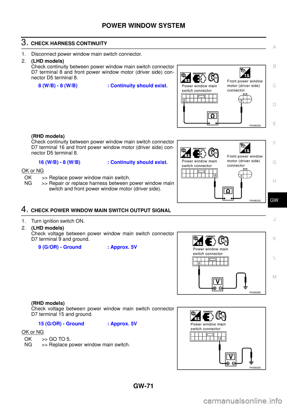
3. CHECK HARNESS CONTINUITY
1. Disconnect power window main switch connector.
2.(LHD models)
Check continuity between power window main switch connector
D7 terminal 8 and front power window motor (driver side) con-
nector D5 terminal 8.
(RHD models)
Check continuity between power window main switch connector
D7 terminal 16 and front power window motor (driver side) con-
nector D5 terminal 8.
OK or NG
OK >> Replace power window main switch.
NG >> Repair or replace harness between power window main
switch and front power window motor (driver side).
4. CHECK POWER WINDOW MAIN SWITCH OUTPUT SIGNAL
1. Turn ignition switch ON.
2.(LHD models)
Check voltage between power window main switch connector
D7 terminal 9 and ground.
(RHD models)
Check voltage between power window main switch connector
D7 terminal 15 and ground.
OK or NG
OK >> GO TO 5.
NG >> Replace power window main switch.8 (W/B) - 8 (W/B) : Continuity should exist.
PIIA9602E
16 (W/B) - 8 (W/B) : Continuity should exist.
PIIA9603E
9 (G/OR) - Ground : Approx. 5V
PIIA9599E
15 (G/OR) - Ground : Approx. 5V
PIIA9600E
Page 3786 of 4555
GW-72
POWER WINDOW SYSTEM
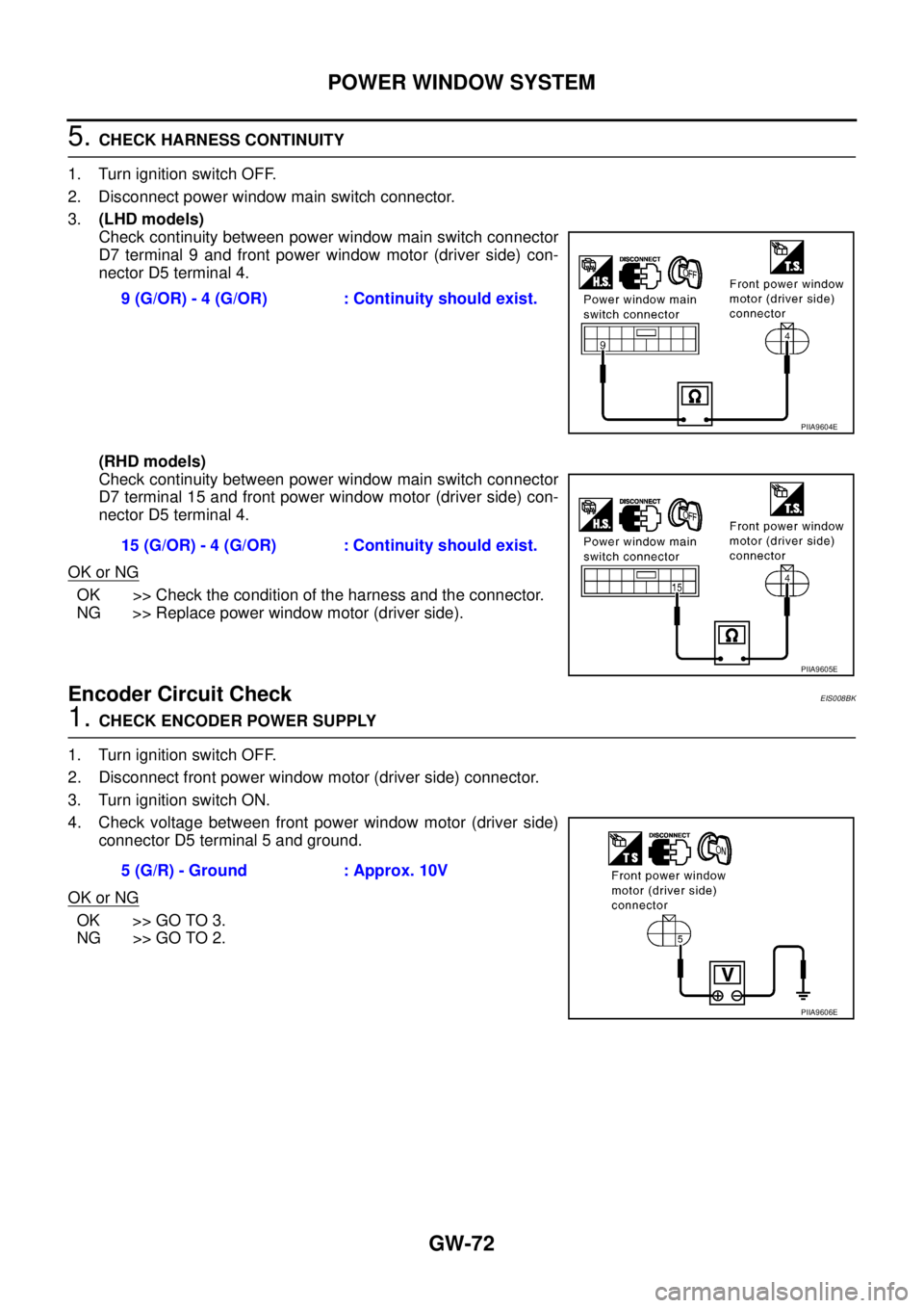
5. CHECK HARNESS CONTINUITY
1. Turn ignition switch OFF.
2. Disconnect power window main switch connector.
3.(LHD models)
Check continuity between power window main switch connector
D7 terminal 9 and front power window motor (driver side) con-
nector D5 terminal 4.
(RHD models)
Check continuity between power window main switch connector
D7 terminal 15 and front power window motor (driver side) con-
nector D5 terminal 4.
OK or NG
OK >> Check the condition of the harness and the connector.
NG >> Replace power window motor (driver side).
Encoder Circuit CheckEIS008BK
1. CHECK ENCODER POWER SUPPLY
1. Turn ignition switch OFF.
2. Disconnect front power window motor (driver side) connector.
3. Turn ignition switch ON.
4. Check voltage between front power window motor (driver side)
connector D5 terminal 5 and ground.
OK or NG
OK >> GO TO 3.
NG >> GO TO 2.9 (G/OR) - 4 (G/OR) : Continuity should exist.
PIIA9604E
15 (G/OR) - 4 (G/OR) : Continuity should exist.
PIIA9605E
5 (G/R) - Ground : Approx. 10V
PIIA9606E
Page 3787 of 4555
POWER WINDOW SYSTEM
GW-73
C
D
E
F
G
H
J
K
L
MA
B
GW
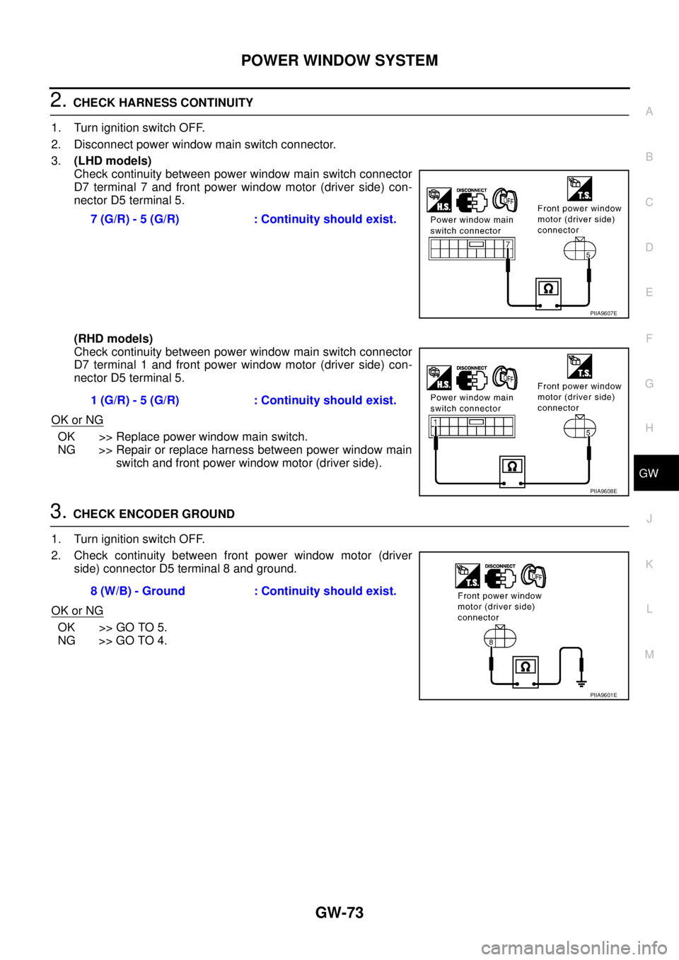
2. CHECK HARNESS CONTINUITY
1. Turn ignition switch OFF.
2. Disconnect power window main switch connector.
3.(LHD models)
Check continuity between power window main switch connector
D7 terminal 7 and front power window motor (driver side) con-
nector D5 terminal 5.
(RHD models)
Check continuity between power window main switch connector
D7 terminal 1 and front power window motor (driver side) con-
nector D5 terminal 5.
OK or NG
OK >> Replace power window main switch.
NG >> Repair or replace harness between power window main
switch and front power window motor (driver side).
3. CHECK ENCODER GROUND
1. Turn ignition switch OFF.
2. Check continuity between front power window motor (driver
side) connector D5 terminal 8 and ground.
OK or NG
OK >> GO TO 5.
NG >> GO TO 4.7 (G/R) - 5 (G/R) : Continuity should exist.
PIIA9607E
1 (G/R) - 5 (G/R) : Continuity should exist.
PIIA9608E
8 (W/B) - Ground : Continuity should exist.
PIIA9601E
Page 3789 of 4555
POWER WINDOW SYSTEM
GW-75
C
D
E
F
G
H
J
K
L
MA
B
GW
5. CHECK ENCODER SIGNAL
1. Connect front power window motor (driver side) connector.
2. Turn ignition switch ON.
3. Check the signal between power window main switch connector and ground with oscilloscope.
(LHD models)
(RHD models)
OK or NG
OK >> Replace power window main switch.
NG >> GO TO 6.
Connector Terminal
(Wire color)
ConditionSignal
(Reference value)
(+) (-)
D7 16 (G/Y) Ground opening
Connector Terminal
(Wire color)
ConditionSignal
(Reference value)
(+) (-)
D7 8 (G/Y) Ground opening
PIIA9609E
OCC3383D
PIIA9610E
OCC3383D
Page 3790 of 4555
GW-76
POWER WINDOW SYSTEM
6. CHECK ENCODER CIRCUIT
1. Turn ignition switch OFF.
2. Disconnect power window main switch and front power window motor (driver side) connector.
3.(LHD models)
Check continuity between power window main switch connector
D7 terminal 16 and front power window motor (driver side) con-
nector D5 terminal 6.
(RHD models)
Check continuity between power window main switch connector
D7 terminal 8 and front power window motor (driver side) con-
nector D5 terminal 6.
OK or NG
OK >> Replace front power window motor (driver side).
NG >> Repair or replace harness between power window main
switch and front power window motor (driver side). 16 (G/Y) - 6 (G/Y) : Continuity should exist.
PIIA9611E
8 (G/Y) - 6 (G/Y) : Continuity should exist.
PIIA9612E
Page 3792 of 4555
GW-78
POWER WINDOW SYSTEM
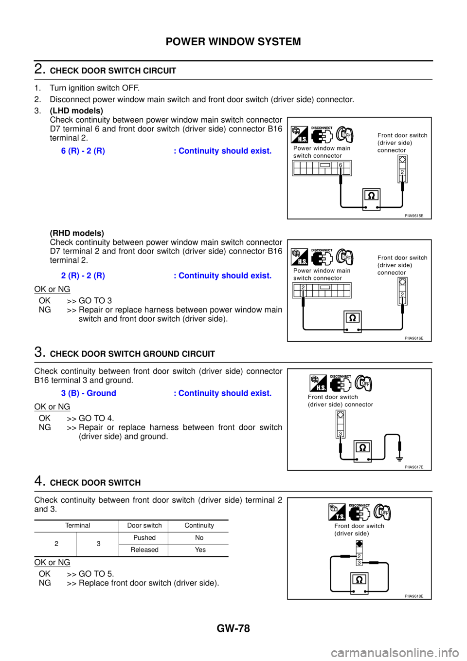
2. CHECK DOOR SWITCH CIRCUIT
1. Turn ignition switch OFF.
2. Disconnect power window main switch and front door switch (driver side) connector.
3.(LHD models)
Check continuity between power window main switch connector
D7 terminal 6 and front door switch (driver side) connector B16
terminal 2.
(RHD models)
Check continuity between power window main switch connector
D7 terminal 2 and front door switch (driver side) connector B16
terminal 2.
OK or NG
OK >> GO TO 3
NG >> Repair or replace harness between power window main
switch and front door switch (driver side).
3. CHECK DOOR SWITCH GROUND CIRCUIT
Check continuity between front door switch (driver side) connector
B16 terminal 3 and ground.
OK or NG
OK >> GO TO 4.
NG >> Repair or replace harness between front door switch
(driver side) and ground.
4. CHECK DOOR SWITCH
Check continuity between front door switch (driver side) terminal 2
and 3.
OK or NG
OK >> GO TO 5.
NG >> Replace front door switch (driver side).6 (R) - 2 (R) : Continuity should exist.
PIIA9615E
2 (R) - 2 (R) : Continuity should exist.
PIIA9616E
3 (B) - Ground : Continuity should exist.
PIIA9617E
Terminal Door switch Continuity
23Pushed No
Released Yes
PIIA9618E
Page 3936 of 4555
MTC-12
TROUBLE DIAGNOSIS
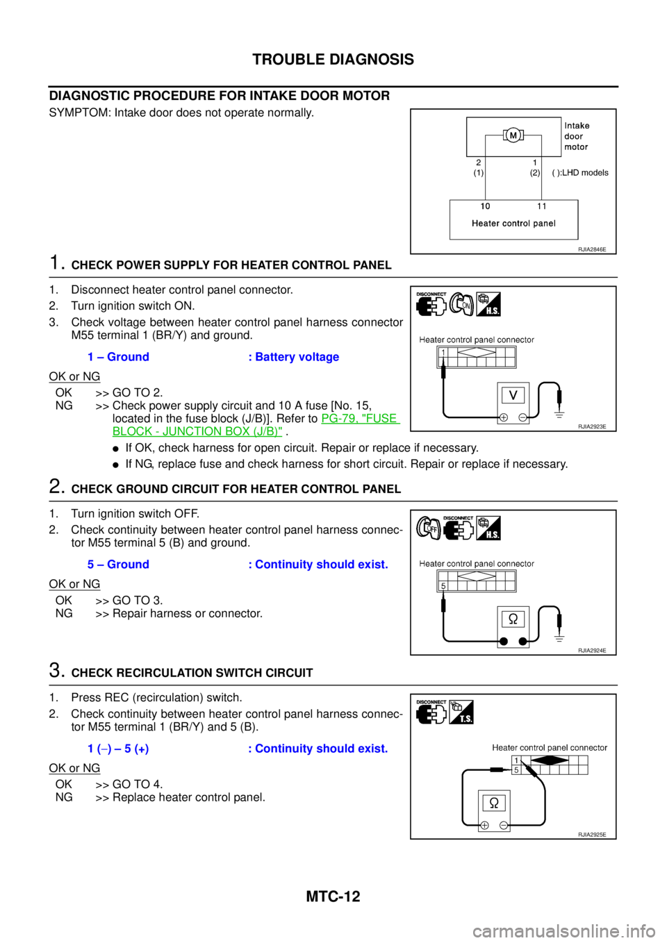
DIAGNOSTIC PROCEDURE FOR INTAKE DOOR MOTOR
SYMPTOM: Intake door does not operate normally.
1. CHECK POWER SUPPLY FOR HEATER CONTROL PANEL
1. Disconnect heater control panel connector.
2. Turn ignition switch ON.
3. Check voltage between heater control panel harness connector
M55 terminal 1 (BR/Y) and ground.
OK or NG
OK >> GO TO 2.
NG >> Check power supply circuit and 10 A fuse [No. 15,
located in the fuse block (J/B)]. Refer to PG-79, "
FUSE
BLOCK - JUNCTION BOX (J/B)" .
�If OK, check harness for open circuit. Repair or replace if necessary.
�If NG, replace fuse and check harness for short circuit. Repair or replace if necessary.
2. CHECK GROUND CIRCUIT FOR HEATER CONTROL PANEL
1. Turn ignition switch OFF.
2. Check continuity between heater control panel harness connec-
tor M55 terminal 5 (B) and ground.
OK or NG
OK >> GO TO 3.
NG >> Repair harness or connector.
3. CHECK RECIRCULATION SWITCH CIRCUIT
1. Press REC (recirculation) switch.
2. Check continuity between heater control panel harness connec-
tor M55 terminal 1 (BR/Y) and 5 (B).
OK or NG
OK >> GO TO 4.
NG >> Replace heater control panel.
RJIA2846E
1 – Ground : Battery voltage
RJIA2923E
5 – Ground : Continuity should exist.
RJIA2924E
1 (−) – 5 (+) : Continuity should exist.
RJIA2925E