Page 3502 of 4555
PS-40
HYDRAULIC LINE
QR25DE RH MODEL
1. Reservoir tank 2. Suction hose 3. High-pressure hose
4. Oil pump assembly 5. Steering gear assembly 6. Pressure sensor
7. O-ring 8. Copper washer 9. Eye-joint (assembled to high-pres-
sure side hose)
10. Eye-bolt
SGIA0947E
Page 3503 of 4555
HYDRAULIC LINE
PS-41
C
D
E
F
H
I
J
K
L
MA
B
PS
YD22DDTi LH MODEL
1. Reservoir tank 2. Suction hose 3. High-pressure hose
4. Oil pump assembly 5. Steering gear assembly 6. Pressure sensor
7. O-ring 8. Copper washer 9. Eye-joint (assembled to high-pres-
sure side hose)
10. Eye-bolt
SGIA0948E
Page 3504 of 4555
PS-42
HYDRAULIC LINE
YD22DDTi RH MODEL
1. Reservoir tank 2. Suction hose 3. High pressure hose
4. Oil pump assembly 5. Steering gear assembly 6. Pressure sensor
7. O-ring 8. Copper washer 9. Eye-joint (assembled to high-pres-
sure side hose
10. Eye-bolt
SGIA0949E
Page 3505 of 4555
HYDRAULIC LINE
PS-43
C
D
E
F
H
I
J
K
L
MA
B
PS
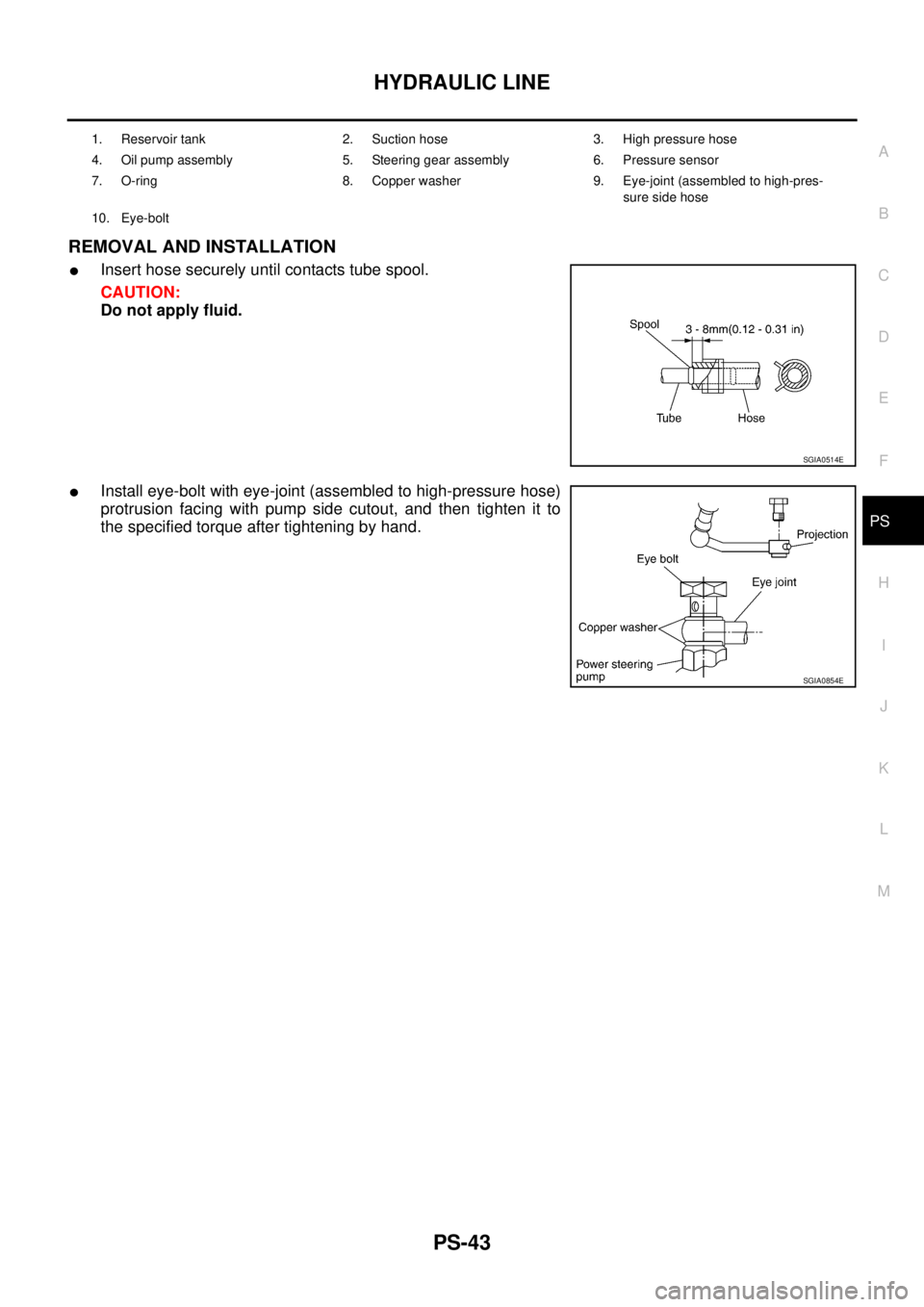
REMOVAL AND INSTALLATION
�Insert hose securely until contacts tube spool.
CAUTION:
Do not apply fluid.
�Install eye-bolt with eye-joint (assembled to high-pressure hose)
protrusion facing with pump side cutout, and then tighten it to
the specified torque after tightening by hand.
1. Reservoir tank 2. Suction hose 3. High pressure hose
4. Oil pump assembly 5. Steering gear assembly 6. Pressure sensor
7. O-ring 8. Copper washer 9. Eye-joint (assembled to high-pres-
sure side hose
10. Eye-bolt
SGIA0514E
SGIA0854E
Page 3507 of 4555
SERVICE DATA AND SPECIFICATIONS (SDS)
PS-45
C
D
E
F
H
I
J
K
L
MA
B
PS
Steering GearEGS0004T
Oil PumpEGS0004U
Steering FluidEGS0004V
Steering gear model PR24AD
Rack neutral position, dimension “L” (rack stroke) 66.5 mm (2.618 in)
SGIA0629J
Oil pump relief hydraulic pressure
Except YD22DDTi models
8,000 - 8,800 kPa (81.60 - 89.76 kg/cm
2 , 1,160 - 1,276 psi)
YD22DDTi models
8,500 - 9,300 kPa (98 - 104 kg/cm
2 , 1,390 - 1,480 psi)
Fluid capacity
Approx. 1.0 (1-1/8 US qt, 7/8 lmp qt)
Page 3996 of 4555

SERVICE DATA AND SPECIFICATIONS (SDS)PFP:00030
BatteryEKS0031Q
StarterEKS0031R
AlternatorEKS0031S
Applied modelQR20, QR25 engine
YD22 engine
Except
for N")
SC-36
SERVICE DATA AND SPECIFICATIONS (SDS)
SERVICE DATA AND SPECIFICATIONS (SDS)PFP:00030
BatteryEKS0031Q
StarterEKS0031R
AlternatorEKS0031S
Applied modelQR20, QR25 engine
YD22 engine
Except
for Northern EuropeFor Northern
Europe
Type 55D23L 80D23L 110D26L
Capacity [V - AH] 12-48 12-52 12-64
Applied modelQR20, QR25 engine
YD22 engine
A/T M/T
Ty p eS114-844 M0T87081 M8T71471
HITACHI make MITSUBISHI make
Reduction
System voltage [V] 12
No-loadTerminal voltage [V] 11.0
Current [A] Less than 90 Less than 90 Less than 145
Revolution [rpm] More than 2,700 More than 2,500 More than 3,300
Minimum diameter of commutator [mm (in)] 28.0 (1.102) 28.8 (1.134) 31.4 (1.236)
Minimum length of brush [mm (in)] 10.5 (0.413) 7.0 (0.276) 11.0 (0.433)
Brush spring tension [N (kg, lb)] 16.2 (1.65, 3.64)15.0 - 20.4
(1.5 - 2.1, 3.4 - 4.6)26.7 - 36.1
(2.7 - 3.7, 6.0 - 8.2)
Clearance between bearing metal and armature shaft [mm (in)] Less than 0.2 (0.008) —
Clearance “L” between pinion front edge and pinion
stopper[mm (in)] —0.5 - 2.0
(0.020 - 0.079)—
Movement “L” in height of pinion assembly [mm (in)]0.3 - 2.5
(0.012 - 0.098)—0.5 - 2.0
(0.020 - 0.079)
Applied model QR20, QR25 engine YD22 engine
Ty p eLR1110-713V A3TB0771
HITACHI make MITSUBISHI make
Nominal rating [V - A] 12-110 12-90
Ground polarityNegative
Minimum revolutions under no-load
(When 13.5 V is applied)[rpm] Less than 1,100 Less than 1,300
Hot output current (When 13.5 V is applied) [A/rpm](More than 35/1,300)
More than 70/1,800
More than 91/2,500
More than 110/5,000More than 29/1,300
More than 76/2,500
More than 88/5,000
Regulated output voltage [V] 14.1 - 14.7
Minimum length of brush [mm (in)] More than 6.0 (0.236) More than 5.0 (0.197)
Brush spring pressure [N (g, oz)]1.0 - 3.43
(102 - 350, 3.60 - 12.34)4.8 - 6.0
(490 - 610, 17.28 - 21.51)
Slip ring minimum diameter [mm (in)] More than 26.0 (1.024) More than 22.1 (0.870)
Rotor coil resistance at 20 °C (68 °F) [Ω] 2.16 - 2.46 2.1 - 2.5
Page 4014 of 4555

LT-18
HEADLAMP - XENON TYPE -
Aiming Adjustment of HeadlampEKS00N4Z
PREPARATION BEFORE ADJUSTING
For Details, Refer To The Regulations In Your Own Country.
Before performing aiming adjustment, check the following.
1. Keep all tires inflated to correct pressures.
2. Place vehicle on flat surface.
3. Set that there is no-load in vehicle other than the driver (or equivalent weight placed in driver's position).
Coolant, engine oil filled up to correct level and full fuel tank.
LOW BEAM
1. Turn headlamp low beam ON.
2. Use adjusting screws to perform aiming adjustment.
RH high beam does not operate, but
RH low beam operates.1. Bulb
2. Open in high beam RH circuit
3. Lighting switch
4. Headlamp RH ground circuit1. Check bulb.
2. Check the following.–Harness between headlamp RH and lighting switch for
open circuit.
3. Check lighting switch.
4. Check harness between headlamp RH and ground.
RH low beam does not operate, but
RH high beam operates.1. 20A fuse
2. HID relay RH
3. Open in RH low beam circuit
4. RH low beam ground circuit
5. Xenon bulb
6. HID control unit1. Check 20A fuse (No.51, located in fuse and fusible link
box). Verify battery positive voltage is present at terminal
5 of headlamp RH relay.
2. Check HID relay RH.
3. Check harness between HID relay RH terminal 3 and
headlamp RH terminal 2 for an open circuit.
4. Check harness between headlamp RH and ground.
5. Replace xenon bulb with other side bulb or new one. (If
headlamps illuminate correctly, replace bulb.)
6. Replace HID control unit with other side control unit or
new one. (If headlamps illuminate correctly, replace con-
trol unit.)
High beam indicator does not work.1. Bulb
2. Open in high beam circuit1. Check bulb in combination meter.
2. Check the harness circuit. Symptom Possible cause Repair order
PKIC0981E
Page 4015 of 4555

If the vehicle front body has been repaired and/or the headlamp assembly has bee")
HEADLAMP - XENON TYPE -
LT-19
C
D
E
F
G
H
I
J
L
MA
B
LT
ADJUSTMENT USING AN ADJUSTMENT SCREEN (LIGHT/DARK BORDERLINE)
If the vehicle front body has been repaired and/or the headlamp assembly has been replaced, check aiming.
Use the aiming chart shown in the figure.
�Basic illumination area for adjustment should be within the range shown on the aiming chart.
Adjust headlamp accordingly.
Aiming Adjustment of Driving LampEKS00N50
�Turn aiming adjusting screw to adjust.
�For positions of adjusting screws and direction to turn, refer to
the figures.
�When adjusting horizontal direction (right and left), turn two
adjusting screws to the same direction.
PREPARATION BEFORE ADJUSTING
For Details, Refer To The Regulations In Your Own Country.
Before performing aiming adjustment, check the following.
1. Keep all tires inflated to correct pressures.
2. Place vehicle on flat surface.
3. Set that there is no-load in vehicle other than the driver (or equivalent weight placed in driver's position).
Coolant, engine oil filled up to correct level and full fuel tank.
PKIC0481E
PKIA3394E


PS-45
C
D
E
F
H
I
J
K
L
MA
B
PS
Steering GearEGS0004T
Oil PumpEGS0004U
Steering FluidEGS0004V
Steering gear model PR24AD
Rack neutral position, dimension “L�")