Page 2643 of 4555
![NISSAN X-TRAIL 2005 Service Repair Manual BATT/FLUID TEMP SEN (A/T FLUID TEMP SENSOR CIRCUIT AND TCM POW-
ER SOURCE)
AT-379
[ALL]
D
E
F
G
H
I
J
K
L
MA
B
AT
5. CHECK FLUID TEMPERATURE SENSOR CIRCUIT
1. Turn ignition switch OFF.
2. Disconn](/manual-img/5/57403/w960_57403-2642.png "NISSAN X-TRAIL 2005 Service Repair Manual BATT/FLUID TEMP SEN (A/T FLUID TEMP SENSOR CIRCUIT AND TCM POW-
ER SOURCE)
AT-379
[ALL]
D
E
F
G
H
I
J
K
L
MA
B
AT
5. CHECK FLUID TEMPERATURE SENSOR CIRCUIT
1. Turn ignition switch OFF.
2. Disconn")
BATT/FLUID TEMP SEN (A/T FLUID TEMP SENSOR CIRCUIT AND TCM POW-
ER SOURCE)
AT-379
[ALL]
D
E
F
G
H
I
J
K
L
MA
B
AT
5. CHECK FLUID TEMPERATURE SENSOR CIRCUIT
1. Turn ignition switch OFF.
2. Disconnect the TCM connector.
3. Check resistance between terminals.
OK or NG
OK >> GO TO 9.
NG >> GO TO 6.
6. CHECK HARNESS BETWEEN TCM AND TERMINAL CORD ASSEMBLY HARNESS CONNECTOR
1. Turn ignition switch OFF.
2. Disconnect terminal cord assembly harness connector and TCM connector.
3. Check continuity between terminal cord assembly harness con-
nector and TCM connector.
4. If OK, check harness for short to ground and short to power.
5. If OK, check continuity between ground and transaxle assembly.
6. Reinstall any part removed.
OK or NG
OK >> GO TO 7.
NG >> Repair open circuit or short to ground or short to power in harness or connectors.
Name Connector
No. Terminal No.
(Wire color) Tempera-
ture °C (°F) Resistance
(KΩ) (Approx.)
A/T fluid
tempera-
ture sensor F47 47 (BR) - 42 (B) 20 (68) 2.5
80 (176) 0.3
SCIA2338E
Item Connector No.Terminal No.
(Wire color)Continuity
TCM F47 42 (B)
Ye s
Terminal cord assembly
harness connectorF23 7 (B)
Item Connector No.Terminal No.
(Wire color)Continuity
TCM F47 47 (BR)
Ye s
Terminal cord assembly
harness connectorF23 6 (BR)
SCIA2660E
Page 2644 of 4555
![NISSAN X-TRAIL 2005 Service Repair Manual AT-380
[ALL]
BATT/FLUID TEMP SEN (A/T FLUID TEMP SENSOR CIRCUIT AND TCM POW-
ER SOURCE)
7. CHECK A/T FLUID TEMPERATURE SENSOR WITH TERMINAL CORD ASSEMBLY
1. Turn ignition switch OFF.
2. Disconnect t](/manual-img/5/57403/w960_57403-2643.png "NISSAN X-TRAIL 2005 Service Repair Manual AT-380
[ALL]
BATT/FLUID TEMP SEN (A/T FLUID TEMP SENSOR CIRCUIT AND TCM POW-
ER SOURCE)
7. CHECK A/T FLUID TEMPERATURE SENSOR WITH TERMINAL CORD ASSEMBLY
1. Turn ignition switch OFF.
2. Disconnect t")
AT-380
[ALL]
BATT/FLUID TEMP SEN (A/T FLUID TEMP SENSOR CIRCUIT AND TCM POW-
ER SOURCE)
7. CHECK A/T FLUID TEMPERATURE SENSOR WITH TERMINAL CORD ASSEMBLY
1. Turn ignition switch OFF.
2. Disconnect terminal cord assembly connector in engine room.
3. Check resistance between terminal cord assembly F23 termi-
nals 6 (BR) and 7 (B) when A/T is cold.
4. Reinstall any part removed.
OK or NG
OK >> GO TO 8.
NG >> Repair or replace damaged parts.
8. DETECT MALFUNCTIONING ITEM
1. Remove oil pan. Refer to AT- 4 0 4 , "
Control Valve Assembly and Accumulators" .
2. Check the following items:
–A/T fluid temperature sensor
Check resistance between two terminals while changing temper-
ature as shown.
–Harness of terminal cord assembly for short or open
OK or NG
OK >> GO TO 9.
NG >> Repair or replace damaged parts.
9. CHECK DTC
Perform AT- 3 7 5 , "
DTC Confirmation Procedure" .
OK or NG
OK >>INSPECTION END
NG >> GO TO 10.
10. CHECK TCM
1. Check TCM input/output signal. Refer to AT- 9 4 , "
TCM Terminals and Reference Value" .
2. If NG, recheck TCM pin terminals for damage or loose connection with harness connector.
OK or NG
OK >>INSPECTION END
NG >> Repair or replace damaged parts.
Temperature °C (°F) Resistance
20 (68) Approx. 2.5 kΩ
80 (176) Approx. 0.3 kΩ
LCIA0095E
Temperature °C (°F) Resistance
20 (68) Approx. 2.5 kΩ
80 (176) Approx. 0.3 kΩ
SAT298F
Page 2645 of 4555
BATT/FLUID TEMP SEN (A/T FLUID TEMP SENSOR CIRCUIT AND TCM POW-
ER SOURCE)
AT-381
[ALL]
D
E
F
G
H
I
J
K
L
MA
B
AT
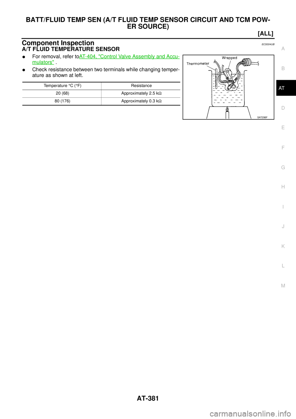
Component InspectionECS004UB
A/T FLUID TEMPERATURE SENSOR
�For removal, refer toAT- 4 0 4 , "Control Valve Assembly and Accu-
mulators" .
�Check resistance between two terminals while changing temper-
ature as shown at left.
Temperature °C (°F) Resistance
20 (68) Approximately 2.5 kΩ
80 (176) Approximately 0.3 kΩ
SAT298F
Page 2646 of 4555
![NISSAN X-TRAIL 2005 Service Repair Manual AT-382
[ALL]
ENGINE SPEED SIGNAL
ENGINE SPEED SIGNALPFP:24825
DescriptionECS004UC
The engine speed signal is sent from the ECM to the TCM.
CONSULT-II Reference ValueECS00CT2
Remarks: Specification d](/manual-img/5/57403/w960_57403-2645.png "NISSAN X-TRAIL 2005 Service Repair Manual AT-382
[ALL]
ENGINE SPEED SIGNAL
ENGINE SPEED SIGNALPFP:24825
DescriptionECS004UC
The engine speed signal is sent from the ECM to the TCM.
CONSULT-II Reference ValueECS00CT2
Remarks: Specification d")
AT-382
[ALL]
ENGINE SPEED SIGNAL
ENGINE SPEED SIGNALPFP:24825
DescriptionECS004UC
The engine speed signal is sent from the ECM to the TCM.
CONSULT-II Reference ValueECS00CT2
Remarks: Specification data are reference values.
On Board Diagnosis LogicECS00CT3
DTC Confirmation ProcedureECS00CT4
CAUTION:
�Always drive vehicle at a safe speed.
�If performing this “DTC Confirmation Procedure” again, always turn ignition switch OFF and wait
at least 10 seconds before continuing.
After the repair, perform the following procedure to confirm the malfunction is eliminated.
WITH CONSULT-II
1. Turn ignition switch ON and select “DATA MONITOR” mode for
“A/T” with CONSULT-II.
2. Start engine and maintain the following conditions for at least 10
consecutive seconds.
VHCL SPEED SE: 10 km/h (6 MPH) or more
THRTL POS SEN: More than 1.2V
SLCT LVR POSI: D position
3. If the check result is NG, go to AT- 3 8 4 , "
Diagnostic Procedure" .
WITHOUT CONSULT-II
1. Start engine.
2. Drive vehicle under the following conditions for more than 10 seconds.
Selector lever position: D position
Vehicle speed: higher than 10 km/h (6 MPH)
Throttle position: greater than 1.0/8 of the full throttle position
3. Perform self-diagnosis.
Refer to AT- 5 2 , "
Diagnostic Procedure Without CONSULT-II" .
4. If the check result is NG, go to AT- 3 8 4 , "
Diagnostic Procedure" .
Monitor item Condition Display value
ENGINE SPEED (rpm) Engine running Approximately matches the tachometer
reading.
Diagnostic trouble code Malfunction is detected when... Check item (Possible cause)
: ENGINE SPEED SIG
TCM does not receive the proper voltage
signal from ECM.
�Harness or connectors
(The sensor circuit is open or shorted.)
: 9th judgement flicker
SAT014K
SCIA5599E
Page 2676 of 4555
AT-412
[ALL]
ON-VEHICLE SERVICE
Revolution Sensor ReplacementECS0040G
COMPONENTS
1. Remove front tire LH from vehicle.
2. Remove LH splash guard.(Front fender side) Refer toEI-21, "
Removal and Installation" .
3. Disconnect revolution sensor harness connector.
4. Remove harness bracket from transaxle assembly.
5. Remove revolution sensor from transaxle assembly.
Installation
Note the following, and install in the reverse order of removal.
CAUTION:
�Do not reuse O-ring.
�Apply petroleum jelly to O-ring.
1. transaxle assembly 2. Revolution sensor 3. O-ring
SCIA4864E
SCIA2788E
Page 2677 of 4555
![NISSAN X-TRAIL 2005 Service Repair Manual REMOVAL AND INSTALLATION
AT-413
[ALL]
D
E
F
G
H
I
J
K
L
MA
B
AT
REMOVAL AND INSTALLATIONPFP:00000
RemovalECS004NC
COMPONENTS
CAUTION:
Before separating transaxle from engine, remove the crankshaft p](/manual-img/5/57403/w960_57403-2676.png "NISSAN X-TRAIL 2005 Service Repair Manual REMOVAL AND INSTALLATION
AT-413
[ALL]
D
E
F
G
H
I
J
K
L
MA
B
AT
REMOVAL AND INSTALLATIONPFP:00000
RemovalECS004NC
COMPONENTS
CAUTION:
Before separating transaxle from engine, remove the crankshaft p")
REMOVAL AND INSTALLATION
AT-413
[ALL]
D
E
F
G
H
I
J
K
L
MA
B
AT
REMOVAL AND INSTALLATIONPFP:00000
RemovalECS004NC
COMPONENTS
CAUTION:
Before separating transaxle from engine, remove the crankshaft position sensor (Euro-OBD) from
transaxle. Be careful not to damage sensor.
1. Remove battery and bracket, air cleaner and air duct.
2. Remove air breather hose.
3. Disconnect terminal cord assembly harness connector, PNP switch harness connector and revolution
sensor harness connector.
4. Remove crankshaft position sensor (Euro-OBD) from transaxle.
5. Disconnect control cable from transaxle.
6. Remove front exhaust tube. Refer to EX-2, "
Removal and Installation"
7. Disconnect A/T fluid cooler hoses.
8. Remove drive shafts. Refer to FAX-11, "
FRONT DRIVE SHAFT" , RAX-14, "REAR DRIVE SHAFT" .
9. Remove transfer assembly. Refer to TF-57, "
Removal and Installation" .
10. Remove starter motor from transaxle. Refer to SC-27, "
Removal and Installation" .
11. Support transaxle with a transmission jack.
1. Transfer assembly 2. A/T fluid level gauge 3. A/T fluid charging pipe
4. O-ring 5. Center member 6. Front engine mounting insulator
7. Grommet 8. Fluid cooler tube 9. Fluid cooler tube
10. Copper washer 11. Copper washer 12. Transaxle assembly
13. Stopper 14. LH engine mounting insulator
SCIA6893E
Page 2684 of 4555
AT-420
[ALL]
OVERHAUL
1. Side cover fitting bolt 2. Output shaft bearing 3. Output shaft
4. Seal ring 5. Needle bearing 6. Parking actuator support
7. LH differential side oil seal 8. O-ring 9. Revolution sensor
SCIA4862E
Page 2689 of 4555
![NISSAN X-TRAIL 2005 Service Repair Manual DISASSEMBLY
AT-425
[ALL]
D
E
F
G
H
I
J
K
L
MA
B
AT
4. Set manual shaft to position P.
5. Remove park/neutral position (PNP) switch.
6. Remove bracket from transaxle case.
7. Remove revolution sensor](/manual-img/5/57403/w960_57403-2688.png "NISSAN X-TRAIL 2005 Service Repair Manual DISASSEMBLY
AT-425
[ALL]
D
E
F
G
H
I
J
K
L
MA
B
AT
4. Set manual shaft to position P.
5. Remove park/neutral position (PNP) switch.
6. Remove bracket from transaxle case.
7. Remove revolution sensor")
DISASSEMBLY
AT-425
[ALL]
D
E
F
G
H
I
J
K
L
MA
B
AT
4. Set manual shaft to position P.
5. Remove park/neutral position (PNP) switch.
6. Remove bracket from transaxle case.
7. Remove revolution sensor from transaxle case.
8. Remove O-ring from revolution sensor.
9. Remove oil pan and oil pan gasket.
�Do not reuse oil pan bolts.
10. Check foreign materials in oil pan to help determine causes of
malfunction. If the fluid is very dark, smells burned, or contains
foreign particles, the frictional material (clutches, band) may
need replacement. A tacky film that will not wipe clean indicates
varnish build up. Varnish can cause valves, servo, and clutches
to stick and can inhibit pump pressure.
�If frictional material is detected, replace radiator after
repair of A/T. Refer to CO-12, "
RADIATOR" .
11. Remove magnets from oil pan.
12. Remove control valve assembly according to the following procedures.
a. Remove snap ring from terminal body.
b. Push terminal body into transaxle case and draw out terminal
cord assembly.
SCIA3154E
SCIA3476E
SCIA4866E
SCIA0801E
![NISSAN X-TRAIL 2005 Service Repair Manual AT-412
[ALL]
ON-VEHICLE SERVICE
Revolution Sensor ReplacementECS0040G
COMPONENTS
1. Remove front tire LH from vehicle.
2. Remove LH splash guard.(Front fender side) Refer toEI-21, "
Removal and Inst](/manual-img/5/57403/w960_57403-2675.png "NISSAN X-TRAIL 2005 Service Repair Manual AT-412
[ALL]
ON-VEHICLE SERVICE
Revolution Sensor ReplacementECS0040G
COMPONENTS
1. Remove front tire LH from vehicle.
2. Remove LH splash guard.(Front fender side) Refer toEI-21, \"
Removal and Inst")
![NISSAN X-TRAIL 2005 Service Repair Manual AT-420
[ALL]
OVERHAUL
1. Side cover fitting bolt 2. Output shaft bearing 3. Output shaft
4. Seal ring 5. Needle bearing 6. Parking actuator support
7. LH differential side oil seal 8. O-ring 9. Revo](/manual-img/5/57403/w960_57403-2683.png "NISSAN X-TRAIL 2005 Service Repair Manual AT-420
[ALL]
OVERHAUL
1. Side cover fitting bolt 2. Output shaft bearing 3. Output shaft
4. Seal ring 5. Needle bearing 6. Parking actuator support
7. LH differential side oil seal 8. O-ring 9. Revo")