Page 2856 of 4555

TF-52
TROUBLE DIAGNOSIS FOR SYMPTOMS
DIAGNOSTIC PROCEDURE
1. CHECK PARKING BRAKE SWITCH SIGNAL
With CONSULT-II
1. Turn ignition switch “ON”.
2. Select “DATA MONITOR” mode for “ALL MODE AWD/4WD” with CONSULT-II.
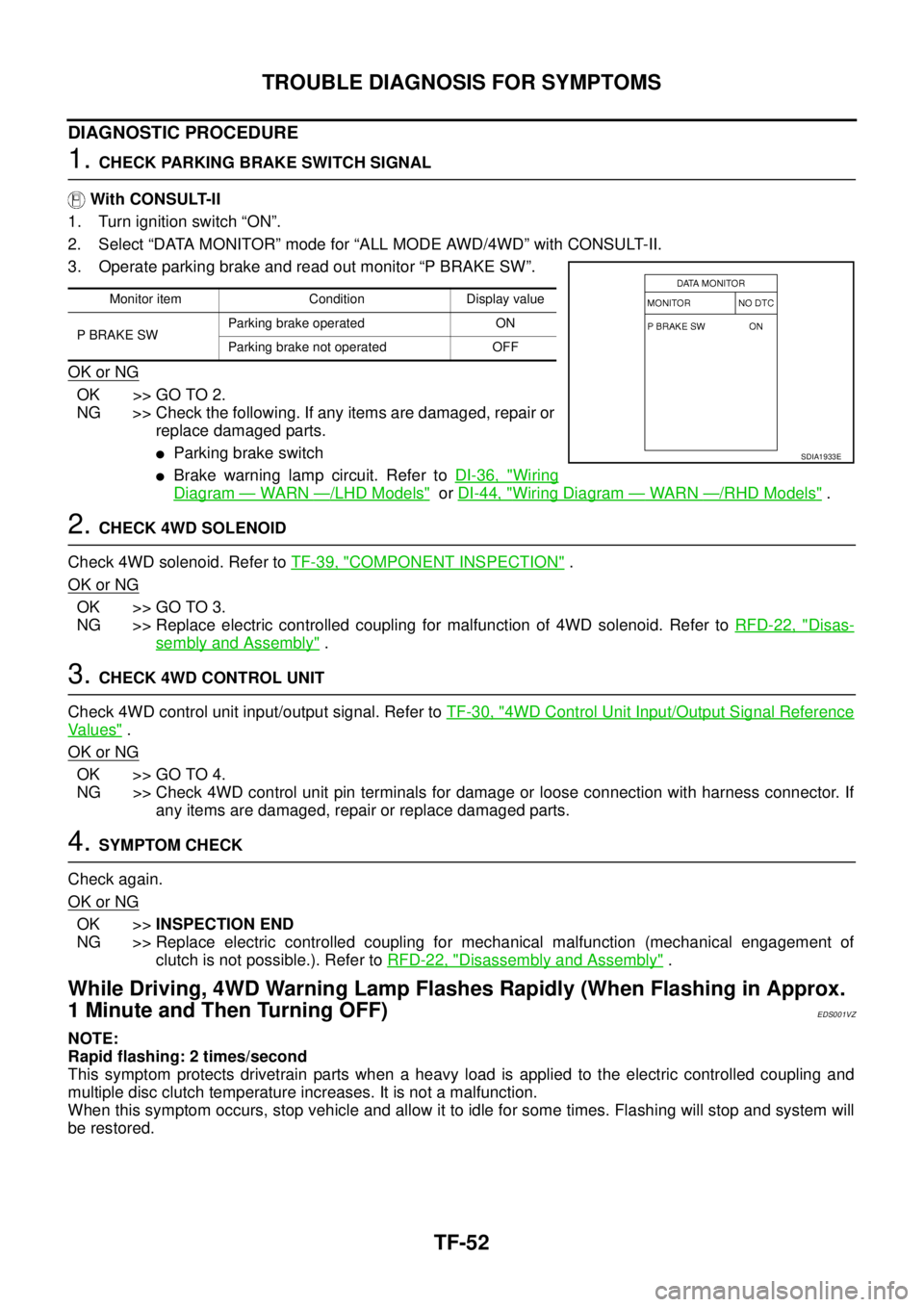
3. Operate parking brake and read out monitor “P BRAKE SW”.
OK or NG
OK >> GO TO 2.
NG >> Check the following. If any items are damaged, repair or
replace damaged parts.
�Parking brake switch
�Brake warning lamp circuit. Refer to DI-36, "Wiring
Diagram — WARN —/LHD Models" or DI-44, "Wiring Diagram — WARN —/RHD Models" .
2. CHECK 4WD SOLENOID
Check 4WD solenoid. Refer to TF-39, "
COMPONENT INSPECTION" .
OK or NG
OK >> GO TO 3.
NG >> Replace electric controlled coupling for malfunction of 4WD solenoid. Refer to RFD-22, "
Disas-
sembly and Assembly" .
3. CHECK 4WD CONTROL UNIT
Check 4WD control unit input/output signal. Refer to TF-30, "
4WD Control Unit Input/Output Signal Reference
Va l u e s" .
OK or NG
OK >> GO TO 4.
NG >> Check 4WD control unit pin terminals for damage or loose connection with harness connector. If
any items are damaged, repair or replace damaged parts.
4. SYMPTOM CHECK
Check again.
OK or NG
OK >>INSPECTION END
NG >> Replace electric controlled coupling for mechanical malfunction (mechanical engagement of
clutch is not possible.). Refer to RFD-22, "
Disassembly and Assembly" .
While Driving, 4WD Warning Lamp Flashes Rapidly (When Flashing in Approx.
1 Minute and Then Turning OFF)
EDS001VZ
NOTE:
Rapid flashing: 2 times/second
This symptom protects drivetrain parts when a heavy load is applied to the electric controlled coupling and
multiple disc clutch temperature increases. It is not a malfunction.
When this symptom occurs, stop vehicle and allow it to idle for some times. Flashing will stop and system will
be restored.
Monitor item Condition Display value
P BRAKE SWParking brake operated ON
Parking brake not operated OFF
SDIA1933E
Page 2857 of 4555

TROUBLE DIAGNOSIS FOR SYMPTOMS
TF-53
C
E
F
G
H
I
J
K
L
MA
B
TF
While Driving, 4WD Warning Lamp Flashes Slowly (When Continuing to Flash
until Turning Ignition Switch OFF)
EDS001W0
NOTE:
Slow flashing: 1 time/2 seconds
DIAGNOSTIC PROCEDURE
1. CHECK TIRE
Check the following.
�Tire pressure
�Wear condition
�Longitudinal tire size (There shall be no difference of tire size between front and rear tires.)
OK or NG
OK >> GO TO 2.
NG >> Drive at vehicle speed of 20 km/h (12 MPH) or more for 5 seconds or more after repairing or
replacing damaged parts. (Initialize improper size tire information.)
2. CHECK INPUT SIGNAL OF TIRE DIAMETER
With CONSULT-II
1. Start engine.
2. Drive at 20 km/h (12 MPH) or more for approx. 200 seconds.
3. Select “DATA MONITOR” mode for “ALL MODE AWD/4WD” with CONSULT-II.
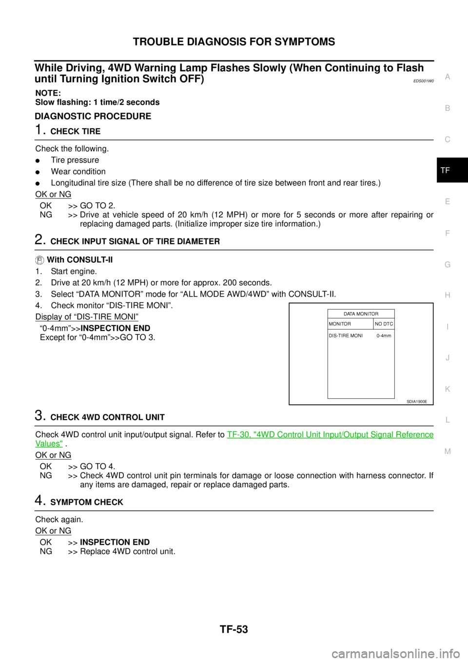
4. Check monitor “DIS-TIRE MONI”.
Display of
“DIS-TIRE MONI”
“0-4mm”>>INSPECTION END
Except for “0-4mm”>>GO TO 3.
3. CHECK 4WD CONTROL UNIT
Check 4WD control unit input/output signal. Refer to TF-30, "
4WD Control Unit Input/Output Signal Reference
Va l u e s" .
OK or NG
OK >> GO TO 4.
NG >> Check 4WD control unit pin terminals for damage or loose connection with harness connector. If
any items are damaged, repair or replace damaged parts.
4. SYMPTOM CHECK
Check again.
OK or NG
OK >>INSPECTION END
NG >> Replace 4WD control unit.
SDIA1900E
Page 2858 of 4555
TF-54
4WD CONTROL UNIT
4WD CONTROL UNITPFP:41650
Removal and InstallationEDS001W4
REMOVAL
1. Remove cluster lid “A”. Refer to IP-11, "Removal and Installation" .
2. Remove front speaker grille. Refer to IP-11, "
Removal and Installation" .
3. Remove driver box. Refer to IP-11, "
Removal and Installation" .
4. Disconnect 4WD control unit connector.
5. Remove 4WD control unit.
INSTALLATION
Install in the reverse order of removal.
SDIA1881E
Page 2902 of 4555
RFD-12
ELECTRIC CONTROLLED COUPLING
ELECTRIC CONTROLLED COUPLINGPFP:38760
Removal and InstallationEDS0027J
REMOVAL
1. Remove propeller shaft. Refer to PR-4, "Removal and Installation" .
2. Put matching mark on the thread edge of electric controlled cou-
pling. The matching mark should be in line with the matching
mark on the companion flange.
CAUTION:
For matching mark, use paint. Do not damage electric con-
trolled coupling.
NOTE:
When replacing electric controlled coupling, matching mark is
not necessary.
3. Remove companion flange lock nut, using a flange wrench.
4. Remove companion flange.
5. Disconnect 4WD solenoid harness connector and remove con-
nector bracket.
6. Remove electric controlled coupling breather hose from cou-
pling cover.
7. Remove coupling cover with electric controlled coupling from
carrier case.
8. Remove electric controlled coupling from coupling cover.
PDIA0455E
PDIA0456E
PDIA0458E
Page 2903 of 4555

ELECTRIC CONTROLLED COUPLING
RFD-13
C
E
F
G
H
I
J
K
L
MA
B
RFD
INSTALLATION
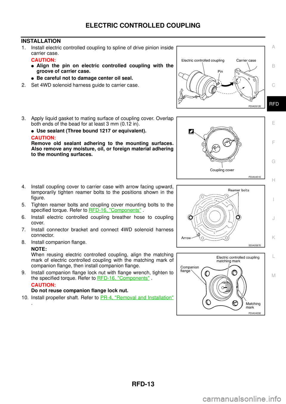
1. Install electric controlled coupling to spline of drive pinion inside
carrier case.
CAUTION:
�Align the pin on electric controlled coupling with the
groove of carrier case.
�Be careful not to damage center oil seal.
2. Set 4WD solenoid harness guide to carrier case.
3. Apply liquid gasket to mating surface of coupling cover. Overlap
both ends of the bead for at least 3 mm (0.12 in).
�Use sealant (Three bound 1217 or equivalent).
CAUTION:
Remove old sealant adhering to the mounting surfaces.
Also remove any moisture, oil, or foreign material adhering
to the mounting surfaces.
4. Install coupling cover to carrier case with arrow facing upward,
temporarily tighten reamer bolts to the positions shown in the
figure.
5. Tighten reamer bolts and coupling cover mounting bolts to the
specified torque. Refer to RFD-16, "
Components" .
6. Install electric controlled coupling breather hose to coupling
cover.
7. Install connector bracket and connect 4WD solenoid harness
connector.
8. Install companion flange.
NOTE:
When reusing electric controlled coupling, align the matching
mark of electric controlled coupling with the matching mark of
companion flange, then install companion flange.
9. Install companion flange lock nut with flange wrench, tighten to
the specified torque. Refer to RFD-16, "
Components" .
CAUTION:
Do not reuse companion flange lock nut.
10. Install propeller shaft. Refer to PR-4, "
Removal and Installation"
.
PDIA0912E
PDIA0451E
SDIA0587E
PDIA0455E
Page 2904 of 4555
RFD-14
REAR FINAL DRIVE ASSEMBLY
REAR FINAL DRIVE ASSEMBLYPFP:38300
Removal and InstallationEDS001ZA
REMOVAL
1. Remove propeller shaft. Refer to PR-4, "Removal and Installation" .
2. Remove drive shaft with power tool. Refer to RAX-14, "
Removal and Installation" .
3. Disconnect 4WD solenoid harness connector.
4. Remove rear final drive breather hose and electric controlled coupling breather hose.
5. Support rear final drive assembly with a suitable jack.
6. Remove rear final drive mounting nut at rear suspension mem-
ber.
7. Remove rear final drive mounting bolts at final drive mounting
bracket, and then remove rear final drive assembly.
If necessary, remove final drive mounting bracket.
CAUTION:
Secure rear final drive assembly to a suitable jack while
removing it.
1. Rear suspension member 2. Final drive mounting bracket 3. Harness bracket
4. Drive shaft 5. Propeller shaft 6. Rear final drive assembly
PDIA0433E
PDIA0434E
PDIA0435E
Page 2906 of 4555
RFD-16
REAR FINAL DRIVE ASSEMBLY
ComponentsEDS001ZB
PDIA0932E
1. Companion flange lock nut 2. Companion flange 3. Front oil seal
4. Coupling cover 5. Connector bracket 6. Reamer bolt
7. Coupling front bearing 8. Bearing shim 9. Electric controlled coupling
10. 4WD solenoid harness 11. Center oil seal 12. Drive pinion nut
13. Pinion front bearing 14. Carrier case 15. Collapsible spacer
16. Drive pinion adjusting shim 17. Pinion rear bearing 18. Drive pinion
19. Side oil seal 20. Side bearing adjusting shim 21. Side bearing
22. Drive gear 23. Differential case 24. Side gear thrust washer
25. Side gear 26. Pinion mate thrust washer 27. Pinion mate gear
28. Pinion mate shaft 29. Lock pin 30. Rear cover
31. Filler plug 32. Drain plug 33. Gasket
Page 2945 of 4555

RAX-1
REAR AXLE
D DRIVELINE/AXLE
CONTENTS
C
E
F
G
H
I
J
K
L
M
SECTION RAX
A
B
RAX
REAR AXLE
PRECAUTIONS .......................................................... 2
Caution ..................................................................... 2
PREPARATION ........................................................... 3
Special Service Tools (SST) ..................................... 3
NOISE, VIBRATION AND HARSHNESS (NVH)
TROUBLESHOOTING ................................................ 5
NVH Troubleshooting Chart ..................................... 5
WHEEL HUB (2WD) ................................................... 6
On-vehicle Inspection and Service ........................... 6
WHEEL BEARING INSPECTION ......................... 6
Removal and Installation .......................................... 6
COMPONENT ....................................................... 6
REMOVAL ............................................................. 6
INSPECTION AFTER REMOVAL ......................... 6
INSTALLATION ..................................................... 7
Disassembly and Assembly ..................................... 7
DISASSEMBLY ..................................................... 7
INSPECTION AFTER DISASSEMBLY ................. 8
ASSEMBLY ........................................................... 8
INSPECTION AFTER ASSEMBLY ....................... 8
WHEEL HUB (4WD) ................................................. 10On-Vehicle Inspection ............................................. 10
REAR WHEEL BEARING ................................... 10
Removal and Installation ........................................ 10
REMOVAL ........................................................... 11
INSTALLATION ................................................... 11
Disassembly and Assembly .................................... 11
DISASSEMBLY ................................................... 11
INSPECTION AFTER DISASSEMBLY ................ 12
ASSEMBLY ......................................................... 12
REAR DRIVE SHAFT ............................................... 14
Removal and Installation ........................................ 14
REMOVAL ........................................................... 14
INSPECTION AFTER REMOVAL ....................... 14
INSTALLATION ................................................... 14
Disassembly and Assembly .................................... 15
DISASSEMBLY ................................................... 15
INSPECTION AFTER DISASSEMBLY ................ 16
ASSEMBLY ......................................................... 16
SERVICE DATA AND SPECIFICATIONS (SDS) ...... 19
Wheel Bearing ........................................................ 19
Drive Shaft .............................................................. 19