Page 2954 of 4555
RAX-10
WHEEL HUB (4WD)
WHEEL HUB (4WD)PFP:43202
On-Vehicle InspectionEDS00065
Inspect to check that there is no excessive play, cracking, wear, or other damage to rear axle.
�Turn rear wheels (left/right) and check the play.
REAR WHEEL BEARING
With vehicle raised, inspect the following.
�Move wheel hub in the axial direction by hand. Check that there is no looseness of rear wheel bearing.
�Rotate wheel hub and check that there is no unusual noise or other irregular condition. If there are any
irregular condition, replace wheel bearing.
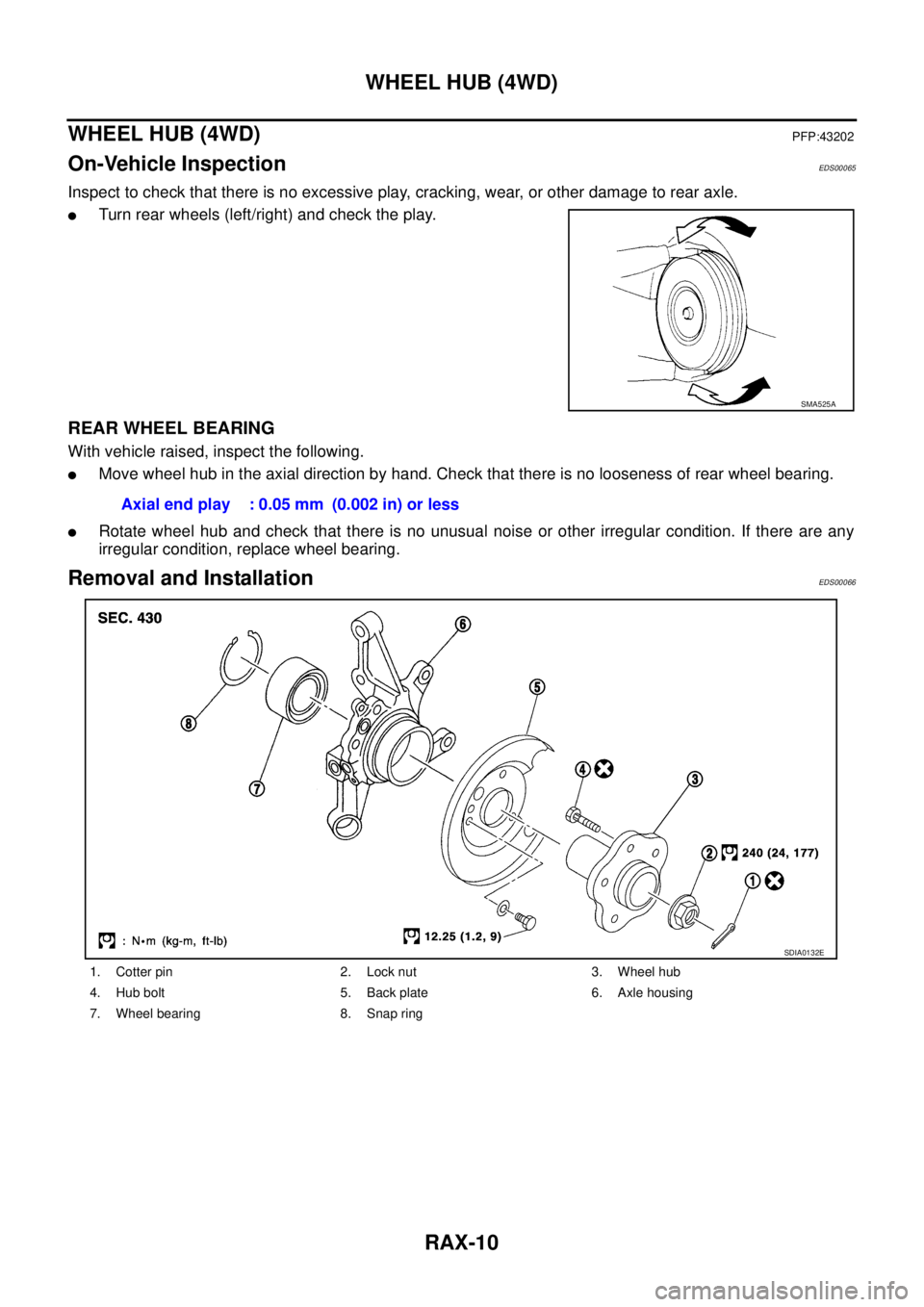
Removal and InstallationEDS00066
SMA525A
Axial end play : 0.05 mm (0.002 in) or less
1. Cotter pin 2. Lock nut 3. Wheel hub
4. Hub bolt 5. Back plate 6. Axle housing
7. Wheel bearing 8. Snap ring
SDIA0132E
Page 2955 of 4555

RAX-11
C
E
F
G
H
I
J
K
L
MA
B
RAX
REMOVAL
1. Remove tyre.
2. Remove wheel hub lock nut.
CAUTION:
Discard the old hub lock nut; replace with new one.
3. Remove brake caliper from axle")
WHEEL HUB (4WD)
RAX-11
C
E
F
G
H
I
J
K
L
MA
B
RAX
REMOVAL
1. Remove tyre.
2. Remove wheel hub lock nut.
CAUTION:
Discard the old hub lock nut; replace with new one.
3. Remove brake caliper from axle housing and hang it up some-
where.
CAUTION:
Avoid depressing the brake pedal while the brake caliper is
removed.
4. Remove disc rotor and parking brake assembly from back plate
and axle housing.
5. Remove wheel sensor from axle housing.
6. Remove axle housing from strut.
7. Remove nut and bolt from axle housing side of radius rod.
8. Remove nuts and bolts from axle housing side of front and rear parallel link. Remove axle housing from
vehicle.
INSTALLATION
�Refer to component parts drawing for tightening torque. For installation, follow removal procedure in
reverse order.
Disassembly and AssemblyEDS00067
DISASSEMBLY
1. Set axle housing on bench vise. As shown in the figure, use
attachment (SST) and sliding hammer (SST) to remove wheel
hub and bearing assembly from axle housing.
CAUTION:
When placing onto bench vise, be careful not to damage
strut mounting surface of steering knuckle. Use an alumi-
num plate or another suitable tool.
2. Use a bearing replacer (suitable tool), puller (suitable tool), and
drift (SST) to remove inner race of outer-wheel bearing from
wheel hub.
3. Remove back plate installation bolt and anchor block. Remove
back plate from axle housing. Refer to PB-4, "
Components"
4. Use a flat-bladed screwdriver or similar tool to remove snap ring.
SRA711A
FAC0104D
SDIA0154E
Page 2956 of 4555

5. Use a drift (SST) to remove wheel bearing from axle housing.
INSPECTION AFTER DISASSEMBLY
Wheel Hub
�Inspect wheel hub for deformation, cracks, and other damage. If any irr")
RAX-12
WHEEL HUB (4WD)
5. Use a drift (SST) to remove wheel bearing from axle housing.
INSPECTION AFTER DISASSEMBLY
Wheel Hub
�Inspect wheel hub for deformation, cracks, and other damage. If any irregular conditions are found,
replace wheel hub.
Axle Housing
�Inspect axle housing for deformation, cracks, and other damage. If any irregular conditions are found,
replace axle housing.
Snap Ring
�Check snap ring for deformation, cracks, and other damage. If any irregular conditions are found, replace
snap ring.
ASSEMBLY
1. Use a drift (SST) to press fit wheel bearing into axle housing.
CAUTION:
Discard the old wheel bearing; replace with a new one.
2. Use a flat-bladed screwdriver or similar tool to install the snap
ring.
3. Install back plate and anchor block onto axle housing. Refer to
PB-4, "
Components" .
4. Use a drift (SST) to install wheel hub onto axle housing.
5. After completing step 4, apply an additional load of 49,030 N
(5,000 kg, 11,025 lb). Rotate axle housing in forward and
reverse directions 10 times each to ensure a good fit.
6. Place a spring balance at the point where the strut is joined (upper side bolt hole) and measure rotating
torque when spring is pulled at a speed of 8 -12 rpm. Refer to the RAX-19, "
Wheel Bearing" item.
NOTE:
If a load of 49,030 N (5,000 kg, 11,025 lb) cannot be applied:
�Install to drive shaft and tighten wheel hub lock nut to specified torque. Rotate in forward and reverse
direction 10 times each to ensure a good fit.
�At a rotating speed of 8 - 12 rpm, place a spring balance on hub bolt and measure rotating torque.
SDIA0155E
SDIA1349E
SDIA0157E
Rotating torque : 1.96 N·m (0.20 kg-m, 17 in-lb) or less
Spring balance reading : 12.8 N (1.30 kg, 2.87 lb) or less
Page 2957 of 4555
WHEEL HUB (4WD)
RAX-13
C
E
F
G
H
I
J
K
L
MA
B
RAX
Rotating torque : 1.126 N·m (0.11 kg-m, 10 in-lb)
Spring balance reading : 19.70 N (2.01 kg, 4.43 lb)
Page 3034 of 4555

BR-36
REAR DISC BRAKE
2. Using a dial indicator, check run out.
NOTE:
Make sure that wheel bearing axial endplay is with in the specifi-
cation before measuring runout. Refer to RAX-6, "
On-vehicle
Inspection and Service" (2WD), RAX-10, "On-Vehicle Inspec-
tion" (4WD).
3. If the run out is outside the limit, find the minimum run out point by shifting the mounting positions of disc
rotor and wheel hub by one hole.
Thickness Inspection
Using a micrometer, check thickness of disc rotor. If the thickness is
outside the standard, replace disc rotor.
ASSEMBLY
CAUTION:
When assembling, do not use rubber grease.
1. Apply rubber lubricant to piston seals, and install them to the cyl-
inder body.
CAUTION:
Do not reuse piston seals.
2. Apply brake fluid to piston boots. Cover piston end with piston
boot. Install cylinder side boot lip properly into groove on cylin-
der body.
CAUTION:
Do not reuse piston boot.
3. Press piston into cylinder body by hand. Assemble piston side
boot lip properly into groove on the piston.
CAUTION:
Press piston evenly and change pressing point to prevent
the cylinder inner wall from being rubbed.Measurement point:
At a point of 10 mm (0.39 in) from the outer
edge of the disc.
Run out limit:
0.07 mm (0.0028 in) or less
BRA0013D
Standard thickness : 16.0 mm (0.630 in)
Wear limit : 14.0 mm (0.551 in)
Maximum uneven wear (measured at 8 positions):
0.02 mm (0.0008 in) or less
SBR020B
SFIA0156E
SFIA0157E
Page 3056 of 4555
![NISSAN X-TRAIL 2005 Service Repair Manual BRC-8
[ABS]
CAN COMMUNICATION
CAN COMMUNICATIONPFP:23710
System DescriptionEFS0067G
CAN (Controller Area Network) is a serial communication line for real time application. It is an on-vehicle mul-
t](/manual-img/5/57403/w960_57403-3055.png "NISSAN X-TRAIL 2005 Service Repair Manual BRC-8
[ABS]
CAN COMMUNICATION
CAN COMMUNICATIONPFP:23710
System DescriptionEFS0067G
CAN (Controller Area Network) is a serial communication line for real time application. It is an on-vehicle mul-
t")
BRC-8
[ABS]
CAN COMMUNICATION
CAN COMMUNICATIONPFP:23710
System DescriptionEFS0067G
CAN (Controller Area Network) is a serial communication line for real time application. It is an on-vehicle mul-
tiplex communication line with high data communication speed and excellent error detection ability. Many elec-
tronic control units are equipped onto a vehicle, and each control unit shares information and links with other
control units during operation (not independent). In CAN communication, control units are connected with 2
communication lines (CAN H line, CAN L line) allowing a high rate of information transmission with less wiring.
Each control unit transmits/receives data but selectively reads required data only.
CAN Communication UnitEFS0067H
TYPE 1/TYPE 2
System diagram
Input/output signal chart
T: Transmit R: Receive Body typeWagon
Axle 4WD 2WD
Engine YD22DDTi QR20DE/QR25DE QR20DE YD22DDTi
Transmission M/T A/T M/T
Brake controlABS
CAN system type 1 2 3 7 8
ECM×××××
TCM×
ESP/TCS/ABS control unit
ABS actuator and electric unit (control unit)×××××
Steering angle sensor
4WD control unit×××
Combination meter×××××
PKIA6458E
Signals ECMABS actuator and
electric unit
(control unit)4WD control unit Combination meter
4WD mode indicator lamp signal T R
4WD warning lamp signalTR
Page 3057 of 4555
CAN COMMUNICATION
BRC-9
[ABS]
C
D
E
G
H
I
J
K
L
MA
B
BRC
*: YD engine models only
TYPE 3
System diagram
Input/output signal chart
T: Transmit R: Receive A/C compressor feedback signal T R
ABS warning lamp signal T R
Accelerator pedal position signal T R
Engine coolant temperature signal T R
Engine speed signal T R R
MI signal T R
Parking brake switch signalRT
Stop lamp switch signal T R
Vehicle speed signalTRR
RT
ASCD SET lamp signal T R
ASCD CRUISE lamp signal T R
Stop lamp switch signal T R
Glow indicator lamp signal* T R
A/C switch signal* R TSignals ECMABS actuator and
electric unit
(control unit)4WD control unit Combination meter
PKIA6457E
Signals ECM TCMABS actuator
and electric unit
(control unit)4WD control
unitCombination
meter
4WD mode indicator lamp signalTR
4WD warning lamp signalTR
A/C compressor feedback signal TR
A/T position indicator lamp signal T R
A/T self-diagnosis signal R T
ABS warning lamp signal T R
Page 3058 of 4555
BRC-10
[ABS]
CAN COMMUNICATION
TYPE 7/TYPE 8
System diagram
Input/output signal chart
T: Transmit R: Receive Accelerator pedal position signal T R
Closed throttle position signal T R
Engine A/T integrated control signalTR
RT
Engine coolant temperature signal TR
Engine speed signal T R R
MI signal TR
O/D OFF indicator signal T R
Output shaft revolution signal R T
Overdrive control switch signal R T
P·N range signal R T
Parking brake switch signalRT
Stop lamp switch signalRT
TR
Vehicle speed signalTRR
RT
Wide open throttle position signal T R
ASCD SET lamp signal TR
ASCD CRUISE lamp signal TR Signals ECM TCMABS actuator
and electric unit
(control unit)4WD control
unitCombination
meter
SKIA9999E
Signals ECM ABS actuator and electric unit (control unit) Combination meter
A/C compressor feedback signal T R
ABS warning lamp signal T R
Engine coolant temperature signal T R
Engine speed signal T R

RAX-13
C
E
F
G
H
I
J
K
L
MA
B
RAX
Rotating torque : 1.126 N·m (0.11 kg-m, 10 in-lb)
Spring balance reading : 19.70 N (2.01 kg, 4.43 lb)")
![NISSAN X-TRAIL 2005 Service Repair Manual CAN COMMUNICATION
BRC-9
[ABS]
C
D
E
G
H
I
J
K
L
MA
B
BRC
*: YD engine models only
TYPE 3
System diagram
Input/output signal chart
T: Transmit R: Receive A/C compressor feedback signal T R
ABS warn](/manual-img/5/57403/w960_57403-3056.png "NISSAN X-TRAIL 2005 Service Repair Manual CAN COMMUNICATION
BRC-9
[ABS]
C
D
E
G
H
I
J
K
L
MA
B
BRC
*: YD engine models only
TYPE 3
System diagram
Input/output signal chart
T: Transmit R: Receive A/C compressor feedback signal T R
ABS warn")
![NISSAN X-TRAIL 2005 Service Repair Manual BRC-10
[ABS]
CAN COMMUNICATION
TYPE 7/TYPE 8
System diagram
Input/output signal chart
T: Transmit R: Receive Accelerator pedal position signal T R
Closed throttle position signal T R
Engine A/T](/manual-img/5/57403/w960_57403-3057.png "NISSAN X-TRAIL 2005 Service Repair Manual BRC-10
[ABS]
CAN COMMUNICATION
TYPE 7/TYPE 8
System diagram
Input/output signal chart
T: Transmit R: Receive Accelerator pedal position signal T R
Closed throttle position signal T R
Engine A/T")