Page 2487 of 3171
MTC-100
BLOWER MOTOR
BLOWER MOTOR
PFP:27226
ComponentsEJS005GU
Removal and InstallationEJS005GV
REMOVAL
1. Remove the glove box assembly. Refer toIP-15, "LOWER INSTRUMENT PANEL RH AND GLOVE BOX"
.
2. Disconnect the blower motor electrical connector.
3. Remove the three screws and remove the blower motor.
INSTALLATION
Installation is in the reverse order of removal.
1. Heater and cooling unit assembly 2. Blower motor 3. Blower motor resistor
MJIB0247E
Page 2488 of 3171

AIR CONDITIONER FILTER
MTC-101
C
D
E
F
G
H
I
K
L
MA
B
MTC
AIR CONDITIONER FILTERPFP:27277
Removal and InstallationEJS005GW
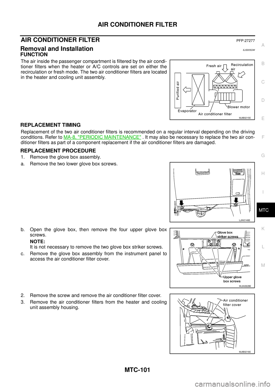
FUNCTION
The air inside the passenger compartment is filtered by the air condi-
tioner filters when the heater or A/C controls are set on either the
recirculation or fresh mode. The two air conditioner filters are located
in the heater and cooling unit assembly.
REPLACEMENT TIMING
Replacement of the two air conditioner filters is recommended on a regular interval depending on the driving
conditions. Refer toMA-8, "
PERIODIC MAINTENANCE". It may also be necessary to replace the two air con-
ditioner filters as part of a component replacement if the air conditioner filters are damaged.
REPLACEMENT PROCEDURE
1. Remove the glove box assembly.
a. Remove the two lower glove box screws.
b. Open the glove box, then remove the four upper glove box
screws.
NOTE:
It is not necessary to remove the two glove box striker screws.
c. Remove the glove box assembly from the instrument panel to
access the air conditioner filter cover.
2. Remove the screw and remove the air conditioner filter cover.
3. Remove the air conditioner filters from the heater and cooling
unit assembly housing.
MJIB0215E
LJIA0146E
WJIA0628E
MJIB0216E
Page 2489 of 3171
MTC-102
AIR CONDITIONER FILTER
4. Insert the first new air conditioner filter into the heater and cool-
ing unit assembly housing and slide it over to the right. Insert the
second new air conditioner filter into the heater and cooling unit
assembly housing.
NOTE:
The air conditioner filters are marked with air flow arrows. The
end of the microfilter with the arrow should face the rear of the
vehicle. The arrows should point downward.
5. Install the air conditioner filter cover.
6. Install the glove box assembly in reverse order of removal.
LJIA0148E
MJIB0216E
Lower glove box screws : 3.5 N·m (0.36 kg-m, 31 in-lb)
Upper glove box screws : 3.5 N·m (0.36 kg-m, 31 in-lb)
Page 2949 of 3171

SRS-40
FRONT PASSENGER AIR BAG MODULE
FRONT PASSENGER AIR BAG MODULE
PFP:K8515
Removal and InstallationEHS001XU
The passenger air bag module originally installed in the vehicle uses direct-connect style harness connectors.
Service replacement passenger air bag modules use tab-locking style harness connectors. If the passenger
air bag module is replaced or if the direct-connect harness connectors are damaged, the vehicle wiring har-
ness must be modified to allow connection of the service replacement passenger air bag module. Refer to
SRS-41, "
WIRING HARNESS MODIFICATION"for wiring harness modification procedure.
REMOVAL
CAUTION:
lDo not attempt to repair or replace damaged direct-connect front passenger air bag module con-
nectors. If a direct-connect harness connector is damaged, the front passenger air bag must be
replaced and the wiring harness modified.
lBefore servicing SRS, turn the ignition switch off, disconnect both battery cables and wait at least
3 minutes.
lAlways work from the side of or under front passenger air bag module.
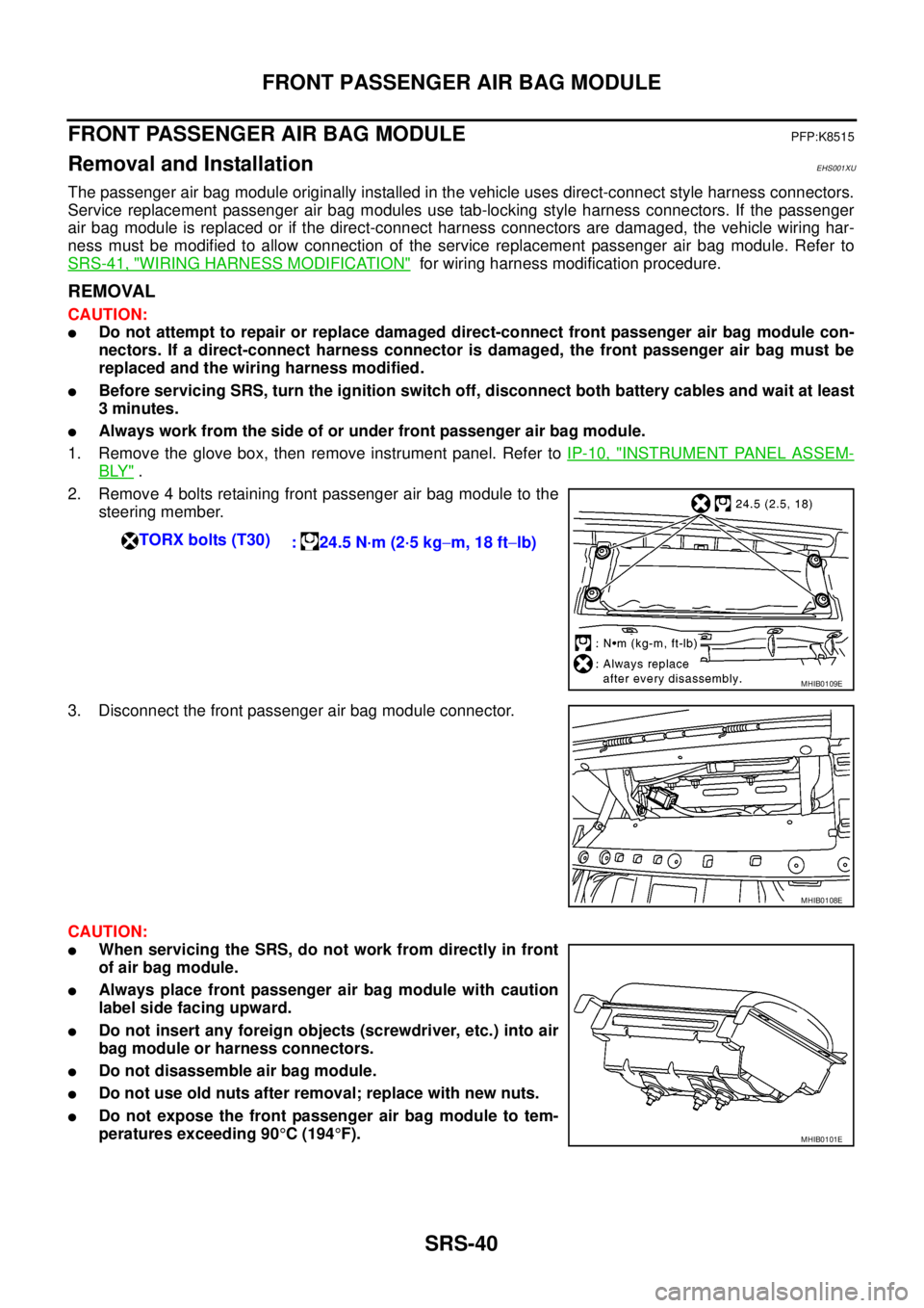
1. Remove the glove box, then remove instrument panel. Refer toIP-10, "
INSTRUMENT PANEL ASSEM-
BLY".
2. Remove 4 bolts retaining front passenger air bag module to the
steering member.
3. Disconnect the front passenger air bag module connector.
CAUTION:
lWhen servicing the SRS, do not work from directly in front
of air bag module.
lAlways place front passenger air bag module with caution
label side facing upward.
lDo not insert any foreign objects (screwdriver, etc.) into air
bag module or harness connectors.
lDo not disassemble air bag module.
lDo not use old nuts after removal; replace with new nuts.
lDo not expose the front passenger air bag module to tem-
peratures exceeding 90°C(194°F). TORX bolts (T30)
: 24.5 N·m (2·5 kg-m, 18 ft-lb)
MHIB0109E
MHIB0108E
MHIB0101E
Page 3167 of 3171
WW-56
CIGARETTE LIGHTER
Removal and Installation of Cigarette Lighter
EKS00P6M
REMOVAL
1. Remove lower glove box assembly. Refer toIP-10, "INSTRUMENT PANEL ASSEMBLY".
2. Disconnect cigarette lighter connector.
3. Remove cigalette lighter (1).
4. Remove inner socket (2) from ring (3), while pressing hook (A)
on ring (3) out from square hole (B).
5. Remove ring (3) from cluster lid D, while pressing pawls (C).
INSTALLATION
Note the following, and installation is the reverse order of removal.
CAUTION:
Align notches of ring and cluster lid D when installing.
SKIB6859E
Page 3169 of 3171
WW-58
POWER SOCKET
Removal and Installation of Front Power Socket
EKS00P6O
REMOVAL
1. Remove lower glove box assembly. Refer toIP-10, "INSTRUMENT PANEL ASSEMBLY".
2. Disconnect power socket connector.
3. Remove inner socket (1) and ring (2) from cluster lid D, while
pressing pawls (A).
4. Remove inner socket (1) from ring (2), while pressing the hook
(B) on ring (2) out from square hole (C).
INSTALLATION
Note the following, and installation is the reverse order of removal.
CAUTION:
Align notches of ring and cluster lid D when installing.
Removal and Installation of Console Power SocketEKS00P6P
REMOVAL
1. Remove inner socket from ring, while pressing the hook on ring
out from square hole.
2. Disconnect power socket connector.
3. Remove ring from power socket finisher, while pressing pawls.
INSTALLATION
Note the following, and installation is the reverse order of removal.
CAUTION:
Align notches of ring and cluster lid D when installing.
SKIB6448E
WKIA1035E
Page:
< prev 1-8 9-16 17-24