Page 1760 of 3171

IP-1
INSTRUMENT PANEL
IBODY
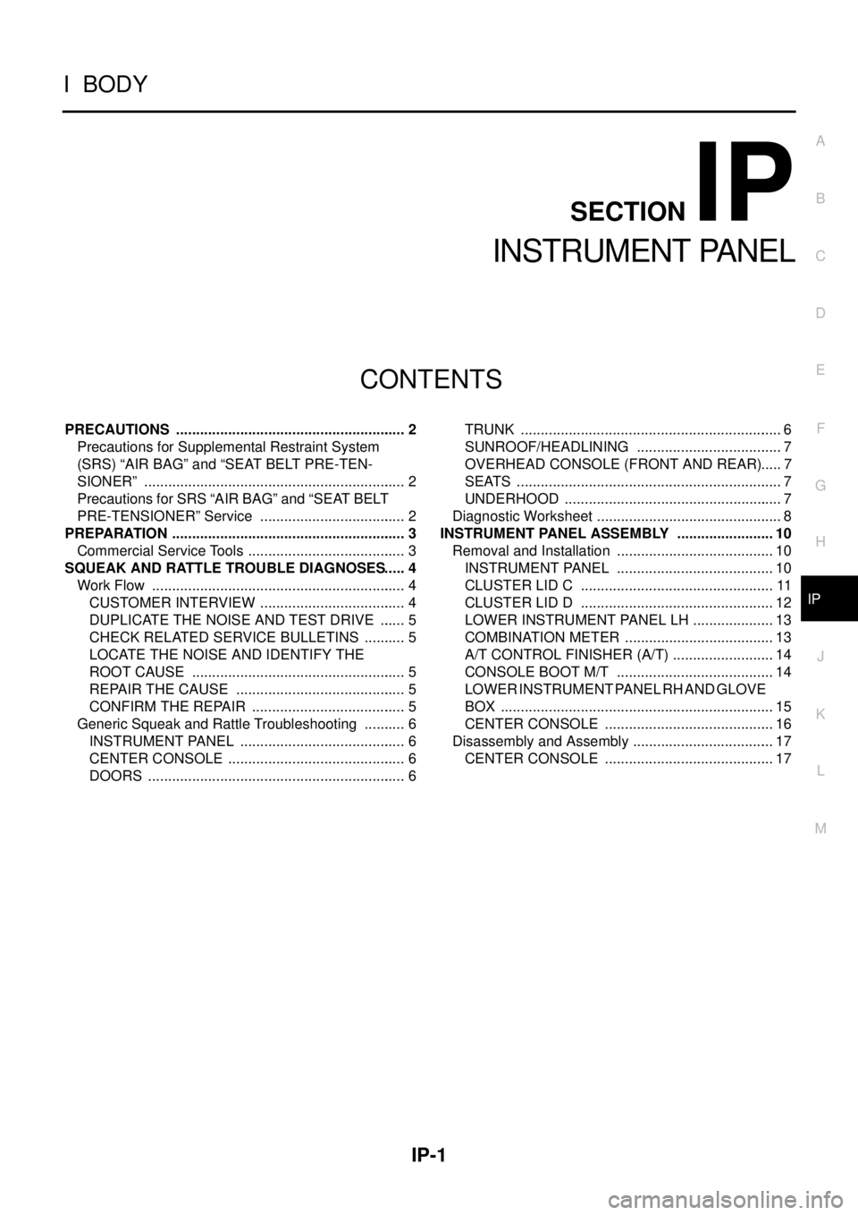
CONTENTS
C
D
E
F
G
H
J
K
L
M
SECTIONIP
A
B
IP
INSTRUMENT PANEL
PRECAUTIONS .......................................................... 2
Precautions for Supplemental Restraint System
(SRS)“AIRBAG”and“SEATBELTPRE-TEN-
SIONER” .................................................................. 2
Precautions for SRS “AIR BAG” and “SEAT BELT
PRE-TENSIONER” Service ..................................... 2
PREPARATION ........................................................... 3
Commercial Service Tools ........................................ 3
SQUEAK AND RATTLE TROUBLE DIAGNOSES..... 4
Work Flow ................................................................ 4
CUSTOMER INTERVIEW ..................................... 4
DUPLICATE THE NOISE AND TEST DRIVE ....... 5
CHECK RELATED SERVICE BULLETINS ........... 5
LOCATE THE NOISE AND IDENTIFY THE
ROOT CAUSE ...................................................... 5
REPAIR THE CAUSE ........................................... 5
CONFIRM THE REPAIR ....................................... 5
Generic Squeak and Rattle Troubleshooting ........... 6
INSTRUMENT PANEL .......................................... 6
CENTER CONSOLE ............................................. 6
DOORS ................................................................. 6TRUNK .................................................................. 6
SUNROOF/HEADLINING ..................................... 7
OVERHEAD CONSOLE (FRONT AND REAR)..... 7
SEATS ................................................................... 7
UNDERHOOD ....................................................... 7
Diagnostic Worksheet ............................................... 8
INSTRUMENT PANEL ASSEMBLY ......................... 10
Removal and Installation ........................................ 10
INSTRUMENT PANEL ........................................ 10
CLUSTER LID C ................................................. 11
CLUSTER LID D ................................................. 12
LOWER INSTRUMENT PANEL LH ..................... 13
COMBINATION METER ...................................... 13
A/T CONTROL FINISHER (A/T) .......................... 14
CONSOLE BOOT M/T ........................................ 14
LOWER INSTRUMENT PANEL RH AND GLOVE
BOX ..................................................................... 15
CENTER CONSOLE ........................................... 16
Disassembly and Assembly .................................... 17
CENTER CONSOLE ........................................... 17
Page 1769 of 3171
IP-10
INSTRUMENT PANEL ASSEMBLY
INSTRUMENT PANEL ASSEMBLY
PFP:68200
Removal and InstallationEIS00DYZ
INSTRUMENT PANEL
Removal
1. Display unit bracket RH/LH 2. Cluster lid A 3. Front passenger air bag module
4. Speaker grille RH/LH 5. Instrument panel 6. Instrument side finisher
7. Side ventilator grille RH/LH 8. Upper glove box 9. Upper glove box door
10. Lower glove box damper assembly 11. Lower instrument panel RH 12. Fuse block cover
13. Lower glove box assembly 14. Liner 15. Cluster lid D
16. Audio unit 17. NAVI/Audio control panel 18. Audio unit bracket RH/LH
19. Display unit 20. Storage tray (If equipped) 21. Cluster lid C
22. Center ventilator grille RH/LH 23. Steering column cover (lower) 24. Steering column cover upper
25. Steering lock escutcheon 26. Combination meter 27. GPS Antenna
MIIB9138E
Page 1771 of 3171
IP-12
INSTRUMENT PANEL ASSEMBLY
Removal - with NAVI
1. Remove A/T control finisher, or console boot M/T. Refer toIP-14, "A/T CONTROL FINISHER (A/T)",or
Refer toIP-14, "
CONSOLE BOOT M/T".
2. Pull cluster lid C rearward to release clips.
3. Disconnect electrical connectors and remove cluster lid C.
Installation - with NAVI
Installation is in the reverse order of removal.
CLUSTER LID D
Removal
1. Remove center console. Refer toIP-16, "CENTER CONSOLE".
2. Remove lower instrument panel LH. Refer toIP-13, "
LOWER INSTRUMENT PANEL LH".
3. Remove glove box lower. Refer toIP-15, "
LOWER INSTRUMENT PANEL RH AND GLOVE BOX".
4. Disconnect the electrical connectors and remove cluster lid D.
Installation
Installation is in the reverse order of removal.
1. Instrument panel 2. Cluster lid C
MIIB9079E
WIIA0564E
1. Cluster lid D 2. Screws
Page 1774 of 3171

INSTRUMENT PANEL ASSEMBLY
IP-15
C
D
E
F
G
H
J
K
L
MA
B
IP
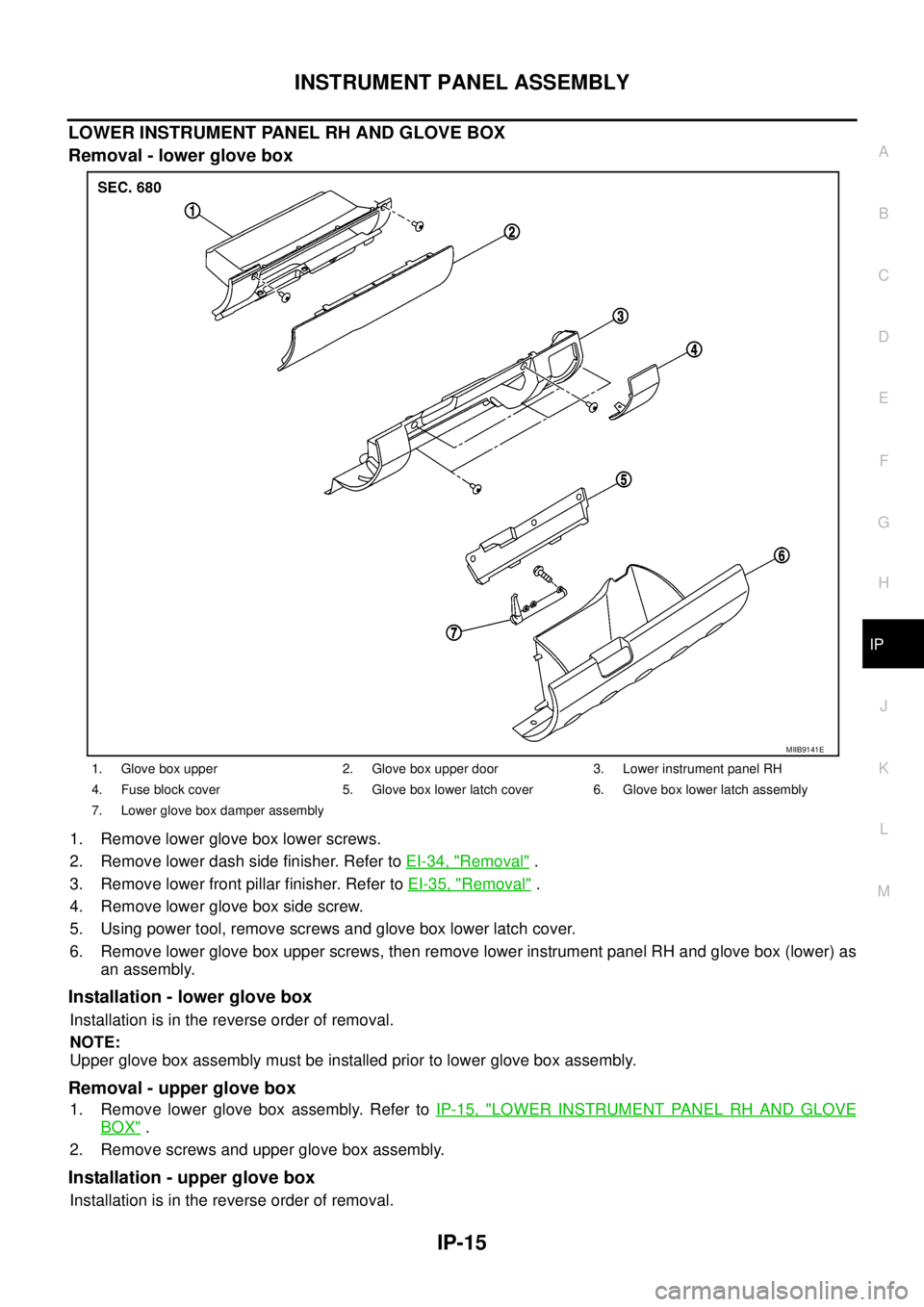
LOWER INSTRUMENT PANEL RH AND GLOVE BOX
Removal - lower glove box
1. Remove lower glove box lower screws.
2. Remove lower dash side finisher. Refer toEI-34, "
Removal".
3. Remove lower front pillar finisher. Refer toEI-35, "
Removal".
4. Remove lower glove box side screw.
5. Using power tool, remove screws and glove box lower latch cover.
6. Remove lower glove box upper screws, then remove lower instrument panel RH and glove box (lower) as
an assembly.
Installation - lower glove box
Installation is in the reverse order of removal.
NOTE:
Upper glove box assembly must be installed prior to lower glove box assembly.
Removal - upper glove box
1. Remove lower glove box assembly. Refer toIP-15, "LOWER INSTRUMENT PANEL RH AND GLOVE
BOX".
2. Remove screws and upper glove box assembly.
Installation - upper glove box
Installation is in the reverse order of removal.
1. Glove box upper 2. Glove box upper door 3. Lower instrument panel RH
4. Fuse block cover 5. Glove box lower latch cover 6. Glove box lower latch assembly
7. Lower glove box damper assembly
MIIB9141E
Page 1775 of 3171
IP-16
INSTRUMENT PANEL ASSEMBLY
CENTER CONSOLE
Removal
1. Remove cup holder finisher.
2. Remove A/T or M/T finisher. Refer toIP-14, "
A/T CONTROL FINISHER (A/T)".
3. Remove RH lower glove box assembly.
4. Remove center console screws.
5. Release center console, rear base, from front base.
6. Disconnect electrical connectors and remove center console.
Installation
Installation is in the reverse order of removal.
1. Center console front base. 2. Center console rear base.
MIIB9142E
Page 2245 of 3171

LT-162
ILLUMINATION
ILLUMINATION
PFP:27545
System DescriptionEKS00P8V
Control of the illumination lamps operation is dependent upon the position of the lighting switch (combination
switch). When the lighting switch is placed in the 1ST position, 2ND position or AUTO position (headlamp is
ON) the BCM (body control module) receives input signal requesting the illumination lamps to illuminate. This
input signal is communicated to the IPDM E/R (intelligent power distribution module engine room) through the
CAN communication. The CPU (central processing unit) of the IPDM E/R controls the tail lamp relay coil. This
relay, when energized, directs power to the illumination lamps, which then illuminate.
Power is supplied at all times
lto ignition relay (located in IPDM E/R) and
lto tail lamp relay (located in IPDM E/R), from battery directly,
lthrough 50A fusible link (letter G, located in fuse and fusible link box)
lto BCM terminal 57,
lthrough 20A fuse (No. 52, located in IPDM E/R) and
lthrough 20A fuse (No. 53, located in IPDM E/R)
lto CPU (located in IPDM E/R),
lthrough 10A fuse [No.19, located in fuse block (J/B)]
lto combination meter terminal 3.
With the ignition switch in the ON or START position, power is supplied
lto ignition relay (located in IPDM E/R),
lthrough 10A fuse [No. 1, located in fuse block (J/B)]
lto BCM terminal 3,
lthrough 10A fuse [No. 14, located in fuse block (J/B)]
lto combination meter 16.
Ground is supplied
lto BCM terminal 55 and
lto combination meter terminal 23
lthrough grounds M21, M80 and M83,
lto IPDM E/R terminals 38 and 59
lthrough grounds E21, E41 and E61.
ILLUMINATION OPERATION BY LIGHTING SWITCH
With the lighting switch in the 1ST position, 2ND position or AUTO position (headlamp is ON), the BCM
receives input signal requesting the illumination lamps to illuminate. This input signal is communicated to the
IPDM E/R through the CAN communication. The CPU of the IPDM E/R controls the tail lamp relay coil, which,
when energized, directs power
lthrough 10A fuse (No. 37, located in IPDM E/R)
lthrough IPDM E/R terminal 57
lto hazard switch (illumination) terminal 3
lto 4WD shift switch (illumination) terminal 7 (with 4-wheel drive)
lto front air control (illumination) terminal 8
lto audio unit (illumination) terminal 2 (1CD player)
lto audio unit (illumination) terminal 8 (6CD player)
lto AV switch (illumination) terminal 3 (with NAVI)
lto audio unit (illumination) terminal 29 (with NAVI)
lto glove box lamp terminal 1
lto A/T device (illumination) terminal 3 (with A/T)
lto heat up switch (illumination) terminal 5
lto DIFF LOCK switch (illumination) terminal 4 (with DIFF LOCK)
lto heated seat switch (driver side) (illumination) terminal 5 (with heated seats)
lto heated seat switch (passenger side) (illumination) terminal 5 (with heated seats)
Page 2246 of 3171

ILLUMINATION
LT-163
C
D
E
F
G
H
I
J
L
MA
B
LT
lto cigarette lighter (illumination) terminal 1
lto ashtray (illumination) terminal 1
lto headlamp washer switch (illumination) terminal 3
lto headlamp aiming switch (illumination) terminal 3 and
lto NAVI control unit (illumination) terminal 61 (with NAVI).
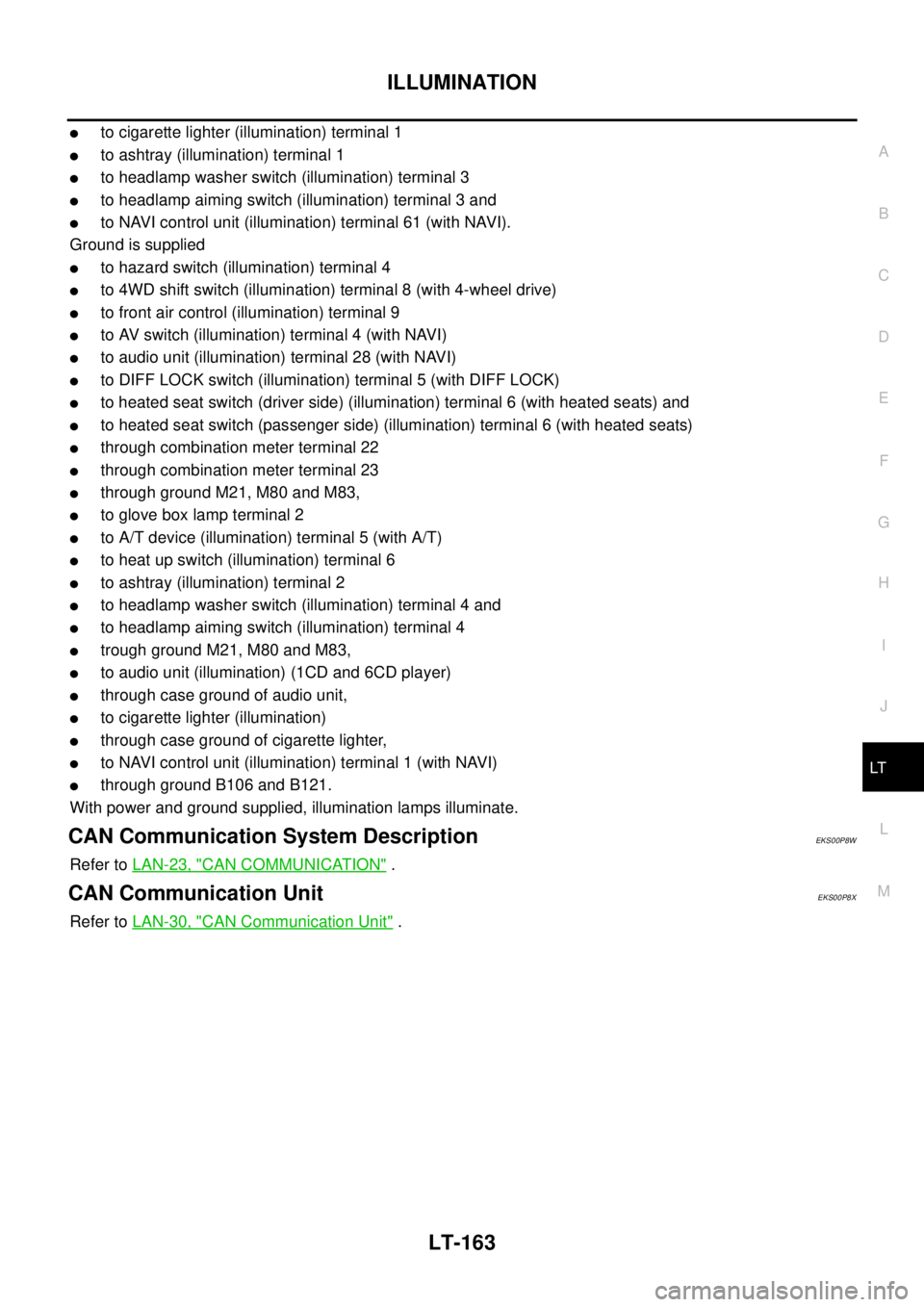
Ground is supplied
lto hazard switch (illumination) terminal 4
lto 4WD shift switch (illumination) terminal 8 (with 4-wheel drive)
lto front air control (illumination) terminal 9
lto AV switch (illumination) terminal 4 (with NAVI)
lto audio unit (illumination) terminal 28 (with NAVI)
lto DIFF LOCK switch (illumination) terminal 5 (with DIFF LOCK)
lto heated seat switch (driver side) (illumination) terminal 6 (with heated seats) and
lto heated seat switch (passenger side) (illumination) terminal 6 (with heated seats)
lthrough combination meter terminal 22
lthrough combination meter terminal 23
lthrough ground M21, M80 and M83,
lto glove box lamp terminal 2
lto A/T device (illumination) terminal 5 (with A/T)
lto heat up switch (illumination) terminal 6
lto ashtray (illumination) terminal 2
lto headlamp washer switch (illumination) terminal 4 and
lto headlamp aiming switch (illumination) terminal 4
ltrough ground M21, M80 and M83,
lto audio unit (illumination) (1CD and 6CD player)
lthrough case ground of audio unit,
lto cigarette lighter (illumination)
lthrough case ground of cigarette lighter,
lto NAVI control unit (illumination) terminal 1 (with NAVI)
lthrough ground B106 and B121.
With power and ground supplied, illumination lamps illuminate.
CAN Communication System DescriptionEKS00P8W
Refer toLAN-23, "CAN COMMUNICATION".
CAN Communication UnitEKS00P8X
Refer toLAN-30, "CAN Communication Unit".
Page 2256 of 3171
BULB SPECIFICATIONS
LT-173
C
D
E
F
G
H
I
J
L
MA
B
LT
BULB SPECIFICATIONSPFP:26297
HeadlampEKS00P82
Exterior LampEKS00P83
Interior Lamp/IlluminationEKS00P84
Item Wattage (W)
High/Low60/55 (H4LL)
Item Wattage (W)
Front combination lampTurn signal lamp 21
Clearance lamp 5
Rear combination lampStop/Tail lamp 21/5
Turn signal lamp 21
Back- up lamp 16
Rear fog lamp 21
Side turn signal lamp5
Front fog lamp55
License plate lamp5
Item Wattage (W)
Glove box lamp3.4
Room/Map lamp6
A/T device lamp3