Page 2228 of 3171

INTERIOR ROOM LAMP
LT-145
C
D
E
F
G
H
I
J
L
MA
B
LT
INTERIOR ROOM LAMPPFP:26410
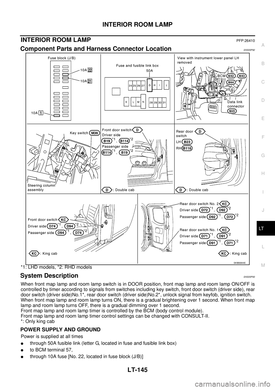
Component Parts and Harness Connector LocationEKS00P92
*1: LHD models, *2: RHD models
System DescriptionEKS00P93
When front map lamp and room lamp switch is in DOOR position, front map lamp and room lamp ON/OFF is
controlled by timer according to signals from switches including key switch, front door switch (driver side), rear
door switch (driver side)No.1*, rear door switch (driver side)No.2*, unlock signal from keyfob, ignition switch.
When front map lamp and room lamp turns ON, there is a gradual brightening over 1 second. When front map
lamp and room lamp turns OFF, there is a gradual dimming over 1 second.
Front map lamp and room lamp timer is controlled by the BCM (body control module).
Front map lamp and room lamp timer control settings can be changed with CONSULT-II.
*: Only king cab
POWER SUPPLY AND GROUND
Power is supplied at all times
lthrough 50A fusible link (letter G, located in fuse and fusible link box)
lto BCM terminal 57,
lthrough 10A fuse [No. 22, located in fuse block (J/B)]
SKIB6844E
Page 2531 of 3171

PG-2
REAR DOOR LH HARNESS/KING CAB MOD-
ELS ...................................................................... 66
REAR DOOR RH HARNESS/KING CAB MOD-
ELS ...................................................................... 66
TAIL HARNESS ................................................... 67
Wiring Diagram Codes (Cell Codes) ....................... 68
ELECTRICAL UNITS LOCATION ............................. 71
Electrical Units Location ......................................... 71
ENGINE COMPARTMENT .................................. 71
PASSENGER COMPARTMENT .......................... 72
Fuse ........................................................................ 74
Fusible Link ............................................................ 74
Circuit Breaker (Built Into BCM) ............................. 74
HARNESS CONNECTOR ......................................... 75
Description .............................................................. 75
HARNESS CONNECTOR (TAB-LOCKING
TYPE) .................................................................. 75
HARNESS CONNECTOR (SLIDE-LOCKINGTYPE) .................................................................. 76
HARNESS CONNECTOR (DIRECT-CONNECT
SRS COMPONENT TYPE) .................................. 77
ELECTRICAL UNITS ................................................ 78
Terminal Arrangement ............................................. 78
STANDARDIZED RELAY .......................................... 79
Description .............................................................. 79
NORMAL OPEN, NORMAL CLOSED AND
MIXED TYPE RELAYS ........................................ 79
TYPE OF STANDARDIZED RELAYS .................. 79
SUPER MULTIPLE JUNCTION (SMJ) ...................... 81
Terminal Arrangement ............................................. 81
FUSE BLOCK - JUNCTION BOX (J/B) .................... 83
Terminal Arrangement ............................................. 83
FUSE AND FUSIBLE LINK BOX .............................. 84
Terminal Arrangement ............................................. 84
FUSE AND RELAY BOX ........................................... 85
Terminal Arrangement ............................................. 85
Page 2687 of 3171
RF-10
SUNROOF
SUNROOF
PFP:91210
Component Parts and Harness Connector LocationEIS00D4V
MIIB0864E
1. Fuse block (J/B) fuse layout 2. Fuse and fusible link box 3. BCM M42,M43
(View with instrument lower panel LH
removed.)
4. Sunroof motor assembly B16 5. Sunroof switch R5
Page 2693 of 3171

RF-16
SUNROOF
Work Flow
EIS00D52
1. Check the symptom and customer's requests.
2. Understand the outline of system. Refer toRF-11, "
System Description".
3. According to the trouble diagnosis chart, repair or replace the cause of the malfunction. Refer toRF-16,
"Trouble Diagnosis Symptom Chart".
4. Does sunroof system operate normally? If Yes, GO TO 5. If No, GO TO 3.
5. INSPECTION END.
Trouble Diagnosis Symptom ChartEIS00D53
BCM Power Supply and Ground Circuit CheckEIS00D54
1.FUSE INSPECTION
Check the following.
l50A fusible link (letterG, located in the fuse and fusible link box)
l10A fuse [No. 1, located in the fuse block (J/B)]
l10A fuse [No.21 located in the fuse block (J/B)]
NOTE:
Refer toRF-10, "
Component Parts and Harness Connector Location".
OK or NG
OK >> GO TO 2.
NG >> If fuse is blown, be sure to eliminate cause of malfunction before installing new fuse, refer toPG-
4, "POWER SUPPLY ROUTING CIRCUIT".
2.CHECK POWER SUPPLY CIRCUIT
1. Turn ignition switch OFF.
2. Disconnect BCM connector.
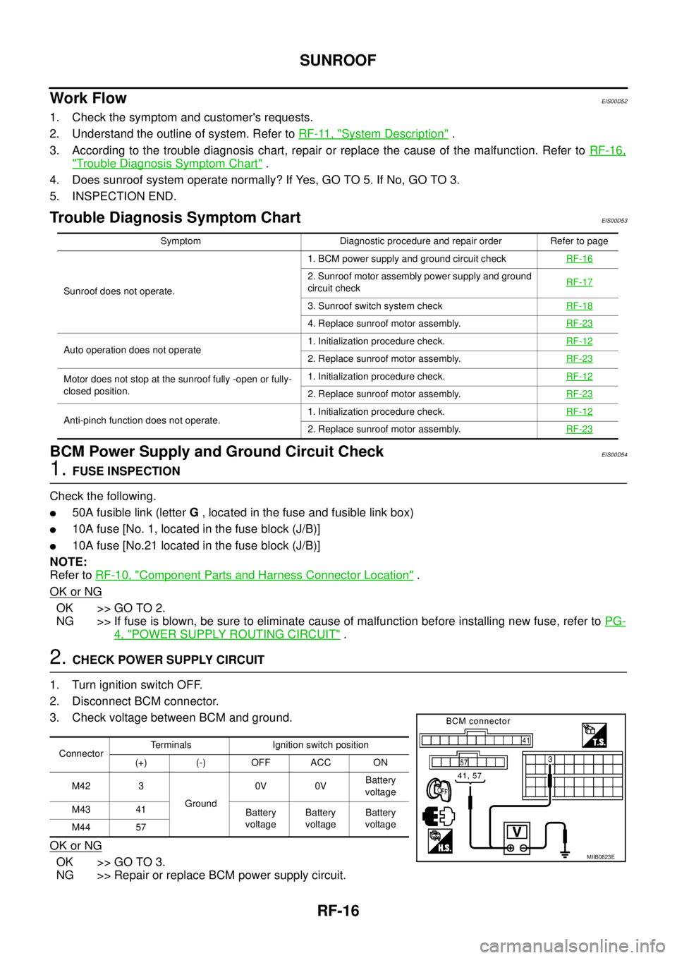
3. Check voltage between BCM and ground.
OK or NG
OK >> GO TO 3.
NG >> Repair or replace BCM power supply circuit.
Symptom Diagnostic procedure and repair order Refer to page
Sunroof does not operate.1. BCM power supply and ground circuit checkRF-16
2. Sunroof motor assembly power supply and ground
circuit checkRF-17
3. Sunroof switch system checkRF-18
4. Replace sunroof motor assembly.RF-23
Auto operation does not operate1. Initialization procedure check.RF-122. Replace sunroof motor assembly.RF-23
Motor does not stop at the sunroof fully -open or fully-
closed position.1. Initialization procedure check.RF-12
2. Replace sunroof motor assembly.RF-23
Anti-pinch function does not operate.1. Initialization procedure check.RF-122. Replace sunroof motor assembly.RF-23
ConnectorTerminals Ignition switch position
(+) (-) OFF ACC ON
M42 3
Ground0V 0VBattery
voltage
M43 41
Battery
voltageBattery
voltageBattery
voltage
M44 57
MIIB0823E
Page 3115 of 3171
WW-4
FRONT WIPER AND WASHER SYSTEM
FRONT WIPER AND WASHER SYSTEM
PFP:28810
Components Parts and Harness Connector LocationEKS00P4U
System DescriptionEKS00P4V
lAll front wiper relays (MAIN, LOW/HIGH) are located in IPDM E/R (intelligent power distribution module
engine room).
lWiper switch (combination switch) is composed of a combination of 5 output terminals and 5 input termi-
nals. Terminal combination status is read by BCM (body control module) when the wiper switch is turned
ON.
lBCM controls front wiper LO, HI, and INT (intermittent) operation.
lIPDM E/R operates the wiper motor according to CAN communication signals from the BCM.
Power is supplied at all times
lto ignition relay (located in IPDM E/R), from battery directly,
lthrough 50A fusible link (letter G, located in fuse and fusible link box)
lto BCM terminal 57,
lthrough 30A fuse (No. 39, located in IPDM E/R)
lto front wiper main relay (located in IPDM E/R).
SKIB6805E
Page:
< prev 1-8 9-16 17-24