Page 1701 of 3171
POWER WINDOW SYSTEM
GW-15
C
D
E
F
G
H
J
K
L
MA
B
GW
POWER WINDOW SYSTEMPFP:25401
Component Parts and Harness Connector LocationEIS00B7J
System DescriptionEIS00B7K
Power is supplied at all times
lfrom 50A fusible link (letterG, located in the fuse and fusible link box)
lto BCM terminal 57
lthrough 10A fuse [No. 21, located in the fuse block (J/B)]
lto BCM terminal 41
lthrough BCM terminal 58
lto front power window motor and control unit terminal 4.
With ignition switch in ON or START position,
Power is supplied
lthrough 10A fuse [No. 1, located in the fuse block (J/B)]
lto BCM terminal 3
lthrough 10A fuse [No. 12, located in the fuse block (J/B)]
lto front power window motor and control unit terminal 6
MIIB0641E
Page 1712 of 3171
![NISSAN NAVARA 2005 Repair Workshop Manual GW-26
POWER WINDOW SYSTEM
BCM Power Supply and Ground Circuit Check
EIS00B7T
1.CHECK FUSE
lCheck 10A fuse [No. 1, located in the fuse block (J/B)].
lCheck 10A fuse [No. 21, located in the fuse block ( NISSAN NAVARA 2005 Repair Workshop Manual GW-26
POWER WINDOW SYSTEM
BCM Power Supply and Ground Circuit Check
EIS00B7T
1.CHECK FUSE
lCheck 10A fuse [No. 1, located in the fuse block (J/B)].
lCheck 10A fuse [No. 21, located in the fuse block (](/manual-img/5/57362/w960_57362-1711.png)
GW-26
POWER WINDOW SYSTEM
BCM Power Supply and Ground Circuit Check
EIS00B7T
1.CHECK FUSE
lCheck 10A fuse [No. 1, located in the fuse block (J/B)].
lCheck 10A fuse [No. 21, located in the fuse block (J/B)].
lCheck 50A fusible link (letterGlocated in the fuse and fusible link box).
NOTE:
Refer toGW-15, "
Component Parts and Harness Connector Location".
OK or NG
OK >> GO TO 2.
NG >> If fuse is blown, be sure to eliminate cause of malfunction before installing new fuse.
2.CHECK POWER SUPPLY CIRCUIT
1. Turn ignition switch OFF.
2. Disconnect BCM connector.
3. Turn ignition switch ON.
4. Check voltage between BCM connector M42, 43, 44 terminal 3,
41, 57 and ground.
OK or NG
OK >> GO TO 3.
NG >> Repair or replace harness.
3.CHECK GROUND CIRCUIT
1. Turn ignition switch OFF.
2. Disconnect BCM.
3. Check continuity between BCM connector M44 terminal 55 and
ground.
OK or NG
OK >> Power supply and ground circuit is OK.
NG >> Repair or replace harness.3 - Ground : Battery voltage
41 - Ground : Battery voltage
57 - Ground : Battery voltage
MIIB0733E
55 - Ground : Continuity should exist.
MIIB0594E
Page 1742 of 3171
GW-56
REAR WINDOW DEFOGGER
Trouble Diagnoses Symptom Chart
EIS00B8N
lMake sure other systems using the signal of the following systems operate normally.
BCM Power Supply and Ground Circuit CheckEIS00B8O
First perform the “SELF-DIAG RESULTS” in “BCM” with CONSULT-II, when perform the each trouble
diagnosis. Refer toBCS-16, "
CAN Communication Inspection Using CONSULT-II (Self-Diagnosis)".
1.CHECK FUSE
lCheck 10A fuse [No. 1, located in the fuse block (J/B)]
lCheck 50A fusible link (letterGlocated in the fuse and fusible link box)
NOTE:
Refer toGW-47, "
Component Parts and Harness Connector Location".
OK or NG
OK >> GO TO 2.
NG >> If fuse is blown, be sure to eliminate cause of malfunction before installing new fuse. Refer toPG-
4, "POWER SUPPLY ROUTING CIRCUIT".
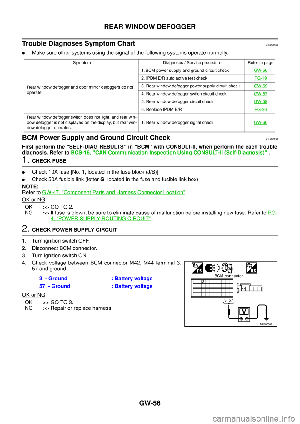
2.CHECK POWER SUPPLY CIRCUIT
1. Turn ignition switch OFF.
2. Disconnect BCM connector.
3. Turn ignition switch ON.
4. Check voltage between BCM connector M42, M44 terminal 3,
57 and ground.
OK or NG
OK >> GO TO 3.
NG >> Repair or replace harness.
Symptom Diagnoses / Service procedure Refer to page
Rear window defogger and door mirror defoggers do not
operate.1. BCM power supply and ground circuit checkGW-56
2. IPDM E/R auto active test checkPG-19
3. Rear window defogger power supply circuit checkGW-59
4. Rear window defogger switch circuit checkGW-57
5. Rear window defogger circuit checkGW-59
6. Replace IPDM E/RPG-26
Rear window defogger switch does not light, and rear win-
dow defogger is not displayed on the display, but rear win-
dow defogger operates.1. Rear window defogger signal checkGW-60
3 - Ground : Battery voltage
57 - Ground : Battery voltage
MIIB0730E
Page 2088 of 3171
HEADLAMP -CONVENTIONAL TYPE-
LT-5
C
D
E
F
G
H
I
J
L
MA
B
LT
HEADLAMP -CONVENTIONAL TYPE-PFP:26010
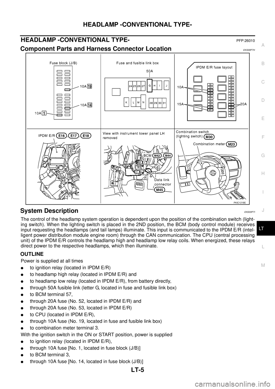
Component Parts and Harness Connector LocationEKS00P7H
System DescriptionEKS00P7I
The control of the headlamp system operation is dependent upon the position of the combination switch (light-
ing switch). When the lighting switch is placed in the 2ND position, the BCM (body control module) receives
input requesting the headlamps (and tail lamps) illuminate. This input is communicated to the IPDM E/R (intel-
ligent power distribution module engine room) through the CAN communication. The CPU (central processing
unit) of the IPDM E/R controls the headlamp high and headlamp low relay coils. When energized, these relays
direct power to the respective headlamps, which then illuminate.
OUTLINE
Power is supplied at all times
lto ignition relay (located in IPDM E/R)
lto headlamp high relay (located in IPDM E/R) and
lto headlamp low relay (located in IPDM E/R), from battery directly,
lthrough 50A fusible link (letter G, located in fuse and fusible link box)
lto BCM terminal 57,
lthrough 20A fuse (No. 52, located in IPDM E/R) and
lthrough 20A fuse (No. 53, located in IPDM E/R)
lto CPU (located in IPDM E/R),
lthrough 10A fuse (No. 19, located in fuse and fusible link box)
lto combination meter terminal 3.
With the ignition switch in the ON or START position, power is supplied
lto ignition relay (located in IPDM E/R),
lthrough 10A fuse [No. 1, located in fuse block (J/B)]
lto BCM terminal 3,
lthrough 10A fuse [No. 14, located in fuse block (J/B)]
PKIC1218E
Page 2154 of 3171
FRONT FOG LAMP
LT-71
C
D
E
F
G
H
I
J
L
MA
B
LT
FRONT FOG LAMPPFP:26150
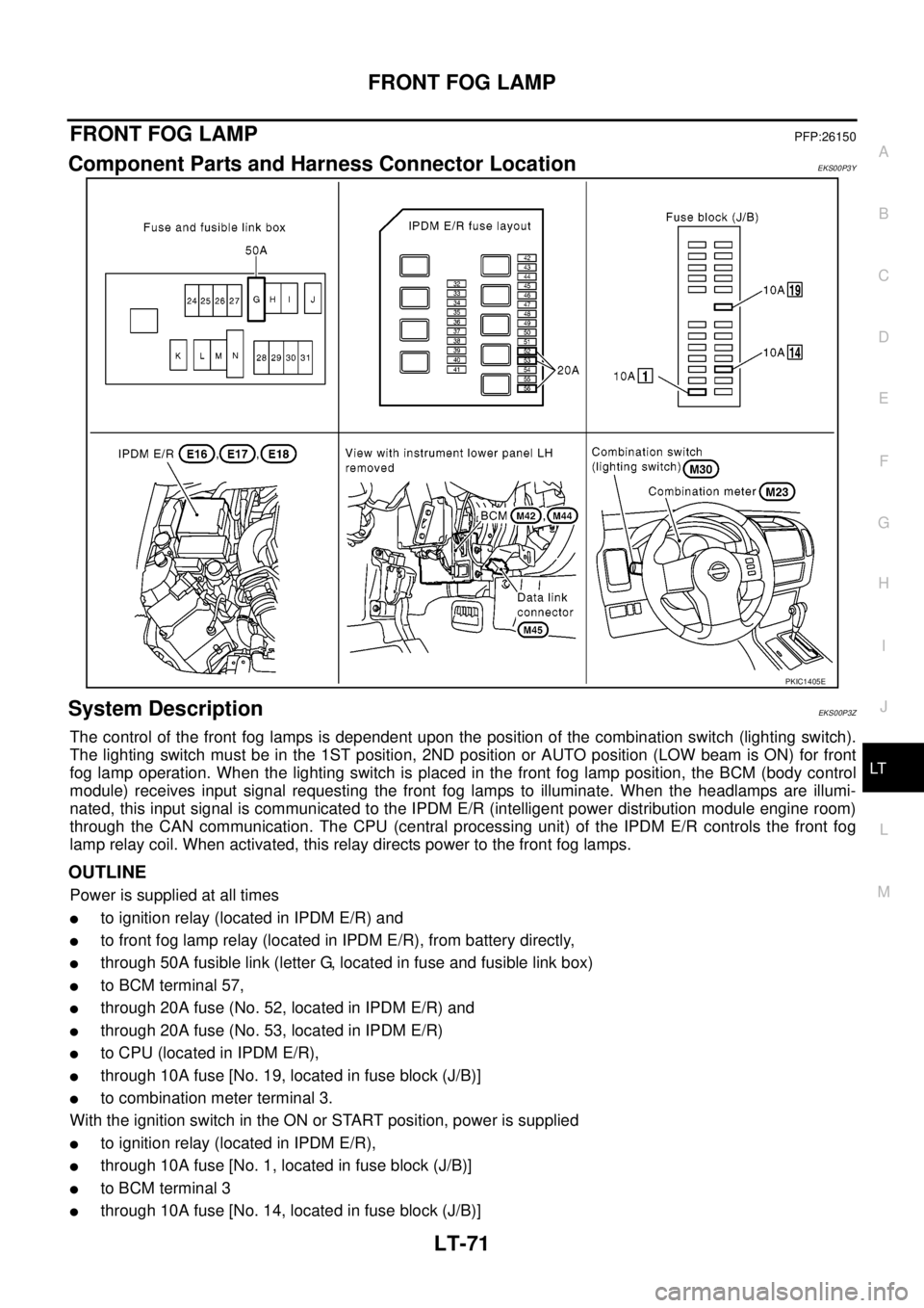
Component Parts and Harness Connector LocationEKS00P3Y
System DescriptionEKS00P3Z
The control of the front fog lamps is dependent upon the position of the combination switch (lighting switch).
The lighting switch must be in the 1ST position, 2ND position or AUTO position (LOW beam is ON) for front
fog lamp operation. When the lighting switch is placed in the front fog lamp position, the BCM (body control
module) receives input signal requesting the front fog lamps to illuminate. When the headlamps are illumi-
nated, this input signal is communicated to the IPDM E/R (intelligent power distribution module engine room)
through the CAN communication. The CPU (central processing unit) of the IPDM E/R controls the front fog
lamp relay coil. When activated, this relay directs power to the front fog lamps.
OUTLINE
Power is supplied at all times
lto ignition relay (located in IPDM E/R) and
lto front fog lamp relay (located in IPDM E/R), from battery directly,
lthrough 50A fusible link (letter G, located in fuse and fusible link box)
lto BCM terminal 57,
lthrough 20A fuse (No. 52, located in IPDM E/R) and
lthrough 20A fuse (No. 53, located in IPDM E/R)
lto CPU (located in IPDM E/R),
lthrough 10A fuse [No. 19, located in fuse block (J/B)]
lto combination meter terminal 3.
With the ignition switch in the ON or START position, power is supplied
lto ignition relay (located in IPDM E/R),
lthrough 10A fuse [No. 1, located in fuse block (J/B)]
lto BCM terminal 3
lthrough 10A fuse [No. 14, located in fuse block (J/B)]
PKIC1405E
Page 2170 of 3171
REAR FOG LAMP
LT-87
C
D
E
F
G
H
I
J
L
MA
B
LT
REAR FOG LAMPPFP:26550
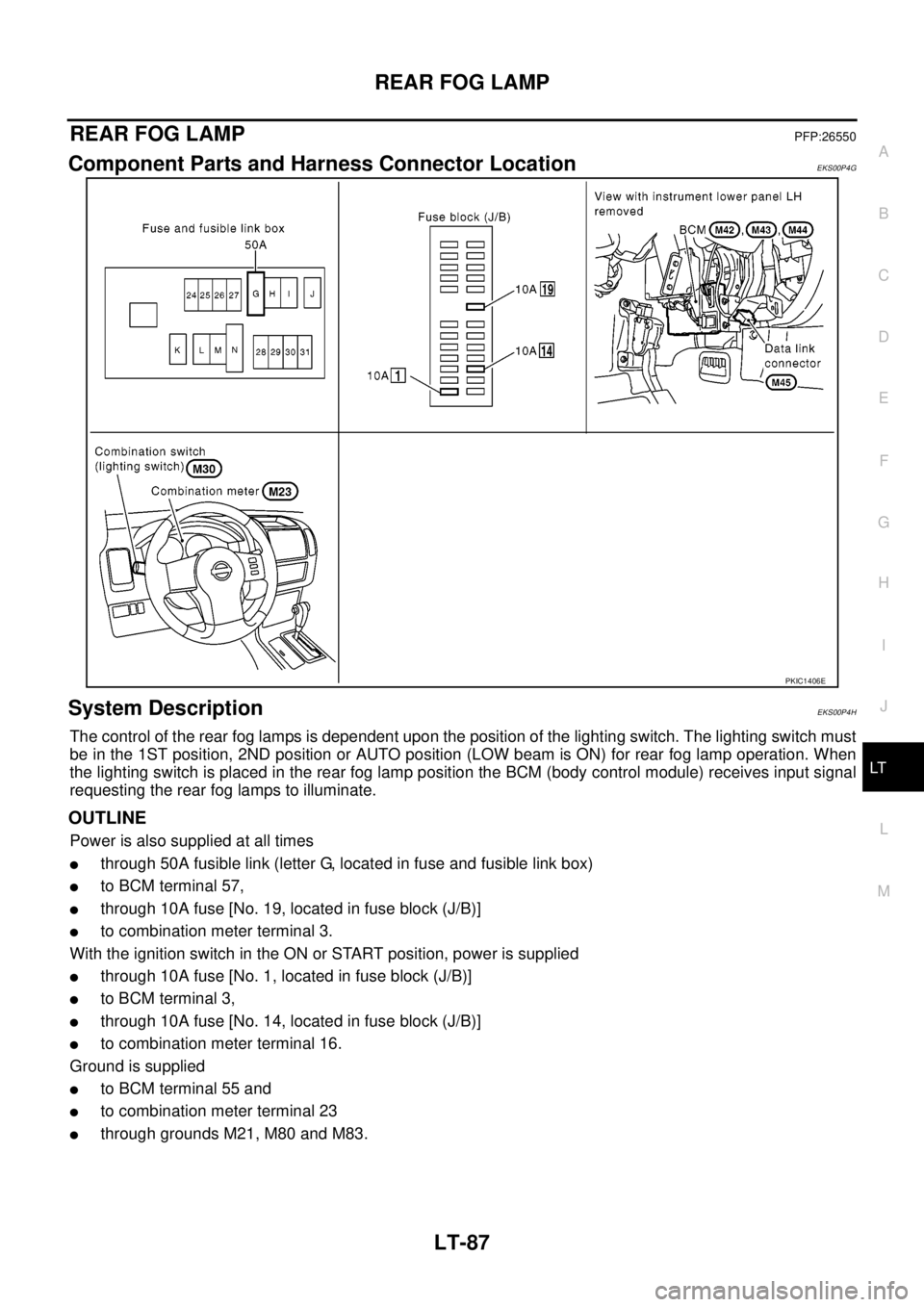
Component Parts and Harness Connector LocationEKS00P4G
System DescriptionEKS00P4H
The control of the rear fog lamps is dependent upon the position of the lighting switch. The lighting switch must
be in the 1ST position, 2ND position or AUTO position (LOW beam is ON) for rear fog lamp operation. When
the lighting switch is placed in the rear fog lamp position the BCM (body control module) receives input signal
requesting the rear fog lamps to illuminate.
OUTLINE
Power is also supplied at all times
lthrough 50A fusible link (letter G, located in fuse and fusible link box)
lto BCM terminal 57,
lthrough 10A fuse [No. 19, located in fuse block (J/B)]
lto combination meter terminal 3.
With the ignition switch in the ON or START position, power is supplied
lthrough 10A fuse [No. 1, located in fuse block (J/B)]
lto BCM terminal 3,
lthrough 10A fuse [No. 14, located in fuse block (J/B)]
lto combination meter terminal 16.
Ground is supplied
lto BCM terminal 55 and
lto combination meter terminal 23
lthrough grounds M21, M80 and M83.
PKIC1406E
Page 2180 of 3171
TURN SIGNAL AND HAZARD WARNING LAMPS
LT-97
C
D
E
F
G
H
I
J
L
MA
B
LT
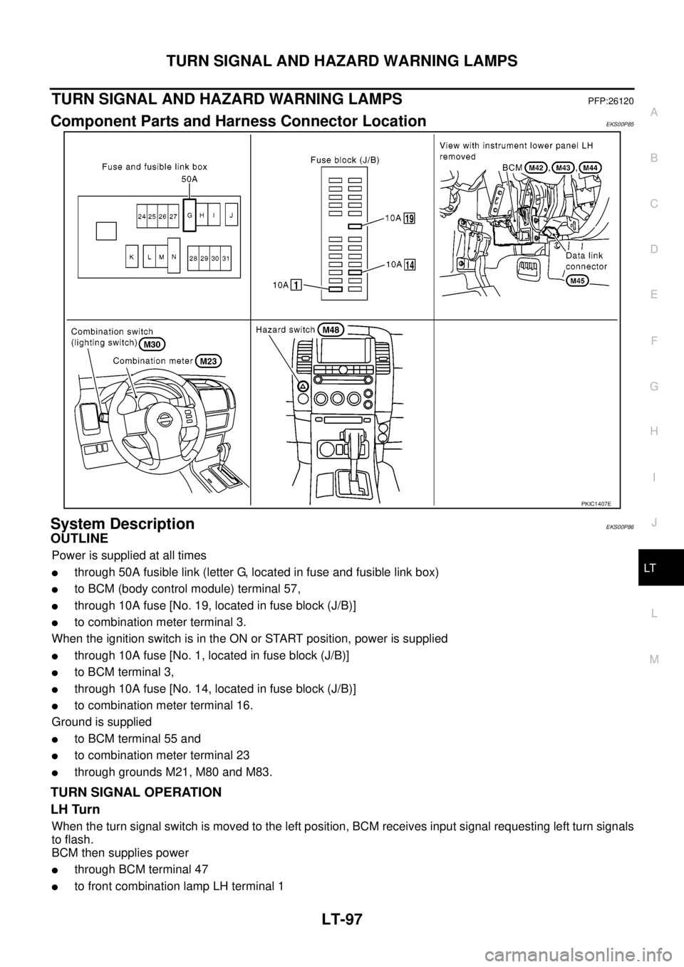
TURN SIGNAL AND HAZARD WARNING LAMPSPFP:26120
Component Parts and Harness Connector LocationEKS00P85
System DescriptionEKS00P86
OUTLINE
Power is supplied at all times
lthrough 50A fusible link (letter G, located in fuse and fusible link box)
lto BCM (body control module) terminal 57,
lthrough 10A fuse [No. 19, located in fuse block (J/B)]
lto combination meter terminal 3.
When the ignition switch is in the ON or START position, power is supplied
lthrough 10A fuse [No. 1, located in fuse block (J/B)]
lto BCM terminal 3,
lthrough 10A fuse [No. 14, located in fuse block (J/B)]
lto combination meter terminal 16.
Ground is supplied
lto BCM terminal 55 and
lto combination meter terminal 23
lthrough grounds M21, M80 and M83.
TURN SIGNAL OPERATION
LH Turn
When the turn signal switch is moved to the left position, BCM receives input signal requesting left turn signals
to flash.
BCM then supplies power
lthrough BCM terminal 47
lto front combination lamp LH terminal 1
PKIC1407E
Page 2208 of 3171
PARKING, LICENSE PLATE AND TAIL LAMPS
LT-125
C
D
E
F
G
H
I
J
L
MA
B
LT
PARKING, LICENSE PLATE AND TAIL LAMPSPFP:26550
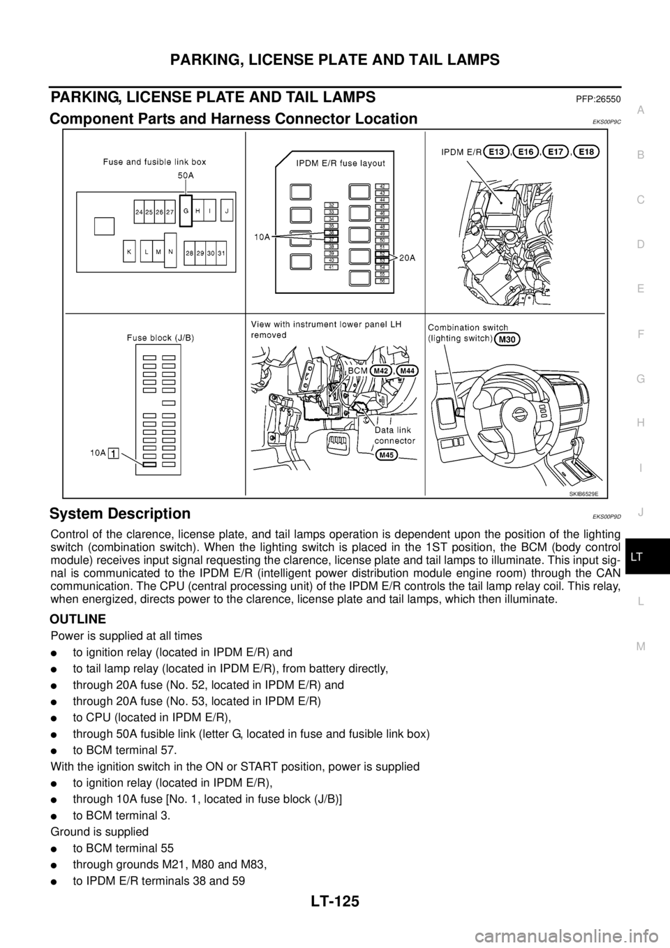
Component Parts and Harness Connector LocationEKS00P9C
System DescriptionEKS00P9D
Control of the clarence, license plate, and tail lamps operation is dependent upon the position of the lighting
switch (combination switch). When the lighting switch is placed in the 1ST position, the BCM (body control
module) receives input signal requesting the clarence, license plate and tail lamps to illuminate. This input sig-
nal is communicated to the IPDM E/R (intelligent power distribution module engine room) through the CAN
communication. The CPU (central processing unit) of the IPDM E/R controls the tail lamp relay coil. This relay,
when energized, directs power to the clarence, license plate and tail lamps, which then illuminate.
OUTLINE
Power is supplied at all times
lto ignition relay (located in IPDM E/R) and
lto tail lamp relay (located in IPDM E/R), from battery directly,
lthrough 20A fuse (No. 52, located in IPDM E/R) and
lthrough 20A fuse (No. 53, located in IPDM E/R)
lto CPU (located in IPDM E/R),
lthrough 50A fusible link (letter G, located in fuse and fusible link box)
lto BCM terminal 57.
With the ignition switch in the ON or START position, power is supplied
lto ignition relay (located in IPDM E/R),
lthrough 10A fuse [No. 1, located in fuse block (J/B)]
lto BCM terminal 3.
Ground is supplied
lto BCM terminal 55
lthrough grounds M21, M80 and M83,
lto IPDM E/R terminals 38 and 59
SKIB6529E