2005 NISSAN NAVARA relay
[x] Cancel search: relayPage 3046 of 3171
TROUBLE DIAGNOSIS FOR SYSTEM
TF-79
C
E
F
G
H
I
J
K
L
MA
B
TF
DIAGNOSTIC PROCEDURE
1.CHECK POWER SUPPLY
1. Turn ignition switch “OFF”. (Stay for at least 5 seconds.)
2. Disconnect transfer control unit harness connector.
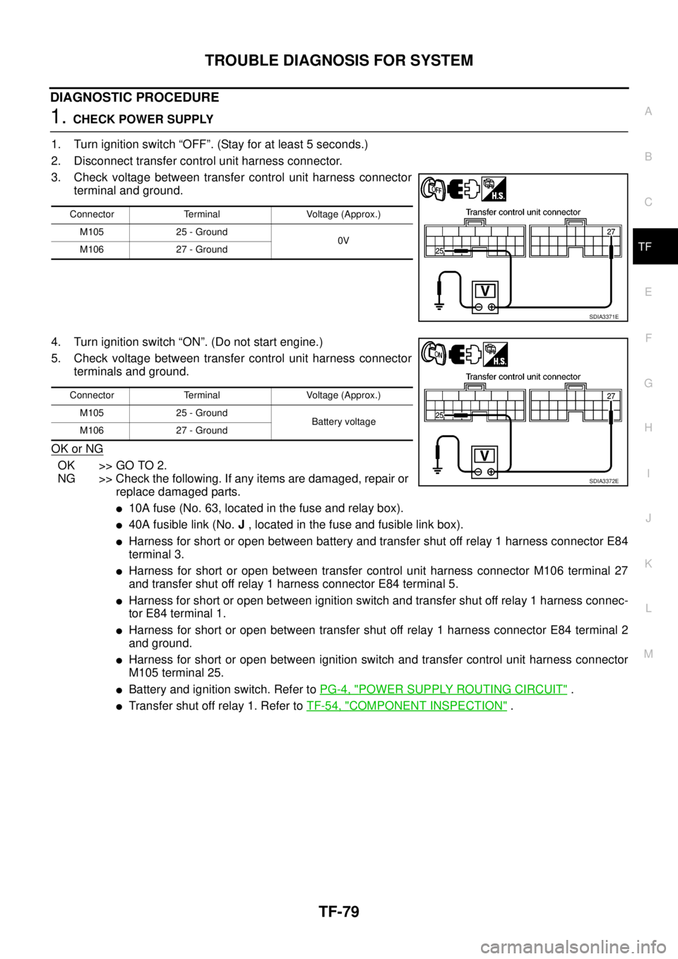
3. Check voltage between transfer control unit harness connector
terminal and ground.
4. Turn ignition switch “ON”. (Do not start engine.)
5. Check voltage between transfer control unit harness connector
terminals and ground.
OK or NG
OK >> GO TO 2.
NG >> Check the following. If any items are damaged, repair or
replace damaged parts.
l10A fuse (No. 63, located in the fuse and relay box).
l40A fusible link (No.J, located in the fuse and fusible link box).
lHarness for short or open between battery and transfer shut off relay 1 harness connector E84
terminal 3.
lHarness for short or open between transfer control unit harness connector M106 terminal 27
and transfer shut off relay 1 harness connector E84 terminal 5.
lHarness for short or open between ignition switch and transfer shut off relay 1 harness connec-
tor E84 terminal 1.
lHarness for short or open between transfer shut off relay 1 harness connector E84 terminal 2
and ground.
lHarness for short or open between ignition switch and transfer control unit harness connector
M105 terminal 25.
lBattery and ignition switch. Refer toPG-4, "POWER SUPPLY ROUTING CIRCUIT".
lTransfer shut off relay 1. Refer toTF-54, "COMPONENT INSPECTION".
Connector Terminal Voltage (Approx.)
M105 25 - Ground
0V
M106 27 - Ground
SDIA3371E
Connector Terminal Voltage (Approx.)
M105 25 - Ground
Battery voltage
M106 27 - Ground
SDIA3372E
Page 3047 of 3171
TF-80
TROUBLE DIAGNOSIS FOR SYSTEM
2.CHECK GROUND CIRCUIT
1. Turn ignition switch "OFF". (Stay for at least 5 seconds.)
2. Disconnect transfer control unit harness connector.
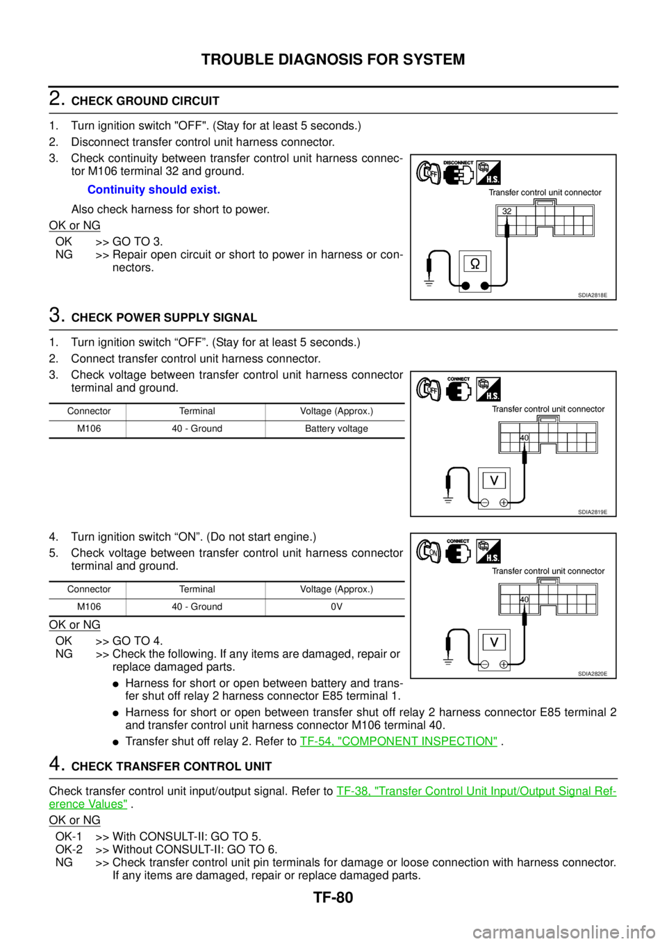
3. Check continuity between transfer control unit harness connec-
tor M106 terminal 32 and ground.
Also check harness for short to power.
OK or NG
OK >> GO TO 3.
NG >> Repair open circuit or short to power in harness or con-
nectors.
3.CHECK POWER SUPPLY SIGNAL
1. Turn ignition switch “OFF”. (Stay for at least 5 seconds.)
2. Connect transfer control unit harness connector.
3. Check voltage between transfer control unit harness connector
terminal and ground.
4. Turn ignition switch “ON”. (Do not start engine.)
5. Check voltage between transfer control unit harness connector
terminal and ground.
OK or NG
OK >> GO TO 4.
NG >> Check the following. If any items are damaged, repair or
replace damaged parts.
lHarness for short or open between battery and trans-
fer shut off relay 2 harness connector E85 terminal 1.
lHarness for short or open between transfer shut off relay 2 harness connector E85 terminal 2
and transfer control unit harness connector M106 terminal 40.
lTransfer shut off relay 2. Refer toTF-54, "COMPONENT INSPECTION".
4.CHECK TRANSFER CONTROL UNIT
Check transfer control unit input/output signal. Refer toTF-38, "
Transfer Control Unit Input/Output Signal Ref-
erence Values".
OK or NG
OK-1 >> With CONSULT-II: GO TO 5.
OK-2 >> Without CONSULT-II: GO TO 6.
NG >> Check transfer control unit pin terminals for damage or loose connection with harness connector.
If any items are damaged, repair or replace damaged parts. Continuity should exist.
SDIA2818E
Connector Terminal Voltage (Approx.)
M106 40 - Ground Battery voltage
SDIA2819E
Connector Terminal Voltage (Approx.)
M106 40 - Ground 0V
SDIA2820E
Page 3056 of 3171
TROUBLE DIAGNOSIS FOR SYMPTOMS
TF-89
C
E
F
G
H
I
J
K
L
MA
B
TF
DIAGNOSTIC PROCEDURE
1.CHECK TRANSFER CONTROL UNIT POWER SUPPLY CIRCUIT
1. Turn ignition switch “OFF”. (Stay for at least 5 seconds.)
2. Disconnect transfer control unit harness connector.
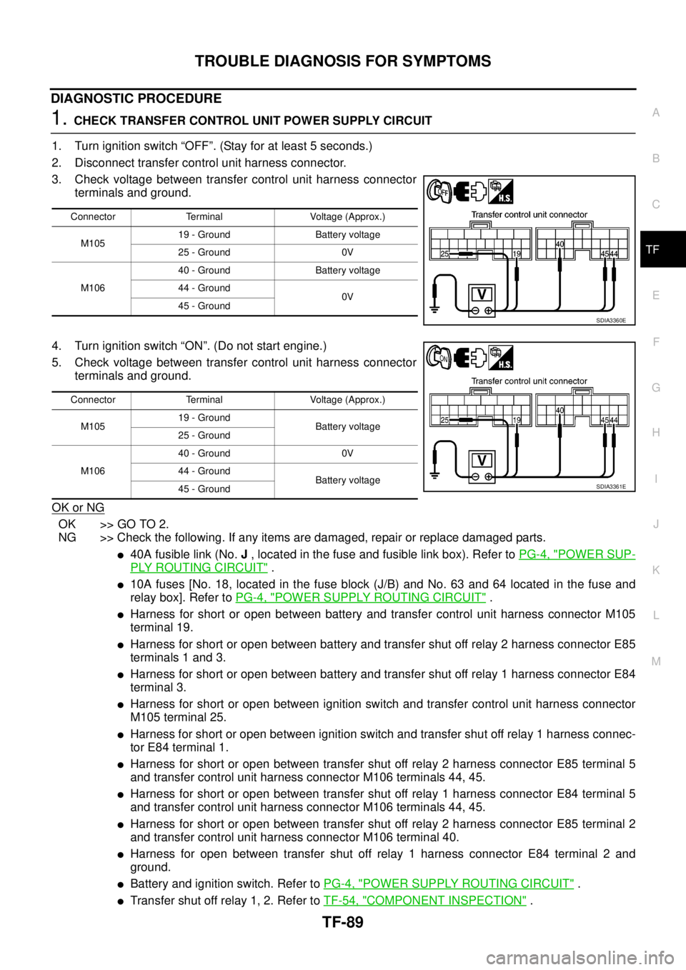
3. Check voltage between transfer control unit harness connector
terminals and ground.
4. Turn ignition switch “ON”. (Do not start engine.)
5. Check voltage between transfer control unit harness connector
terminals and ground.
OK or NG
OK >> GO TO 2.
NG >> Check the following. If any items are damaged, repair or replace damaged parts.
l40A fusible link (No.J, located in the fuse and fusible link box). Refer toPG-4, "POWER SUP-
PLY ROUTING CIRCUIT".
l10A fuses [No. 18, located in the fuse block (J/B) and No. 63 and 64 located in the fuse and
relay box]. Refer toPG-4, "
POWER SUPPLY ROUTING CIRCUIT".
lHarness for short or open between battery and transfer control unit harness connector M105
terminal 19.
lHarness for short or open between battery and transfer shut off relay 2 harness connector E85
terminals 1 and 3.
lHarness for short or open between battery and transfer shut off relay 1 harness connector E84
terminal 3.
lHarness for short or open between ignition switch and transfer control unit harness connector
M105 terminal 25.
lHarness for short or open between ignition switch and transfer shut off relay 1 harness connec-
tor E84 terminal 1.
lHarness for short or open between transfer shut off relay 2 harness connector E85 terminal 5
and transfer control unit harness connector M106 terminals 44, 45.
lHarness for short or open between transfer shut off relay 1 harness connector E84 terminal 5
and transfer control unit harness connector M106 terminals 44, 45.
lHarness for short or open between transfer shut off relay 2 harness connector E85 terminal 2
and transfer control unit harness connector M106 terminal 40.
lHarness for open between transfer shut off relay 1 harness connector E84 terminal 2 and
ground.
lBattery and ignition switch. Refer toPG-4, "POWER SUPPLY ROUTING CIRCUIT".
lTransfer shut off relay 1, 2. Refer toTF-54, "COMPONENT INSPECTION".
Connector Terminal Voltage (Approx.)
M10519 - Ground Battery voltage
25 - Ground 0V
M10640 - Ground Battery voltage
44 - Ground
0V
45 - Ground
SDIA3360E
Connector Terminal Voltage (Approx.)
M10519 - Ground
Battery voltage
25 - Ground
M10640 - Ground 0V
44 - Ground
Battery voltage
45 - Ground
SDIA3361E
Page 3057 of 3171
TF-90
TROUBLE DIAGNOSIS FOR SYMPTOMS
2.CHECK TRANSFER CONTROL UNIT GROUND CIRCUIT
1. Turn ignition switch “OFF”. (Stay for at least 5 seconds.)
2. Disconnect transfer control unit harness connectors.
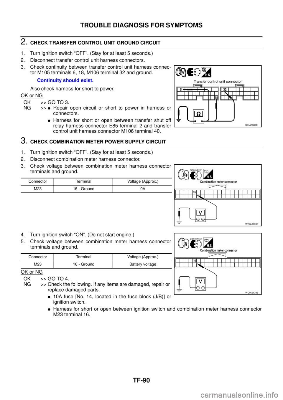
3. Check continuity between transfer control unit harness connec-
tor M105 terminals 6, 18, M106 terminal 32 and ground.
Also check harness for short to power.
OK or NG
OK >> GO TO 3.
NG >>
lRepair open circuit or short to power in harness or
connectors.
lHarness for short or open between transfer shut off
relay harness connector E85 terminal 2 and transfer
control unit harness connector M106 terminal 40.
3.CHECK COMBINATION METER POWER SUPPLY CIRCUIT
1. Turn ignition switch “OFF”. (Stay for at least 5 seconds.)
2. Disconnect combination meter harness connector.
3. Check voltage between combination meter harness connector
terminals and ground.
4. Turn ignition switch “ON”. (Do not start engine.)
5. Check voltage between combination meter harness connector
terminals and ground.
OK or NG
OK >> GO TO 4.
NG >> Check the following. If any items are damaged, repair or
replace damaged parts.
l10A fuse [No. 14, located in the fuse block (J/B)] or
ignition switch.
lHarness for short or open between ignition switch and combination meter harness connector
M23 terminal 16. Continuity should exist.
SDIA3362E
Connector Terminal Voltage (Approx.)
M23 16 - Ground 0V
WDIA0178E
Connector Terminal Voltage (Approx.)
M23 16 - Ground Battery voltage
WDIA0179E
Page 3059 of 3171
TF-92
TROUBLE DIAGNOSIS FOR SYMPTOMS
DIAGNOSTIC PROCEDURE
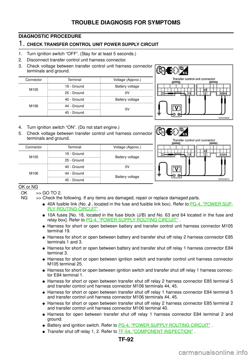
1.CHECK TRANSFER CONTROL UNIT POWER SUPPLY CIRCUIT
1. Turn ignition switch “OFF”. (Stay for at least 5 seconds.)
2. Disconnect transfer control unit harness connector.
3. Check voltage between transfer control unit harness connector
terminals and ground.
4. Turn ignition switch “ON”. (Do not start engine.)
5. Check voltage between transfer control unit harness connector
terminals and ground.
OK or NG
OK >> GO TO 2.
NG >> Check the following. If any items are damaged, repair or replace damaged parts.
l40A fusible link (No.J, located in the fuse and fusible link box). Refer toPG-4, "POWER SUP-
PLY ROUTING CIRCUIT".
l10A fuses [No. 18, located in the fuse block (J/B) and No. 63 and 64 located in the fuse and
relay box]. Refer toPG-4, "
POWER SUPPLY ROUTING CIRCUIT".
lHarness for short or open between battery and transfer control unit harness connector M105
terminal 19.
lHarness for short or open between battery and transfer shut off relay 2 harness connector E85
terminals 1 and 3.
lHarness for short or open between battery and transfer shut off relay 1 harness connector E84
terminal 3.
lHarness for short or open between ignition switch and transfer control unit harness connector
M105 terminal 25.
lHarness for short or open between ignition switch and transfer shut off relay 1 harness connec-
tor E84 terminal 1.
lHarness for short or open between transfer shut off relay 2 harness connector E85 terminal 5
and transfer control unit harness connector M106 terminals 44, 45.
lHarness for short or open between transfer shut off relay 1 harness connector E84 terminal 5
and transfer control unit harness connector M106 terminals 44, 45.
lHarness for short or open between transfer shut off relay 2 harness connector E85 terminal 2
and transfer control unit harness connector M106 terminal 40.
lHarness for open between transfer shut off relay 1 harness connector E84 terminal 2 and
ground.
lBattery and ignition switch. Refer toPG-4, "POWER SUPPLY ROUTING CIRCUIT".
lTransfer shut off relay 1, 2. Refer toTF-54, "COMPONENT INSPECTION".
Connector Terminal Voltage (Approx.)
M10519 - Ground Battery voltage
25 - Ground 0V
M10640 - Ground Battery voltage
44 - Ground
0V
45 - Ground
SDIA3360E
Connector Terminal Voltage (Approx.)
M10519 - Ground
Battery voltage
25 - Ground
M10640 - Ground 0V
44 - Ground
Battery voltage
45 - Ground
SDIA3361E
Page 3060 of 3171
TROUBLE DIAGNOSIS FOR SYMPTOMS
TF-93
C
E
F
G
H
I
J
K
L
MA
B
TF
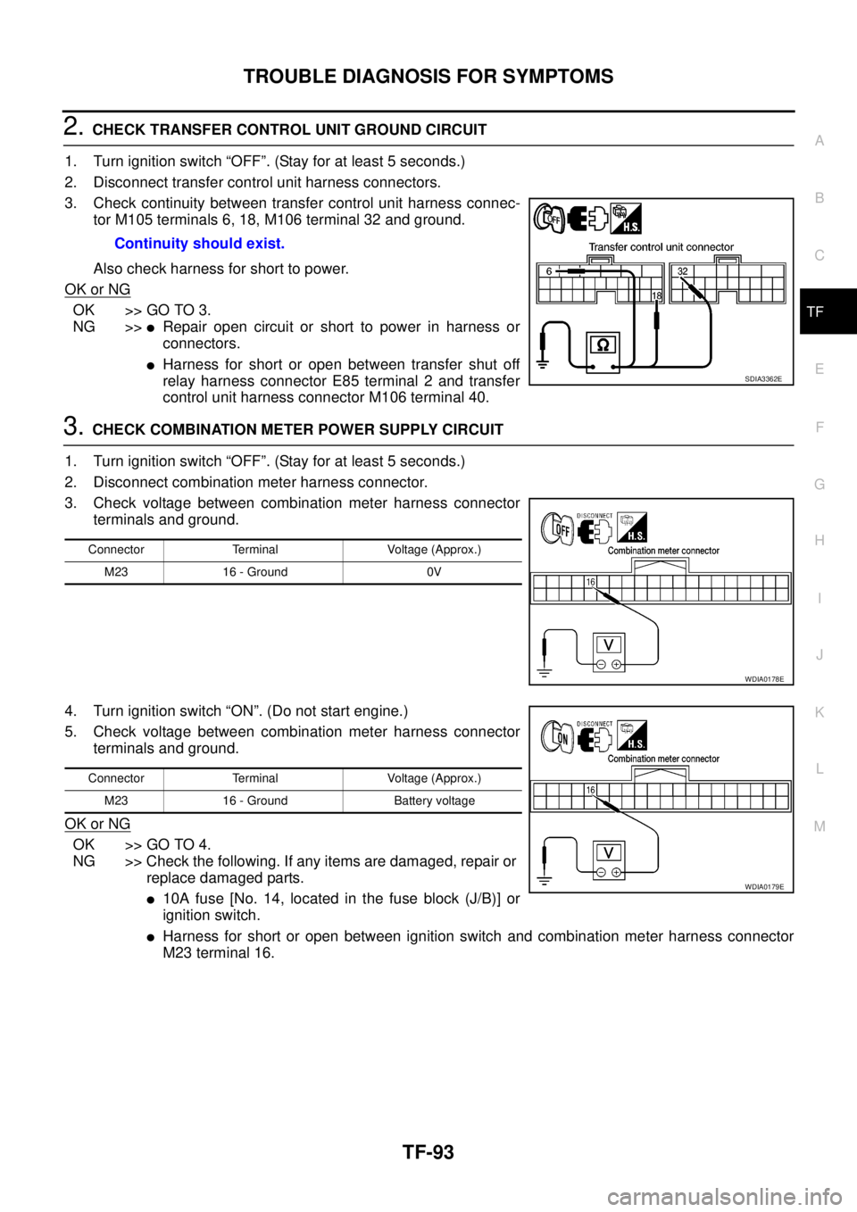
2.CHECK TRANSFER CONTROL UNIT GROUND CIRCUIT
1. Turn ignition switch “OFF”. (Stay for at least 5 seconds.)
2. Disconnect transfer control unit harness connectors.
3. Check continuity between transfer control unit harness connec-
tor M105 terminals 6, 18, M106 terminal 32 and ground.
Also check harness for short to power.
OK or NG
OK >> GO TO 3.
NG >>
lRepair open circuit or short to power in harness or
connectors.
lHarness for short or open between transfer shut off
relay harness connector E85 terminal 2 and transfer
control unit harness connector M106 terminal 40.
3.CHECK COMBINATION METER POWER SUPPLY CIRCUIT
1. Turn ignition switch “OFF”. (Stay for at least 5 seconds.)
2. Disconnect combination meter harness connector.
3. Check voltage between combination meter harness connector
terminals and ground.
4. Turn ignition switch “ON”. (Do not start engine.)
5. Check voltage between combination meter harness connector
terminals and ground.
OK or NG
OK >> GO TO 4.
NG >> Check the following. If any items are damaged, repair or
replace damaged parts.
l10A fuse [No. 14, located in the fuse block (J/B)] or
ignition switch.
lHarness for short or open between ignition switch and combination meter harness connector
M23 terminal 16. Continuity should exist.
SDIA3362E
Connector Terminal Voltage (Approx.)
M23 16 - Ground 0V
WDIA0178E
Connector Terminal Voltage (Approx.)
M23 16 - Ground Battery voltage
WDIA0179E
Page 3115 of 3171
WW-4
FRONT WIPER AND WASHER SYSTEM
FRONT WIPER AND WASHER SYSTEM
PFP:28810
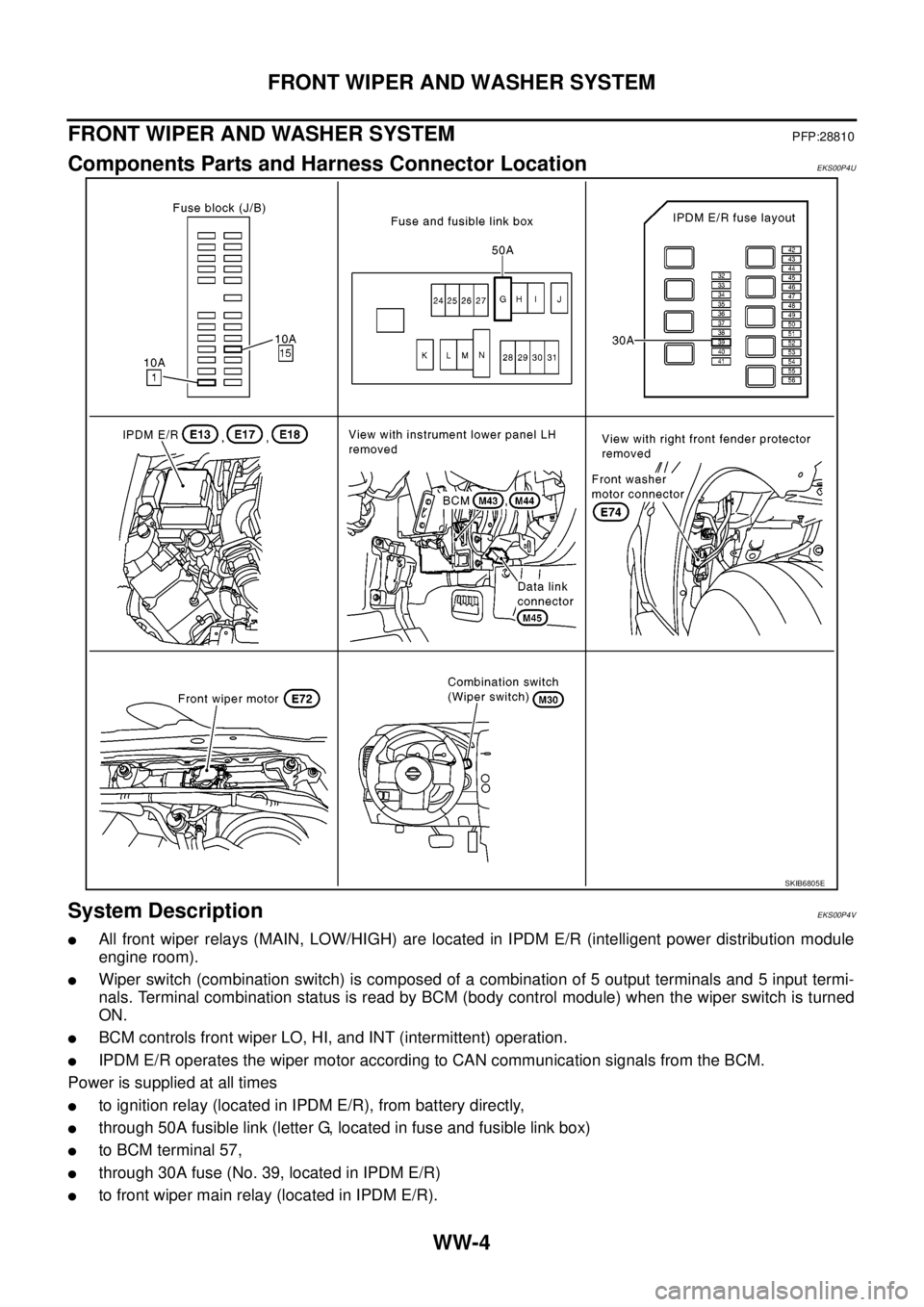
Components Parts and Harness Connector LocationEKS00P4U
System DescriptionEKS00P4V
lAll front wiper relays (MAIN, LOW/HIGH) are located in IPDM E/R (intelligent power distribution module
engine room).
lWiper switch (combination switch) is composed of a combination of 5 output terminals and 5 input termi-
nals. Terminal combination status is read by BCM (body control module) when the wiper switch is turned
ON.
lBCM controls front wiper LO, HI, and INT (intermittent) operation.
lIPDM E/R operates the wiper motor according to CAN communication signals from the BCM.
Power is supplied at all times
lto ignition relay (located in IPDM E/R), from battery directly,
lthrough 50A fusible link (letter G, located in fuse and fusible link box)
lto BCM terminal 57,
lthrough 30A fuse (No. 39, located in IPDM E/R)
lto front wiper main relay (located in IPDM E/R).
SKIB6805E
Page 3116 of 3171
![NISSAN NAVARA 2005 Repair Workshop Manual FRONT WIPER AND WASHER SYSTEM
WW-5
C
D
E
F
G
H
I
J
L
MA
B
WW
With the ignition switch in ON or START position, power is supplied
lthrough 10A fuse [No. 15, located in fuse block (J/B)]
lto combination NISSAN NAVARA 2005 Repair Workshop Manual FRONT WIPER AND WASHER SYSTEM
WW-5
C
D
E
F
G
H
I
J
L
MA
B
WW
With the ignition switch in ON or START position, power is supplied
lthrough 10A fuse [No. 15, located in fuse block (J/B)]
lto combination](/manual-img/5/57362/w960_57362-3115.png)
FRONT WIPER AND WASHER SYSTEM
WW-5
C
D
E
F
G
H
I
J
L
MA
B
WW
With the ignition switch in ON or START position, power is supplied
lthrough 10A fuse [No. 15, located in fuse block (J/B)]
lto combination switch terminal 2,
lthrough 10A fuse [No. 1, located in fuse block (J/B)]
lto BCM terminal 3.
Ground is supplied
lto BCM terminal 55 and
lto combination switch terminal 9
lthrough grounds M21, M80 and M83,
lto IPDM E/R terminals 38 and 59 and
lto front wiper motor terminal 2
lthrough grounds E21, E41 and E61.
LOW SPEED WIPER OPERATION
When the ignition switch is in the ON or START position, and the front wiper switch is turned to the low posi-
tion, the BCM detects a low speed wiper ON request through the combination switch (wiper switch) reading
function.
The BCM then sends a front wiper (low) request signal with CAN communication.
lfrom BCM terminals 21 and 22
lto IPDM E/R terminals 39 and 40.
When IPDM E/R receives front wiper (low) request signal, it supplies ground to energize the front wiper main
relay.
With the front wiper LOW/ HIGH relay energized, power is supplied
lthrough front wiper main relay
lthrough front wiper LOW/HIGH relay
lthrough IPDM E/R terminal 32
lto front wiper motor terminal 1.
Ground is supplied
lto front wiper motor terminal 2
lthrough grounds E21, E41 and E61.
With power and ground supplied, the front wiper motor operates at low speed.
HI SPEED WIPER OPERATION
When the ignition switch is in the ON or START position, and the front wiper switch is turned to the high posi-
tion, the BCM detects a high speed wiper ON request through the combination switch (wiper switch) reading
function.
The BCM then sends a front wiper (high) request signal with CAN communication.
lfrom BCM terminals 21 and 22
lto IPDM E/R terminals 39 and 40.
When IPDM E/R receives front wiper (high) request signal, it supplies ground to energize the front wiper main
relays.
With the front wiper LOW/HIGH relays energized, power is supplied
lthrough front wiper main relay
lthrough front wiper LOW/HIGH relay
lthrough IPDM E/R terminal 35
lto front wiper motor terminal 4.
Ground is supplied
lto front wiper motor terminal 2
lthrough grounds E21, E41 and E61.
With power and ground supplied, the front wiper motor operates at high speed.