2005 NISSAN NAVARA check transmission fluid
[x] Cancel search: check transmission fluidPage 201 of 3171
TROUBLE DIAGNOSIS FOR SYMPTOMS
AT-193
D
E
F
G
H
I
J
K
L
MA
B
AT
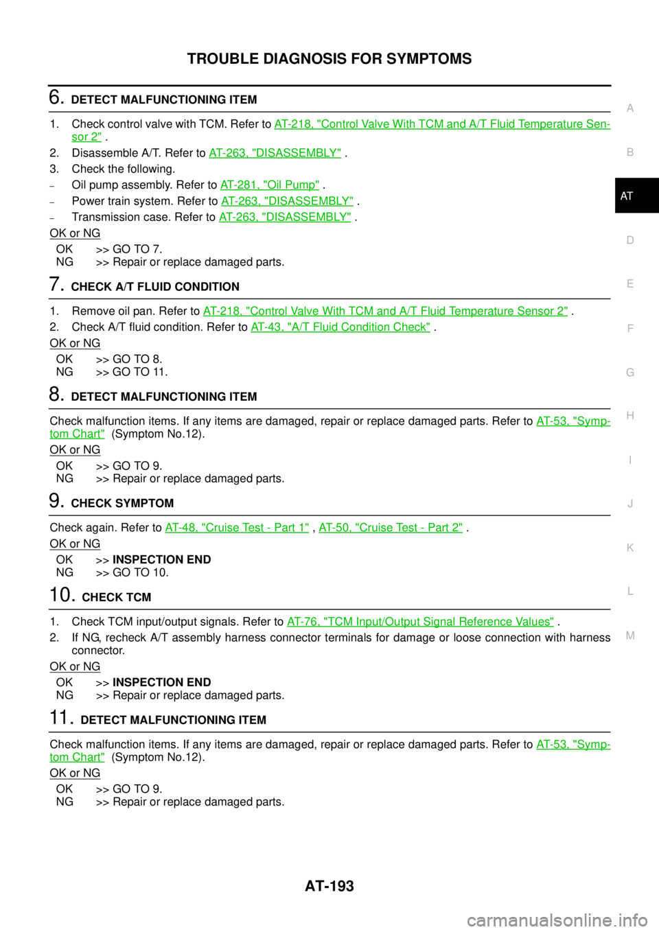
6.DETECT MALFUNCTIONING ITEM
1. Check control valve with TCM. Refer toAT- 2 1 8 , "
Control Valve With TCM and A/T Fluid Temperature Sen-
sor 2".
2. Disassemble A/T. Refer toAT- 2 6 3 , "
DISASSEMBLY".
3. Check the following.
–Oil pump assembly. Refer toAT- 2 8 1 , "Oil Pump".
–Power train system. Refer toAT- 2 6 3 , "DISASSEMBLY".
–Transmission case. Refer toAT- 2 6 3 , "DISASSEMBLY".
OK or NG
OK >> GO TO 7.
NG >> Repair or replace damaged parts.
7.CHECK A/T FLUID CONDITION
1. Remove oil pan. Refer toAT- 2 1 8 , "
Control Valve With TCM and A/T Fluid Temperature Sensor 2".
2. Check A/T fluid condition. Refer toAT-43, "
A/T Fluid Condition Check".
OK or NG
OK >> GO TO 8.
NG >> GO TO 11.
8.DETECT MALFUNCTIONING ITEM
Check malfunction items. If any items are damaged, repair or replace damaged parts. Refer toAT-53, "
Symp-
tom Chart"(Symptom No.12).
OK or NG
OK >> GO TO 9.
NG >> Repair or replace damaged parts.
9.CHECK SYMPTOM
Check again. Refer toAT-48, "
Cruise Test - Part 1",AT-50, "Cruise Test - Part 2".
OK or NG
OK >>INSPECTION END
NG >> GO TO 10.
10.CHECK TCM
1. Check TCM input/output signals. Refer toAT-76, "
TCM Input/Output Signal Reference Values".
2. If NG, recheck A/T assembly harness connector terminals for damage or loose connection with harness
connector.
OK or NG
OK >>INSPECTION END
NG >> Repair or replace damaged parts.
11 .DETECT MALFUNCTIONING ITEM
Check malfunction items. If any items are damaged, repair or replace damaged parts. Refer toAT-53, "
Symp-
tom Chart"(Symptom No.12).
OK or NG
OK >> GO TO 9.
NG >> Repair or replace damaged parts.
Page 203 of 3171
TROUBLE DIAGNOSIS FOR SYMPTOMS
AT-195
D
E
F
G
H
I
J
K
L
MA
B
AT
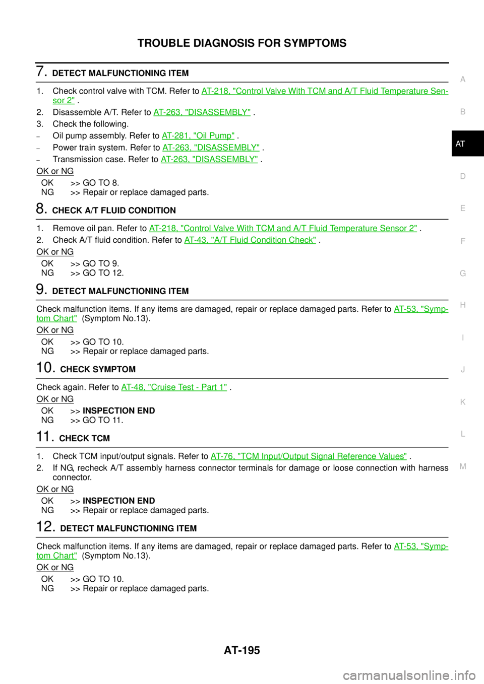
7.DETECT MALFUNCTIONING ITEM
1. Check control valve with TCM. Refer toAT- 2 1 8 , "
Control Valve With TCM and A/T Fluid Temperature Sen-
sor 2".
2. Disassemble A/T. Refer toAT- 2 6 3 , "
DISASSEMBLY".
3. Check the following.
–Oil pump assembly. Refer toAT- 2 8 1 , "Oil Pump".
–Power train system. Refer toAT- 2 6 3 , "DISASSEMBLY".
–Transmission case. Refer toAT- 2 6 3 , "DISASSEMBLY".
OK or NG
OK >> GO TO 8.
NG >> Repair or replace damaged parts.
8.CHECK A/T FLUID CONDITION
1. Remove oil pan. Refer toAT- 2 1 8 , "
Control Valve With TCM and A/T Fluid Temperature Sensor 2".
2. Check A/T fluid condition. Refer toAT-43, "
A/T Fluid Condition Check".
OK or NG
OK >> GO TO 9.
NG >> GO TO 12.
9.DETECT MALFUNCTIONING ITEM
Check malfunction items. If any items are damaged, repair or replace damaged parts. Refer toAT-53, "
Symp-
tom Chart"(Symptom No.13).
OK or NG
OK >> GO TO 10.
NG >> Repair or replace damaged parts.
10.CHECK SYMPTOM
Check again. Refer toAT-48, "
Cruise Test - Part 1".
OK or NG
OK >>INSPECTION END
NG >> GO TO 11.
11 .CHECK TCM
1. Check TCM input/output signals. Refer toAT-76, "
TCM Input/Output Signal Reference Values".
2. If NG, recheck A/T assembly harness connector terminals for damage or loose connection with harness
connector.
OK or NG
OK >>INSPECTION END
NG >> Repair or replace damaged parts.
12.DETECT MALFUNCTIONING ITEM
Check malfunction items. If any items are damaged, repair or replace damaged parts. Refer toAT-53, "
Symp-
tom Chart"(Symptom No.13).
OK or NG
OK >> GO TO 10.
NG >> Repair or replace damaged parts.
Page 204 of 3171
AT-196
TROUBLE DIAGNOSIS FOR SYMPTOMS
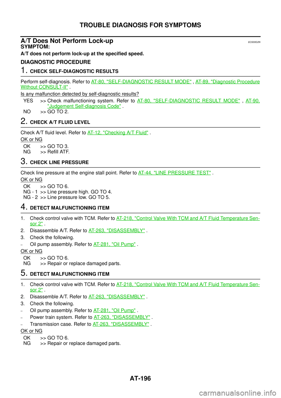
A/T Does Not Perform Lock-up
ECS00G2N
SYMPTOM:
A/T does not perform lock-up at the specified speed.
DIAGNOSTIC PROCEDURE
1.CHECK SELF-DIAGNOSTIC RESULTS
Perform self-diagnosis. Refer toAT-80, "
SELF-DIAGNOSTIC RESULT MODE",AT-89, "Diagnostic Procedure
Without CONSULT-II".
Is any malfunction detected by self-diagnostic results?
YES >> Check malfunctioning system. Refer toAT-80, "SELF-DIAGNOSTIC RESULT MODE",AT- 9 0 ,
"Judgement Self-diagnosis Code".
NO >> GO TO 2.
2.CHECK A/T FLUID LEVEL
Check A/T fluid level. Refer toAT-12, "
Checking A/T Fluid".
OK or NG
OK >> GO TO 3.
NG >> Refill ATF.
3.CHECK LINE PRESSURE
Check line pressure at the engine stall point. Refer toAT-44, "
LINE PRESSURE TEST".
OK or NG
OK >> GO TO 6.
NG - 1 >> Line pressure high. GO TO 4.
NG - 2 >> Line pressure low. GO TO 5.
4.DETECT MALFUNCTIONING ITEM
1. Check control valve with TCM. Refer toAT- 2 1 8 , "
Control Valve With TCM and A/T Fluid Temperature Sen-
sor 2".
2. Disassemble A/T. Refer toAT- 2 6 3 , "
DISASSEMBLY".
3. Check the following.
–Oil pump assembly. Refer toAT- 2 8 1 , "Oil Pump".
OK or NG
OK >> GO TO 6.
NG >> Repair or replace damaged parts.
5.DETECT MALFUNCTIONING ITEM
1. Check control valve with TCM. Refer toAT- 2 1 8 , "
Control Valve With TCM and A/T Fluid Temperature Sen-
sor 2".
2. Disassemble A/T. Refer toAT- 2 6 3 , "
DISASSEMBLY".
3. Check the following.
–Oil pump assembly. Refer toAT- 2 8 1 , "Oil Pump".
–Power train system. Refer toAT- 2 6 3 , "DISASSEMBLY".
–Transmission case. Refer toAT- 2 6 3 , "DISASSEMBLY".
OK or NG
OK >> GO TO 6.
NG >> Repair or replace damaged parts.
Page 249 of 3171
ON-VEHICLE SERVICE
AT-241
D
E
F
G
H
I
J
K
L
MA
B
AT
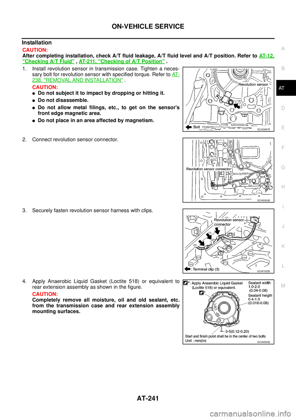
Installation
CAUTION:
After completing installation, check A/T fluid leakage, A/T fluid level and A/T position. Refer toAT- 1 2 ,
"Checking A/T Fluid",AT- 2 11 , "Checking of A/T Position".
1. Install revolution sensor in transmission case. Tighten a neces-
sary bolt for revolution sensor with specified torque. Refer toAT-
238, "REMOVAL AND INSTALLATION".
CAUTION:
lDo not subject it to impact by dropping or hitting it.
lDo not disassemble.
lDo not allow metal filings, etc., to get on the sensor's
front edge magnetic area.
lDo not place in an area affected by magnetism.
2. Connect revolution sensor connector.
3. Securely fasten revolution sensor harness with clips.
4. Apply Anaerobic Liquid Gasket (Loctite 518) or equivalent to
rear extension assembly as shown in the figure.
CAUTION:
Completely remove all moisture, oil and old sealant, etc.
from the transmission case and rear extension assembly
mounting surfaces.
SCIA3997E
SCIA5024E
SCIA7022E
SCIA4934E
Page 258 of 3171
AT-250
TRANSMISSION ASSEMBLY
INSPECTION
Installation and Inspection of Torque Converter
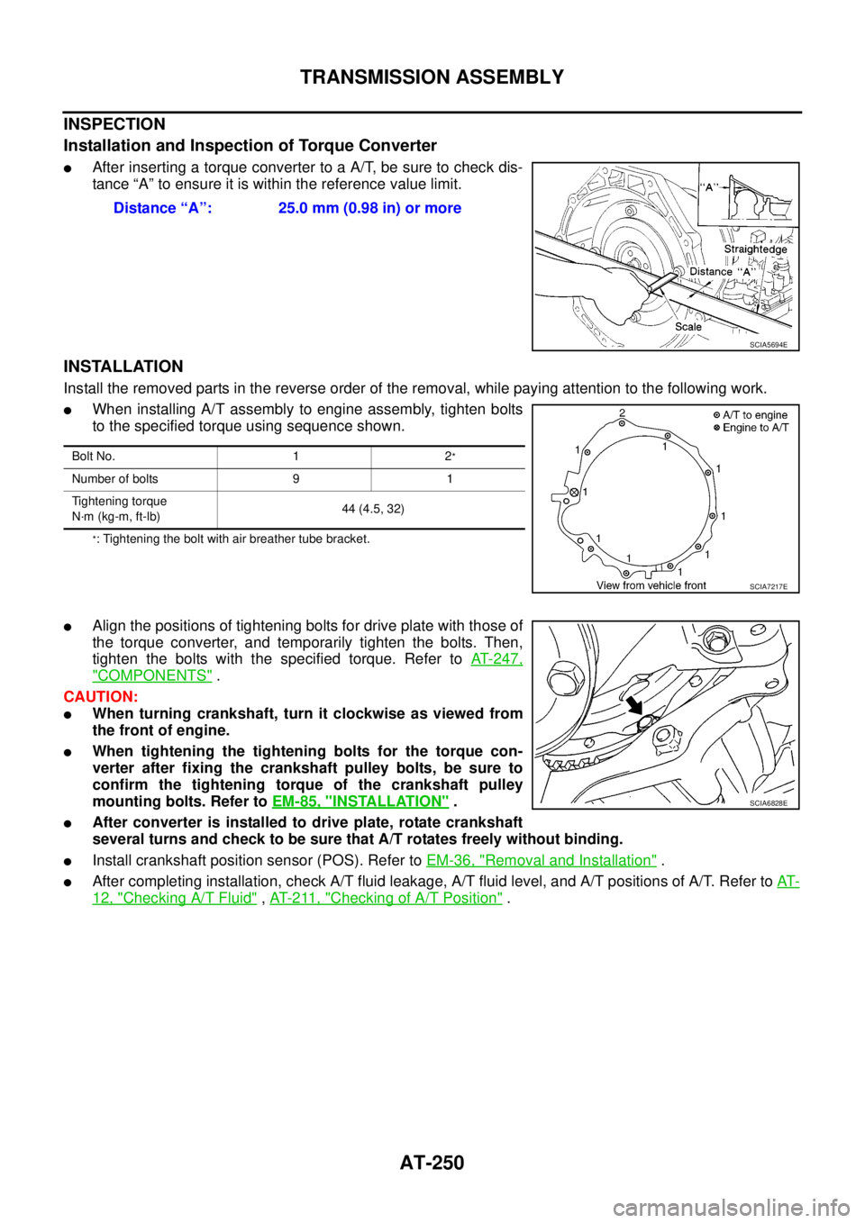
lAfter inserting a torque converter to a A/T, be sure to check dis-
tance “A” to ensure it is within the reference value limit.
INSTALLATION
Install the removed parts in the reverse order of the removal, while paying attention to the following work.
lWhen installing A/T assembly to engine assembly, tighten bolts
to the specified torque using sequence shown.
*: Tightening the bolt with air breather tube bracket.
lAlign the positions of tightening bolts for drive plate with those of
the torque converter, and temporarily tighten the bolts. Then,
tighten the bolts with the specified torque. Refer toAT-247,
"COMPONENTS".
CAUTION:
lWhen turning crankshaft, turn it clockwise as viewed from
the front of engine.
lWhen tightening the tightening bolts for the torque con-
verter after fixing the crankshaft pulley bolts, be sure to
confirm the tightening torque of the crankshaft pulley
mounting bolts. Refer toEM-85, "
INSTALLATION".
lAfter converter is installed to drive plate, rotate crankshaft
several turns and check to be sure that A/T rotates freely without binding.
lInstall crankshaft position sensor (POS). Refer toEM-36, "Removal and Installation".
lAfter completing installation, check A/T fluid leakage, A/T fluid level, and A/T positions of A/T. Refer toAT-
12, "Checking A/T Fluid",AT- 2 11 , "Checking of A/T Position". Distance “A”: 25.0 mm (0.98 in) or more
SCIA5694E
Bolt No. 1 2*
Number of bolts 9 1
Tightening torque
N·m (kg-m, ft-lb)44 (4.5, 32)
SCIA7217E
SCIA6828E
Page 1447 of 3171
CAMSHAFT
EM-65
C
D
E
F
G
H
I
J
K
L
MA
EM
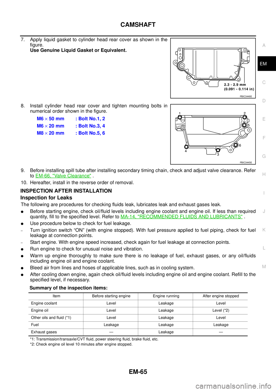
7. Apply liquid gasket to cylinder head rear cover as shown in the
figure.
Use Genuine Liquid Gasket or Equivalent.
8. Install cylinder head rear cover and tighten mounting bolts in
numerical order shown in the figure.
9. Before installing spill tube after installing secondary timing chain, check and adjust valve clearance. Refer
toEM-66, "
Valve Clearance".
10. Hereafter, install in the reverse order of removal.
INSPECTION AFTER INSTALLATION
Inspection for Leaks
The following are procedures for checking fluids leak, lubricates leak and exhaust gases leak.
lBefore starting engine, check oil/fluid levels including engine coolant and engine oil. If less than required
quantity, fill to the specified level. Refer toMA-14, "
RECOMMENDED FLUIDS AND LUBRICANTS".
lUse procedure below to check for fuel leakage.
–Turn ignition switch “ON” (with engine stopped). With fuel pressure applied to fuel piping, check for fuel
leakage at connection points.
–Start engine. With engine speed increased, check again for fuel leakage at connection points.
lRun engine to check for unusual noise and vibration.
lWarm up engine thoroughly to make sure there is no leakage of fuel, exhaust gases, or any oil/fluids
including engine oil and engine coolant.
lBleed air from lines and hoses of applicable lines, such as in cooling system.
lAfter cooling down engine, again check oil/fluid levels including engine oil and engine coolant. Refill to the
specified level, if necessary.
Summary of the inspection items:
*1: Transmission/transaxle/CVT fluid, power steering fluid, brake fluid, etc.
*2: Check engine oil level 10 minutes after engine stopped.
PBIC3446E
M6´50 mm : Bolt No.1, 2
M6´20 mm : Bolt No.3, 4
M8´20 mm : Bolt No.5, 6
PBIC3445E
Item Before starting engine Engine running After engine stopped
Engine coolant Level Leakage Level
Engine oil Level Leakage Level (*2)
Other oils and fluid (*1) Level Leakage Level
Fuel Leakage Leakage Leakage
Exhaust gases — Leakage —
Page 1460 of 3171

EM-78
SECONDARY TIMING CHAIN
Summary of the inspection items:
*1: Transmission/transaxle/CVT fluid, power steering fluid, brake fluid, etc.
*2: Check engine oil level 10 minutes after engine stopped.Item Before starting engine Engine running After engine stopped
Engine coolant Level Leakage Level
Engine oil Level Leakage Level (*2)
Other oils and fluid (*1) Level Leakage Level
Fuel Leakage Leakage Leakage
Exhaust gases — Leakage —
Page 1473 of 3171
PRIMARY TIMING CHAIN
EM-91
C
D
E
F
G
H
I
J
K
L
MA
EM
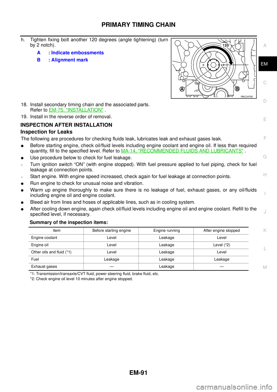
h. Tighten fixing bolt another 120 degrees (angle tightening) (turn
by 2 notch).
18. Install secondary timing chain and the associated parts.
Refer toEM-75, "
INSTALLATION".
19. Install in the reverse order of removal.
INSPECTION AFTER INSTALLATION
Inspection for Leaks
The following are procedures for checking fluids leak, lubricates leak and exhaust gases leak.
lBefore starting engine, check oil/fluid levels including engine coolant and engine oil. If less than required
quantity, fill to the specified level. Refer toMA-14, "
RECOMMENDED FLUIDS AND LUBRICANTS".
lUse procedure below to check for fuel leakage.
–Turn ignition switch “ON” (with engine stopped). With fuel pressure applied to fuel piping, check for fuel
leakage at connection points.
–Start engine. With engine speed increased, check again for fuel leakage at connection points.
lRun engine to check for unusual noise and vibration.
lWarm up engine thoroughly to make sure there is no leakage of fuel, exhaust gases, or any oil/fluids
including engine oil and engine coolant.
lBleed air from lines and hoses of applicable lines, such as in cooling system.
lAfter cooling down engine, again check oil/fluid levels including engine oil and engine coolant. Refill to the
specified level, if necessary.
Summary of the inspection items:
*1: Transmission/transaxle/CVT fluid, power steering fluid, brake fluid, etc.
*2: Check engine oil level 10 minutes after engine stopped.
A : Indicate embossments
B : Alignment mark
PBIC3476E
Item Before starting engine Engine running After engine stopped
Engine coolant Level Leakage Level
Engine oil Level Leakage Level (*2)
Other oils and fluid (*1) Level Leakage Level
Fuel Leakage Leakage Leakage
Exhaust gases — Leakage —