Page 2950 of 3171
FRONT PASSENGER AIR BAG MODULE
SRS-41
C
D
E
F
G
I
J
K
L
MA
B
SRS
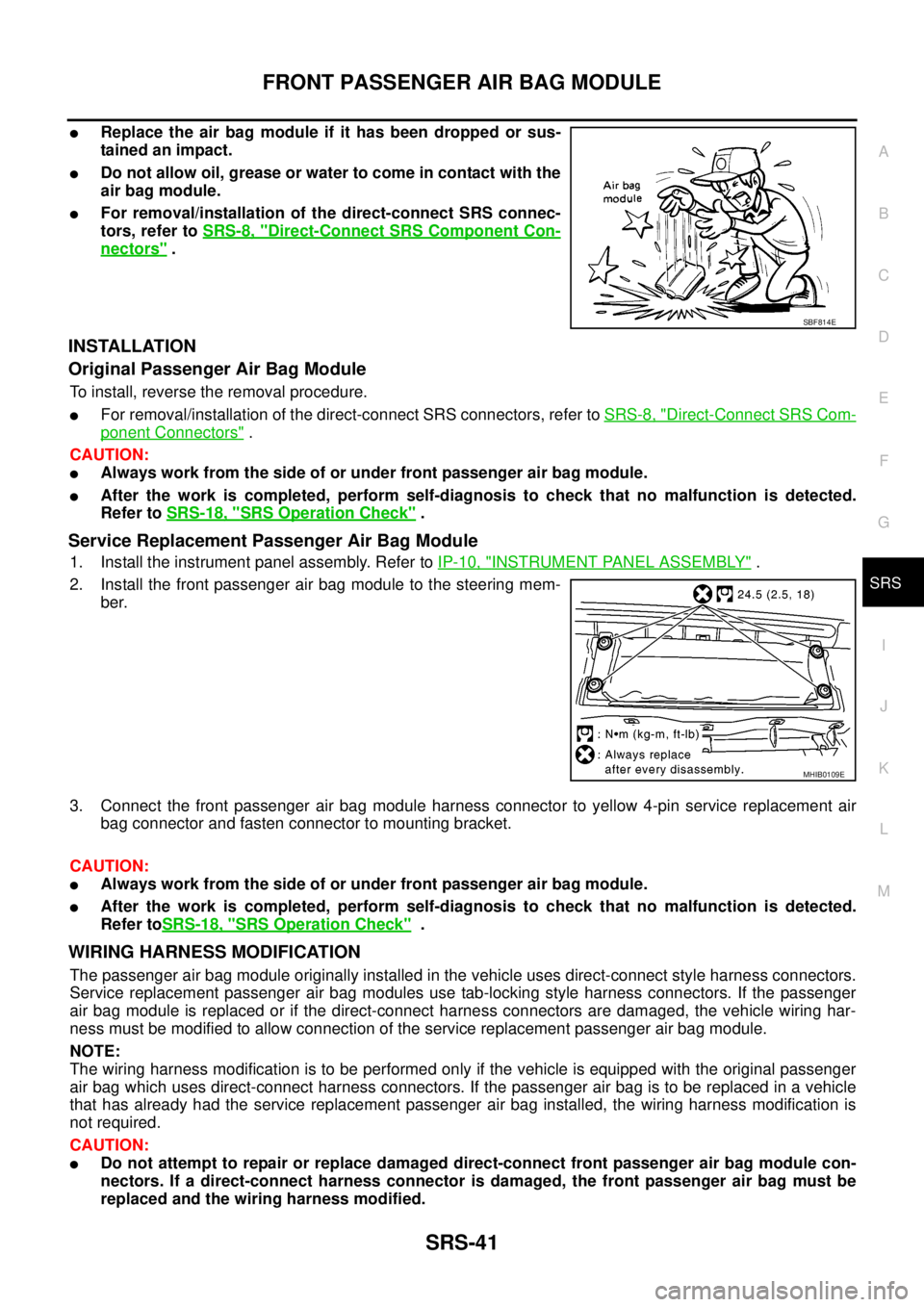
lReplace the air bag module if it has been dropped or sus-
tainedanimpact.
lDo not allow oil, grease or water to come in contact with the
air bag module.
lFor removal/installation of the direct-connect SRS connec-
tors, refer toSRS-8, "
Direct-Connect SRS Component Con-
nectors".
INSTALLATION
Original Passenger Air Bag Module
To install, reverse the removal procedure.
lFor removal/installation of the direct-connect SRS connectors, refer toSRS-8, "Direct-Connect SRS Com-
ponent Connectors".
CAUTION:
lAlways work from the side of or under front passenger air bag module.
lAfter the work is completed, perform self-diagnosis to check that no malfunction is detected.
Refer toSRS-18, "
SRS Operation Check".
Service Replacement Passenger Air Bag Module
1. Install the instrument panel assembly. Refer toIP-10, "INSTRUMENT PANEL ASSEMBLY".
2. Install the front passenger air bag module to the steering mem-
ber.
3. Connect the front passenger air bag module harness connector to yellow 4-pin service replacement air
bag connector and fasten connector to mounting bracket.
CAUTION:
lAlways work from the side of or under front passenger air bag module.
lAfter the work is completed, perform self-diagnosis to check that no malfunction is detected.
Refer toSRS-18, "
SRS Operation Check".
WIRING HARNESS MODIFICATION
The passenger air bag module originally installed in the vehicle uses direct-connect style harness connectors.
Service replacement passenger air bag modules use tab-locking style harness connectors. If the passenger
air bag module is replaced or if the direct-connect harness connectors are damaged, the vehicle wiring har-
ness must be modified to allow connection of the service replacement passenger air bag module.
NOTE:
The wiring harness modification is to be performed only if the vehicle is equipped with the original passenger
air bag which uses direct-connect harness connectors. If the passenger air bag is to be replaced in a vehicle
that has already had the service replacement passenger air bag installed, the wiring harness modification is
not required.
CAUTION:
lDo not attempt to repair or replace damaged direct-connect front passenger air bag module con-
nectors. If a direct-connect harness connector is damaged, the front passenger air bag must be
replaced and the wiring harness modified.
SBF814E
MHIB0109E
Page 2951 of 3171
SRS-42
FRONT PASSENGER AIR BAG MODULE
lBefore servicing SRS, turn the ignition switch off, disconnect both battery cables and wait at least
3 minutes.
lAlways work from the side of or under front passenger air bag module.
lAfter the work is completed, perform self-diagnosis to check that no malfunction is detected.
Refer toSRS-18, "
SRS Operation Check".
1. Locate the yellow and orange direct-connect passenger air bag module harness connectors.
2. Use wire cutters to cut back both previously used direct-connect passenger air bag module harness con-
nectors from the vehicle wiring harness approximately 50 mm (1.9 in) from the connectors.
3. Remove approximately 150 mm (5.9 in) of the vehicle harness covering from the cut end.
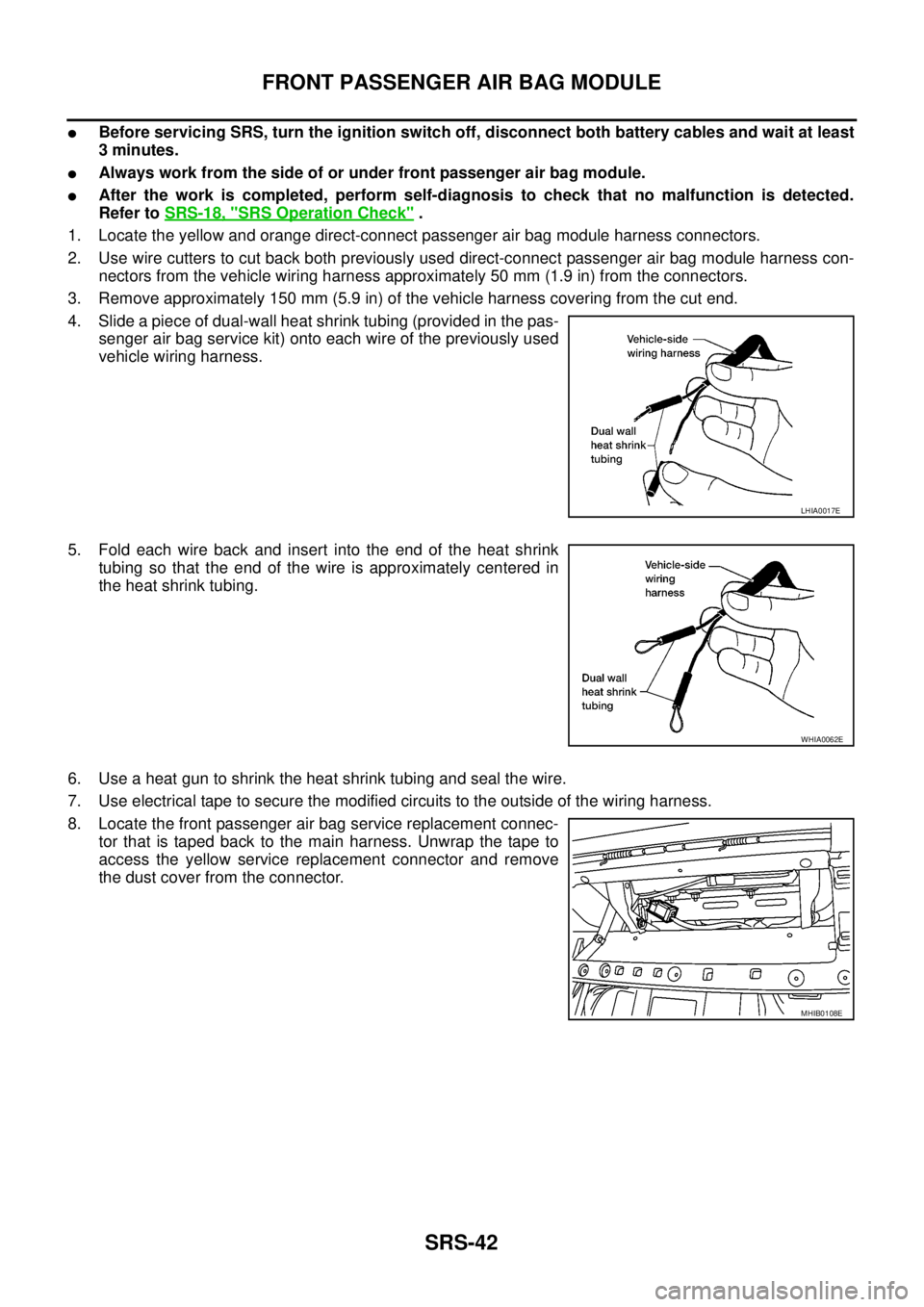
4. Slide a piece of dual-wall heat shrink tubing (provided in the pas-
senger air bag service kit) onto each wire of the previously used
vehicle wiring harness.
5. Fold each wire back and insert into the end of the heat shrink
tubing so that the end of the wire is approximately centered in
the heat shrink tubing.
6. Use a heat gun to shrink the heat shrink tubing and seal the wire.
7. Use electrical tape to secure the modified circuits to the outside of the wiring harness.
8. Locate the front passenger air bag service replacement connec-
tor that is taped back to the main harness. Unwrap the tape to
access the yellow service replacement connector and remove
the dust cover from the connector.
LHIA0017E
WHIA0062E
MHIB0108E
Page 2952 of 3171
FRONT SIDE AIR BAG MODULE
SRS-43
C
D
E
F
G
I
J
K
L
MA
B
SRS
FRONT SIDE AIR BAG MODULEPFP:K8EH0
Removal and InstallationEHS001XV
REMOVAL
WARNING:
Removal of front side air bag module should only be done to allow deployment of front side air bag
module prior to disposal of seatback assembly.
Only complete seatback assemblies can be replaced. Refer toSE-26, "
SEATBACK (POWER AND MAN-
UAL SEAT)"andSE-27, "SEATBACK (FRAT FOLD SEAT)".
CAUTION:
lBefore servicing the SRS, turn the ignition switch off, disconnect both battery cables and wait at
least 3 minutes.
lWhen servicing the SRS, do not work from directly in front of air bag module.
1. Remove the front seat. Refer toSE-23, "
REMOVAL".
2. Remove the seatback trim and pad. Refer toSE-26, "
SEATBACK (POWER AND MANUAL SEAT)"and
SE-27, "
SEATBACK (FRAT FOLD SEAT)".
3. Remove the seatback rear finisher and remove the retainers securing the seat cushion trim. Refer toSE-
24, "SEAT CUSHION (POWER SEAT)"andSE-25, "SEAT CUSHION (MANUAL SEAT)".
4. Remove air bag module harness clips.
5. Remove the fasteners from the front side air bag module and remove the front side air bag module.
CAUTION:
lWhen using a clip removal tool to remove the seatback
board, take care not to damage the harness for front side air
bag module.
lWhen servicing the SRS, do not work from directly in front
of air bag module.
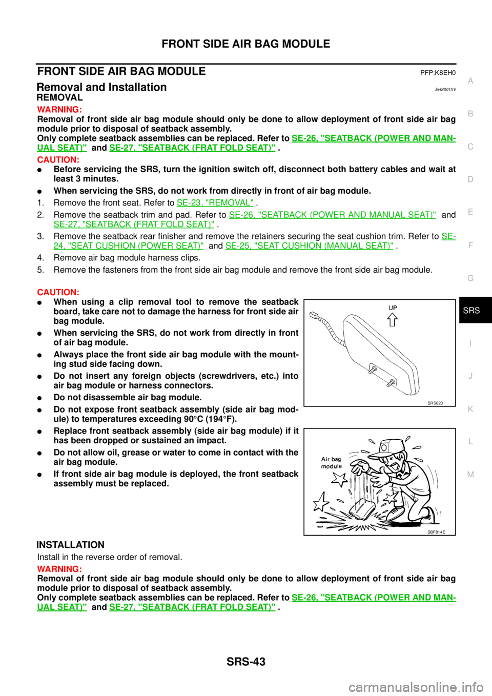
lAlways place the front side air bag module with the mount-
ing stud side facing down.
lDo not insert any foreign objects (screwdrivers, etc.) into
air bag module or harness connectors.
lDo not disassemble air bag module.
lDo not expose front seatback assembly (side air bag mod-
ule) to temperatures exceeding 90°C(194°F).
lReplace front seatback assembly (side air bag module) if it
has been dropped or sustained an impact.
lDo not allow oil, grease or water to come in contact with the
air bag module.
lIf front side air bag module is deployed, the front seatback
assembly must be replaced.
INSTALLATION
Install in the reverse order of removal.
WARNING:
Removal of front side air bag module should only be done to allow deployment of front side air bag
module prior to disposal of seatback assembly.
Only complete seatback assemblies can be replaced. Refer toSE-26, "
SEATBACK (POWER AND MAN-
UAL SEAT)"andSE-27, "SEATBACK (FRAT FOLD SEAT)".
SRS623
SBF814E
Page 2953 of 3171
SRS-44
SIDE CURTAIN AIR BAG MODULE
SIDE CURTAIN AIR BAG MODULE
PFP:985P0
Removal and InstallationEHS001XW
REMOVAL
CAUTION:
lDo not attempt to repair or replace damaged direct-connect SRS component connectors. If a
direct-connect harness connector is damaged, the harness must be replaced.
lBefore servicing the SRS, turn the ignition switch off, disconnect both battery cables and wait at
least 3 minutes.
lWhen servicing the SRS, do not work from directly in front of air bag module.
1. Remove headlining. Refer toEI-40, "
Removal and Installation".
2. Disconnect side curtain air bag module connectors.
lFor removal/installation of the direct-connect SRS connectors, refer toSRS-8, "Direct-Connect SRS
Component Connectors".
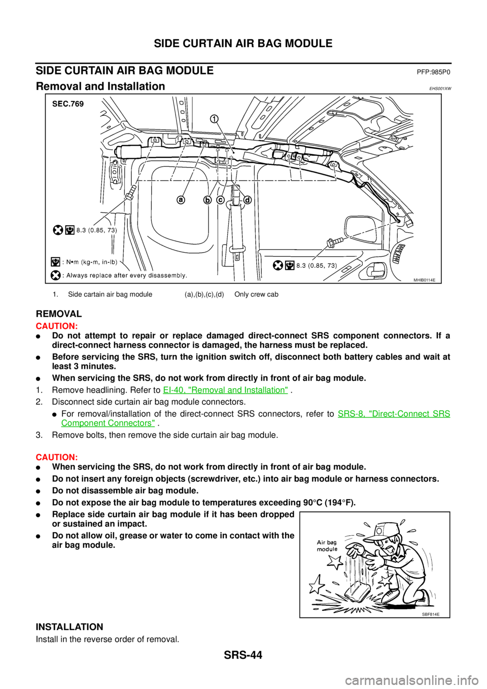
3. Remove bolts, then remove the side curtain air bag module.
CAUTION:
lWhen servicing the SRS, do not work from directly in front of air bag module.
lDo not insert any foreign objects (screwdriver, etc.) into air bag module or harness connectors.
lDo not disassemble air bag module.
lDo not expose the air bag module to temperatures exceeding 90°C(194°F).
lReplace side curtain air bag module if it has been dropped
or sustained an impact.
lDo not allow oil, grease or water to come in contact with the
air bag module.
INSTALLATION
Install in the reverse order of removal.
MHIB0114E
1. Side cartain air bag module (a),(b),(c),(d) Only crew cab
SBF814E
Page 2954 of 3171
SIDE CURTAIN AIR BAG MODULE
SRS-45
C
D
E
F
G
I
J
K
L
MA
B
SRS
lFor removal/installation of the direct-connect SRS connectors, refer toSRS-8, "Direct-Connect SRS Com-
ponent Connectors".
lAfter replacement of side curtain air bag module, perform self-diagnosis to check that no malfunction is
detected. Refer toSRS-18, "
SRS Operation Check".
Page 2955 of 3171
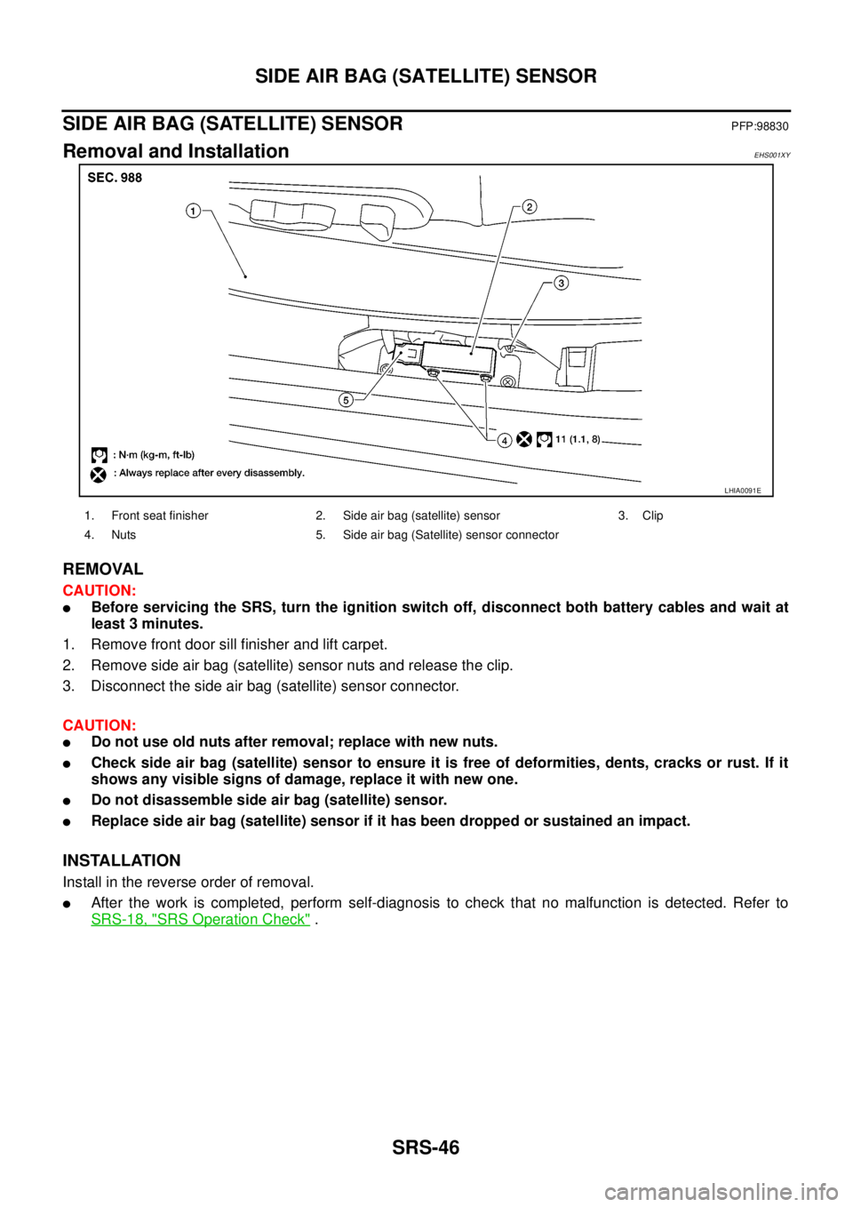
SRS-46
SIDE AIR BAG (SATELLITE) SENSOR
SIDE AIR BAG (SATELLITE) SENSOR
PFP:98830
Removal and InstallationEHS001XY
REMOVAL
CAUTION:
lBefore servicing the SRS, turn the ignition switch off, disconnect both battery cables and wait at
least 3 minutes.
1. Remove front door sill finisher and lift carpet.
2. Remove side air bag (satellite) sensor nuts and release the clip.
3. Disconnect the side air bag (satellite) sensor connector.
CAUTION:
lDo not use old nuts after removal; replace with new nuts.
lCheck side air bag (satellite) sensor to ensure it is free of deformities, dents, cracks or rust. If it
shows any visible signs of damage, replace it with new one.
lDo not disassemble side air bag (satellite) sensor.
lReplace side air bag (satellite) sensor if it has been dropped or sustained an impact.
INSTALLATION
Install in the reverse order of removal.
lAfter the work is completed, perform self-diagnosis to check that no malfunction is detected. Refer to
SRS-18, "
SRS Operation Check".
LHIA0091E
1. Front seat finisher 2. Side air bag (satellite) sensor 3. Clip
4. Nuts 5. Side air bag (Satellite) sensor connector
Page 2956 of 3171
FRONT SEAT BELT PRE-TENSIONER
SRS-47
C
D
E
F
G
I
J
K
L
MA
B
SRS
FRONT SEAT BELT PRE-TENSIONERPFP:86884
Removal and InstallationEHS001XZ
For removal and installation procedures, refer toSB-3, "Removal and Installation of Front Seat Belt - King
Cab".andSB-5, "Removal and Installation of Front Seat Belt - Double Cab".
Page 2957 of 3171
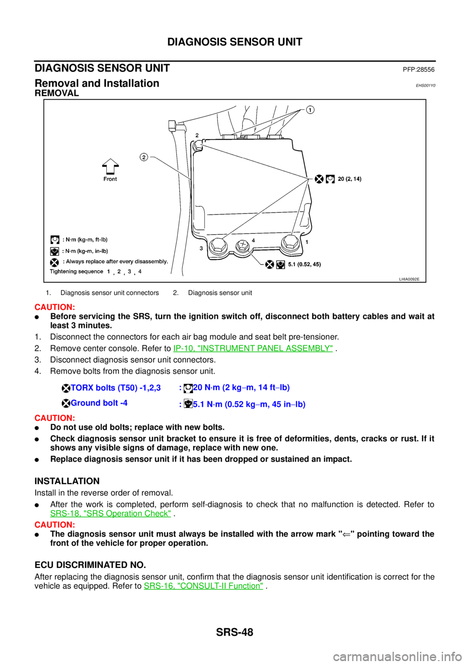
SRS-48
DIAGNOSIS SENSOR UNIT
DIAGNOSIS SENSOR UNIT
PFP:28556
Removal and InstallationEHS001Y0
REMOVAL
CAUTION:
lBefore servicing the SRS, turn the ignition switch off, disconnect both battery cables and wait at
least 3 minutes.
1. Disconnect the connectors for each air bag module and seat belt pre-tensioner.
2. Remove center console. Refer toIP-10, "
INSTRUMENT PANEL ASSEMBLY".
3. Disconnect diagnosis sensor unit connectors.
4. Remove bolts from the diagnosis sensor unit.
CAUTION:
lDo not use old bolts; replace with new bolts.
lCheck diagnosis sensor unit bracket to ensure it is free of deformities, dents, cracks or rust. If it
shows any visible signs of damage, replace with new one.
lReplace diagnosis sensor unit if it has been dropped or sustained an impact.
INSTALLATION
Install in the reverse order of removal.
lAfter the work is completed, perform self-diagnosis to check that no malfunction is detected. Refer to
SRS-18, "
SRS Operation Check".
CAUTION:
lThe diagnosis sensor unit must always be installed with the arrow mark "Ü" pointing toward the
front of the vehicle for proper operation.
ECU DISCRIMINATED NO.
After replacing the diagnosis sensor unit, confirm that the diagnosis sensor unit identification is correct for the
vehicle as equipped. Refer toSRS-16, "
CONSULT-II Function".
LHIA0092E
1. Diagnosis sensor unit connectors 2. Diagnosis sensor unit
TORX bolts (T50) -1,2,3:20N·m(2kg-m, 14 ft-lb)
Ground bolt -4
: 5.1 N·m (0.52 kg-m, 45 in-lb)