Page 77 of 364
INTAKE & EXHAUST INTER-COOLER WATER SPRAY
15-3
Fitting guidelines
� �
A� �
Fitting the water spray hose ASSY and fixing tape (for securing the water spray hose ASSY)
1. After fitting the water spray hose, the three-way joint and the washer valve, affix pads, clips and tape at the positions
shown in the water spray hose diagram.
2. Fit the water spray hose ASSY to the front bumper using the water spray hose ASSY clip.
3. Affix tape as shown in the diagram, so that the water spray hose ASSY does not slip.
View of the inside of the front bumper
tape
three-way joint
pads
tape
washer
valve
clip
tapeclip
three-way joint
padclip
washer valve
tape
clip
tape
clipclip
water spray hose ASSY
water spray
nozzle brackets
tape
Page 78 of 364
INTAKE & EXHAUST – SECONDARY AIR CONTROL SYSTEM15-4
Secondary air control system
Removal and fitting
Jobs to be completed before removal and after fitting
• Removal and refitting of the air duct
• Removal and refitting of the strut tower bar
Removal procedure
1. Control harness connection
2. Heat protector
3. Vacuum hose connection
• Air pipe C
4. Vacuum pipe
5. Harness bracket6. Air hose
7. Air pipe ASSY
8. Gasket
9. Gasket
10. Secondary air control valve
11.Harness bracket
air pipe C
�
�
A� �
Page 79 of 364
INTAKE & EXHAUST – SECONDARY AIR CONTROL SYSTEM, INLET MANIFOLD15-5
Fitting guidelines
� �
A� �
Fitting the gasket
Fit the gasket so that the protruding part points in the direction
shown in the diagram.
Inlet manifold
Removal and fitting
Jobs to be completed before removal and
after fitting
•Take measures to prevent fuel leaking (only
before removal)
•Removal and refitting of the valence (Ref
Section 15: Front bumper)
•Draining and refilling the coolant
•Removal and refitting of the air duct•Removal and refitting of the strut tower bar
•Removal and refitting of the throttle body
•Removal and refitting of the secondary air
control valve (Ref P15-4)
•Removal and refitting of the cross member bar
•Removal and refitting of the front exhaust pipe
protruding
part
(engine oil)
(engine oil)
Page 80 of 364
INTAKE & EXHAUST – INLET MANIFOLD15-6
Removal procedure
1. Centre cover
2. Ignition coil connector
3. O
2sensor connector
4. Oil feeder control valve connector
5. Crank angle sensor connector
6. Injector connector
7. Air temperature sensor connector
8. Manifold absolute pressure sensor
connector
9. Purge control solenoid valve connector
10. Knock sensor connector
11.Fuel pressure solenoid valve connector12. Vacuum hose connection
13. Vacuum hose connection
14. Fuel return hose connection
15. Fuel high pressure hose connection
16. O-ring
17. Delivery pipe, injector and fuel pressure
regulator ASSY
18. Insulator
19. Insulator
20. Oil level gauge & guide ASSY
21. O-ring
22. Brake booster vacuum hose connection
23. Purge hose connection
� �
A� �
� �
A� �
�
�
A� �
Page 81 of 364

INTAKE & EXHAUST – INLET MANIFOLD
15-7
Removal procedure
24. Knock sensor connector
25. Purge control solenoid valve ASSY
26. Vacuum hose
27. Fuel pressure solenoid valve ASSY
28. PCV hose
•Alternator (Ref Section 16: Alternator)
29. Secondary air control solenoid valve
connector
30. Vacuum tank, ACV solenoid valve,
vacuum hose & pipe ASSY31. Inlet manifold stay
32. Cover
33. Gasket
34. Harness connection
35. Crank angle sensor connector
36. Alternator bracket
37. Inlet manifold
38. Inlet manifold gasket
Removal guidelines
� �
A� �
Removal of the delivery pipe, the injector and the fuel
pressure regulator ASSY
Remove the deliver pipe, with the injector and the fuel pressure
regulator intact.
Caution
When removing the delivery pipe, be careful not to drop the
injector.
Fitting guidelines
� �
A� �
Connecting the O-ring and the fuel high pressure hose
1. Apply a small quantity of fresh engine oil to the O-ring, and
insert it into the delivery pipe without damaging the O-ring.
2. Check that the high pressure hose can be turned smoothly. If it
cannot be turned smoothly there is a possibility that it is biting
into the O-ring, so remove the high pressure hose and check for
any damage to the O-ring. If the O-ring is undamaged, reinsert it
into the delivery pipe and check once more whether the hose
can be turned smoothly.
3. Tighten the mounting bolt to the specified torque.
Tightening torque: 5.0 ± 1.0 N·m
Page 82 of 364
INTAKE & EXHAUST – EXHAUST MANIFOLD & TURBOCHARGER15-8
Exhaust manifold and turbocharger
Removal and fitting
Jobs to be completed before removal and after
fitting
• Removal and refitting of the valence
• Removal and refitting of the radiator
• Removal and refitting of the air intake hose and
air hose A• Removal and refitting of the cross member bar
• Removal and refitting of the front exhaust pipe
• Draining and refilling of the engine oil
Page 83 of 364

INTAKE & EXHAUST – EXHAUST MANIFOLD15-9
Removal procedure
1. Exhaust manifold heat protector
2. Air pipe ASSY connection
3. O
2sensor
4. Turbocharger heat protector
5. Turbocharger water feed pipe connection
6. Gasket
7. Water hose connection
8. Oil feed pipe
9. Gasket
10. Starter
11.Oil return pipe
12. Oil return pipe gasket (turbocharger side)
13. Oil return pipe gasket (oil pan side)14. Vacuum hose connection
15. Air outlet fitting
16. Air outlet fitting gasket
17. Exhaust fitting bracket
18. Turbocharger and exhaust fitting ASSY
19. Turbocharger ASSY
20. Exhaust fitting gasket
21. Exhaust fitting
22. Turbocharger gasket
23. Turbocharger water return pipe
24. Gasket
25. Exhaust manifold
26. Exhaust manifold gasket
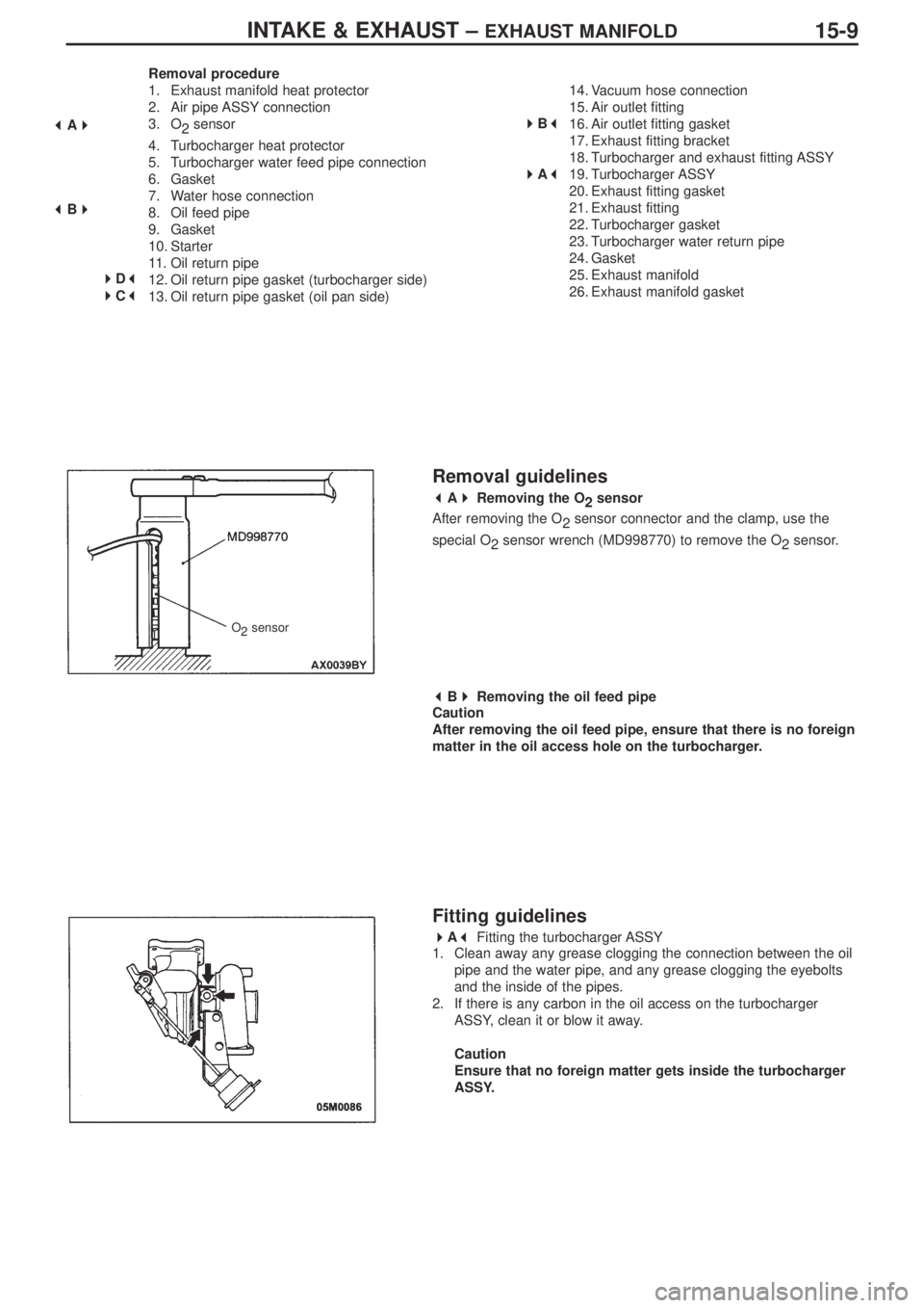
Removal guidelines
� �
A� �
Removing the O
2sensor
After removing the O
2sensor connector and the clamp, use the
special O
2 sensor wrench (MD998770) to remove the O
2sensor.
� �
B� �
Removing the oil feed pipe
Caution
After removing the oil feed pipe, ensure that there is no foreign
matter in the oil access hole on the turbocharger.
Fitting guidelines
� �
A� �
Fitting the turbocharger ASSY
1. Clean away any grease clogging the connection between the oil
pipe and the water pipe, and any grease clogging the eyebolts
and the inside of the pipes.
2. If there is any carbon in the oil access on the turbocharger
ASSY, clean it or blow it away.
Caution
Ensure that no foreign matter gets inside the turbocharger
ASSY.
� �
A� �
� �
B� �
�
�
D� �
� �
C� �
�
�
B� �
� �
A� �
O
2sensor
Page 84 of 364
INTAKE & EXHAUST – EXHAUST MANIFOLD15-10
� �
B� �
Fitting the air outlet fitting gasket
Fit the gasket so that the protruding part is in the position located in
the diagram.
� �
C� �
Fitting the oil return pipe gasket (oil pan side)
Fit so that the printed side of the gasket is on the oil pan side.
� �
D� �
Fitting the oil return pipe gasket (turbocharger side)
Fit so that the printed side of the gasket is on the turbocharger side.turbocharger
protruding part
view “A”
view “A”
print
print
gasket
gasket
3. Apply some fresh engine oil via the fitting hole for the oil feed
pipe in the turbocharger ASSY.