Page 36 of 364
ENGINE – ENGINE ASSY11-30
Caution
Parts marked * should be temporarily tightened, and then tightened properly when the full weight of the engine is
being supported by the chassis.
20. Vacuum tank, solenoid valve, vacuum
pipe and hose ASSY
21. Brake booster vacuum hose connection
22. Purge hose connection
23. Power steering oil pressure switch
connector
24. Heat protector
25. Power steering oil pump
26. A/C compressor connector
27. A/C compressor
A/C>28. Heater hose connection
29. Fuel return hose connection
30. Fuel high pressure hose connection
31. O-ring
•Transfer ASSY, transmission ASSY
32. Engine mount bracket & stopper ASSY
33. Engine ASSY
� �
B� �
� �
B� �
�
�
D� �
� �
D� �
� �
C� �
�
�
C� �
� �
D� �
�
�
B� �
� �
E� �
�
�
A� �
(engine oil)
Page 42 of 364

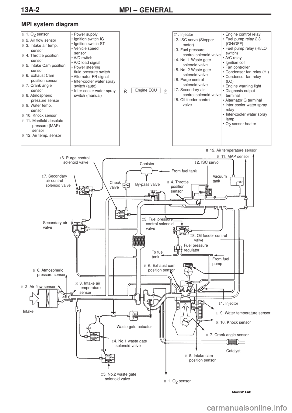
MPI – GENERAL13A-2
MPI system diagram
Engine ECU
H1. O
2 sensor
H2. Air flow sensor
H3. Intake air temp.
sensor
H4. Throttle position
sensor
H5. Intake Cam position
sensor
H6. Exhaust Cam
position sensor
H7. Crank angle
sensor
H8. Atmospheric
pressure sensor
H9. Water temp.
sensor
H10. Knock sensor
H11. Manifold absolute
pressure (MAP)
sensor
H12. Air temp. sensor• Power supply
• Ignition switch IG
• Ignition switch ST
• Vehicle speed
sensor
• A/C switch
• A/C load signal
• Power steering
fluid pressure switch
• Alternator FR signal
• Inter-cooler water spray
switch (auto)
•Inter-cooler water spray
switch (manual)I1. Injector
I2. ISC servo (Stepper
motor)
I3. Fuel pressure
control solenoid valve
I4. No. 1 Waste gate
solenoid valve
I5. No. 2 Waste gate
solenoid valve
I6. Purge control
solenoid valve
I7. Secondary air
control solenoid valve
I8. Oil feeder control
valve• Engine control relay
• Fuel pump relay 2,3
(ON/OFF)
• Fuel pump relay (HI/LO
switch)
• A/C relay
• Ignition coil
• Fan controller
• Condenser fan relay (HI)
• Condenser fan relay
(LO)
• Engine warning light
• Diagnosis output
terminal
• Alternator G terminal
• Inter-cooler water spray
relay
•Inter-cooler water spray
lamp
• O
2sensor heater
ÈÈ
I 6. Purge control
solenoid valve
I 7. Secondary
air control
solenoid valveCheck
valve
Secondary air
valve
To fuel
tank
H 6. Exhaust cam
position sensor
H 8. Atmospheric
pressure sensor
H 2. Air flow sensor
Intake
Waste gate actuator
I 4. No.1 waste gate
solenoid valve H 3. Intake air
temperature
sensor
I 5. No.2 waste gate
solenoid valve
H 1. O
2sensor
H 5. Intake cam
position sensorCatalyst
H 7. Crank angle sensor
H 10. Knock sensor
H 9. Water temperature sensor
I 1. Injector From fuel
pump
Fuel pressure
regulatorI 8. Oil feeder control
valve I 3. Fuel pressure
control solenoid
valve
Vacuum
tank
I 2. ISC servoH 11. MAP sensor
H 12. Air temperature sensor
H 4. Throttle
position
sensor
From fuel tank
Canister
By-pass valve
Page 69 of 364

13A-29MPI – TROUBLESHOOTING, ON-VEHICLE SERVICING
•Example 2
Waveform characteristics
The waveform is displaced to the left or the right.
Cause of the problem
The timing belt is loose
There is an abnormality in the fuel pump camshaft
On-vehicle servicing
1. Adjusting standard engine revolutions
when idling
The standard engine revolutions when idling have been
changed. All other servicing requirements are the same as
before.
Standard engine revolutions when idling: 800 ± 50 r/min
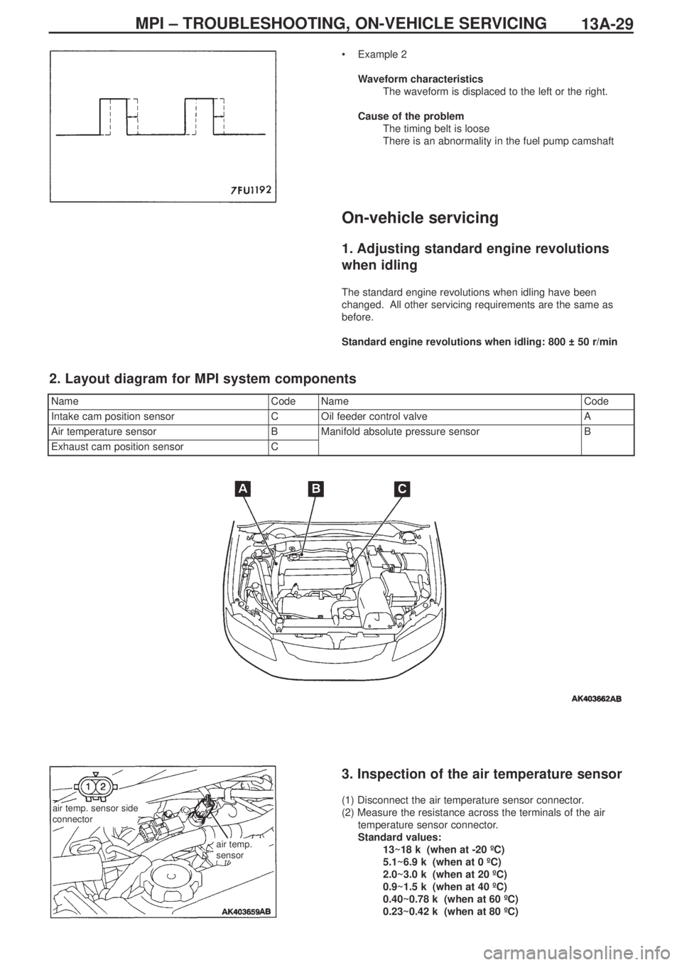
NameCodeNameCode
Intake cam position sensorCOil feeder control valveA
Air temperature sensorBManifold absolute pressure sensorB
Exhaust cam position sensorC
2. Layout diagram for MPI system components
air temp. sensor side
connector
air temp.
sensor
3. Inspection of the air temperature sensor
(1) Disconnect the air temperature sensor connector.
(2) Measure the resistance across the terminals of the air
temperature sensor connector.
Standard values:
13~18 kΩ (when at -20 ºC)
5.1~6.9 kΩ (when at 0 ºC)
2.0~3.0 kΩ (when at 20 ºC)
0.9~1.5 kΩ (when at 40 ºC)
0.40~0.78 kΩ (when at 60 ºC)
0.23~0.42 kΩ (when at 80 ºC)
Page 86 of 364
ENGINE ELECTRICAL – CHARGING SYSTEM16-2
Removal procedure
1. Injector connector
2. Accelerator cable connection
3. Delivery pipe, injector, and fuel pressure
regulator ASSY
4. Insulator
5. Insulator
6. Fuel pressure solenoid valve connector
7. Fuel pressure solenoid valve ASSY
8. Knock sensor connector
9. Purge control solenoid valve connector10. Purge control solenoid valve ASSY
11.Oil level gauge and guide ASSY
12. O-ring
13. Drive belt
14. Alternator connector and terminal
• Engine mount
15. Alternator
16. Water pump pulley
17. O
2sensor connector
18. Alternator bracket
(engine oil)
� �
A� ��
�
B� �
� �
C� �
Page 108 of 364

Service Manual
4G6
FOREWORD
This manual contains information about the 4G6
DOHC engine. It only covers those points that are
different from the service manuals listed below.
Therefore, this manual should be used in conjunction
with the following manuals.
• 4G6 DOHC engine Service Manual (No. 1039G46)
• 4G6 DOHC engine Service Manual Supplement
(No.1039G63)
This manual is based on the engine specifications as of
March 2005. Please note that some engine details may
not match those given in this manual due to
subsequent changes in engine specifications. The units
shown in this manual are the standard international
SI units.
(However, conventional units are used for some figures
taken from existing documents)
If you have any opinions, requests or queries regarding
this manual, please write them down on the “Servicing
Comment Form” on the last page, and fax them to us.
March 2005
Mitsubishi Motor Corporation
This manual is printed on recycled paper.
CONTENTS
General Information . . . . . . . . . . . . . . . 4
Servicing Specification Values . . . . . . 4
Tightening torques . . . . . . . . . . . . . . . . 5
Sealants . . . . . . . . . . . . . . . . . . . . . . . . . 7
Alternator / Ignition system . . . . . . . . . 8
Timing belt . . . . . . . . . . . . . . . . . . . . . 10
Fuel system . . . . . . . . . . . . . . . . . . . . . 13
Secondary air system /
inlet manifold . . . . . . . . . . . . . . . . . . . 15
Exhaust manifold . . . . . . . . . . . . . . . . 16
Water pump / Water hose . . . . . . . . . 17
Rocker arm / Cam shaft . . . . . . . . . . . 18
Oil pump / Sump . . . . . . . . . . . . . . . . . 21
Pistons / Connecting rods . . . . . . . . . 22
Crank shaft / Cylinder block . . . . . . . 25
Turbocharger. . . . . . . . . . . . . . . . . . . . 27
DOHC
ENGINE
Page 112 of 364

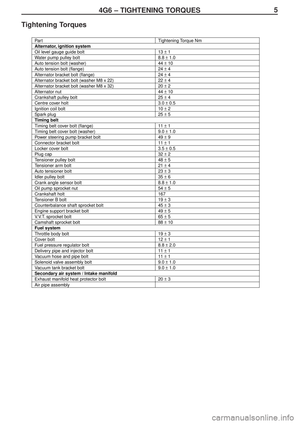
54G6 – TIGHTENING TORQUES
Tightening Torques
Par tTightening Torque Nm
Alternator, ignition system
Oil level gauge guide bolt13 ± 1
Water pump pulley bolt8.8 ± 1.0
Auto tension bolt (washer)44 ± 10
Auto tension bolt (flange)24 ± 4
Alternator bracket bolt (flange)24 ± 4
Alternator bracket bolt (washer M8 x 22)22 ± 4
Alternator bracket bolt (washer M8 x 32)20 ± 2
Alternator nut44 ± 10
Crankshaft pulley bolt25 ± 4
Centre cover holt3.0 ± 0.5
Ignition coil bolt10 ± 2
Spark plug25 ± 5
Timing belt
Timing belt cover bolt (flange)11 ± 1
Timing belt cover bolt (washer)9.0 ± 1.0
Power steering pump bracket bolt49 ± 9
Connector bracket bolt11 ± 1
Locker cover bolt3.5 ± 0.5
Plug cap32 ± 2
Tensioner pulley bolt48 ± 5
Tensioner arm bolt21 ± 4
Auto tensioner bolt23 ± 3
Idler pulley bolt35 ± 6
Crank angle sensor bolt8.8 ± 1.0
Oil pump sprocket nut54 ± 5
Crankshaft holt167
Tensioner B bolt19 ± 3
Counterbalance shaft sprocket bolt45 ± 3
Engine support bracket bolt49 ± 5
V.V.T. sprocket bolt65 ± 5
Camshaft sprocket bolt88 ± 10
Fuel system
Throttle body bolt19 ± 3
Cover bolt12 ± 1
Fuel pressure regulator bolt8.8 ± 2.0
Delivery pipe and injector bolt11 ± 1
Vacuum hose and pipe bolt11 ± 1
Solenoid valve assembly bolt9.0 ± 1.0
Vacuum tank bracket bolt9.0 ± 1.0
Secondary air system / Intake manifold
Exhaust manifold heat protector bolt20 ± 3
Air pipe assembly
Page 159 of 364
LAYOUT DIAGRAMS - ENGINE / TRANSMISSION1-9
B-126 (6-black) Idle speed control servo
B-127 (4) Electric pump relay
B-128 (4) Fuel pump relay 3
B-129 (6-black) Register (for injector)
B-130 (2-black) Fuel pump register
B-131 (3-black) Vehicle speed sensorB-132 (2-black) Back-up lamp switch
B-133 (2-black) Secondary air control solenoid valve
B-134 (2-black) Oil feeder control valve
B-135 (3-black) Manifold absolute pressure sensor
Ground cable
Transmission harness
Page 165 of 364
LAYOUT DIAGRAMS - INSTRUMENT PANEL1-15
C-214 (5) Blower relay
C-215 (15) Floor harness (RH) / J/B junction
C-216 (3) Roof harness / J/B junction
C-217 (4) Dummy connector
C-218 (4) Dummy connector
C-219 (4) Fuel pump relay 2
C-220 (4) Intercooler water spray relay
C-221 (4) Fuel pump relay 1C-222 (5) Power window relay
C-223 (2) Instrument panel harness / J/B junction
C-224 (20) ETACS-ECU
C-225 (24-grey) ETACS-ECU
C-226 (24) ETACS-ECU
C-228 (5) Steer sensor
(Front side)
Instrument panel harness
Dedicated fuse
Floor harness (RH)
Roof harness(Rear side)