Page 65 of 364
13A-25MPI – TROUBLESHOOTING 13A-24
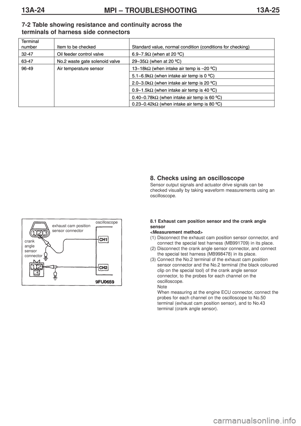
7-2 Table showing resistance and continuity across the
terminals of harness side connectors
8. Checks using an oscilloscope
Sensor output signals and actuator drive signals can be
checked visually by taking waveform measurements using an
oscilloscope.
crank
angle
sensor
connectorexhaust cam position
sensor connector
oscilloscope8.1 Exhaust cam position sensor and the crank angle
sensor
(1) Disconnect the exhaust cam position sensor connector, and
connect the special test harness (MB991709) in its place.
(2) Disconnect the crank angle sensor connector, and connect
the special test harness (MB998478) in its place.
(3) Connect the No.2 terminal of the exhaust cam position
sensor connector and the No.2 terminal (the black coloured
clip on the special tool) of the crank angle sensor
connector, to the probes for each channel on the
oscilloscope.
Note
When measuring at the engine ECU connector, connect the
probes for each channel on the oscilloscope to No.50
terminal (exhaust cam position sensor), and to No.43
terminal (crank angle sensor).
Page 66 of 364
13A-26MPI – TROUBLESHOOTING
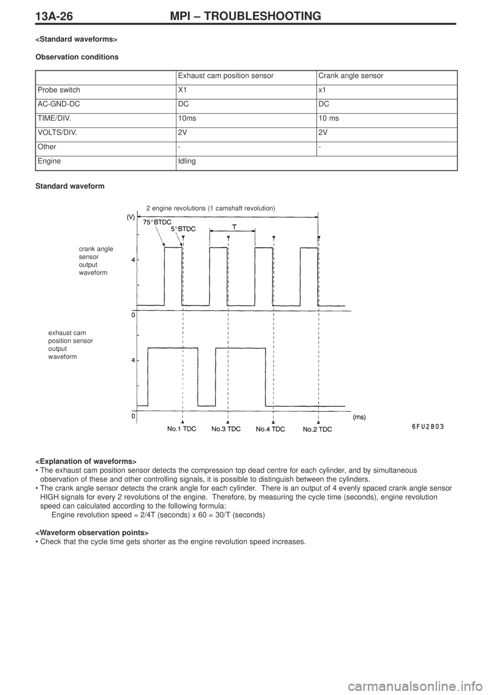
Observation conditions
Exhaust cam position sensorCrank angle sensor
Probe switchX1x1
AC-GND-DCDCDC
TIME/DIV.10ms10 ms
VOLTS/DIV.2V2V
Other--
EngineIdling
2 engine revolutions (1 camshaft revolution)
crank angle
sensor
output
waveform
exhaust cam
position sensor
output
waveform
Standard waveform
•The exhaust cam position sensor detects the compression top dead centre for each cylinder, and by simultaneous
observation of these and other controlling signals, it is possible to distinguish between the cylinders.
•The crank angle sensor detects the crank angle for each cylinder. There is an output of 4 evenly spaced crank angle sensor
HIGH signals for every 2 revolutions of the engine. Therefore, by measuring the cycle time (seconds), engine revolution
speed can calculated according to the following formula:
Engine revolution speed = 2/4T (seconds) x 60 = 30/T (seconds)
•Check that the cycle time gets shorter as the engine revolution speed increases.
Page 67 of 364
13A-27MPI – TROUBLESHOOTING
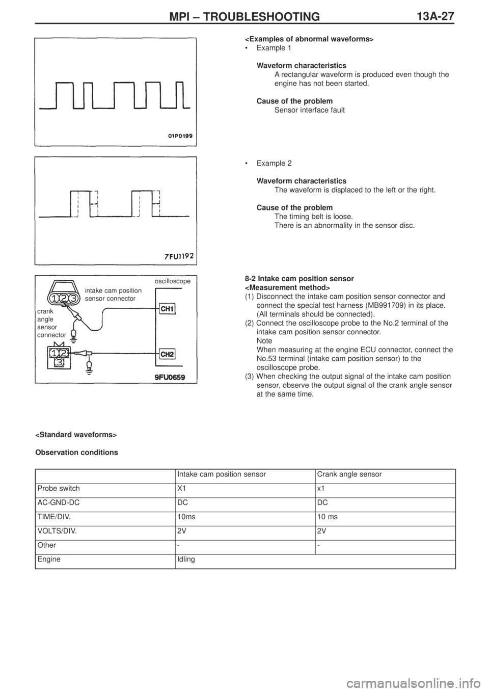
•Example 1
Waveform characteristics
Arectangular waveform is produced even though the
engine has not been started.
Cause of the problem
Sensor interface fault
•Example 2
Waveform characteristics
The waveform is displaced to the left or the right.
Cause of the problem
The timing belt is loose.
There is an abnormality in the sensor disc.
8-2 Intake cam position sensor
(1) Disconnect the intake cam position sensor connector and
connect the special test harness (MB991709) in its place.
(All terminals should be connected).
(2) Connect the oscilloscope probe to the No.2 terminal of the
intake cam position sensor connector.
Note
When measuring at the engine ECU connector, connect the
No.53 terminal (intake cam position sensor) to the
oscilloscope probe.
(3) When checking the output signal of the intake cam position
sensor, observe the output signal of the crank angle sensor
at the same time.
crank
angle
sensor
connector
intake cam position
sensor connectoroscilloscope
Observation conditions
Intake cam position sensorCrank angle sensor
Probe switchX1x1
AC-GND-DCDCDC
TIME/DIV.10ms10 ms
VOLTS/DIV.2V2V
Other--
EngineIdling
Page 68 of 364
13A-28MPI – TROUBLESHOOTING
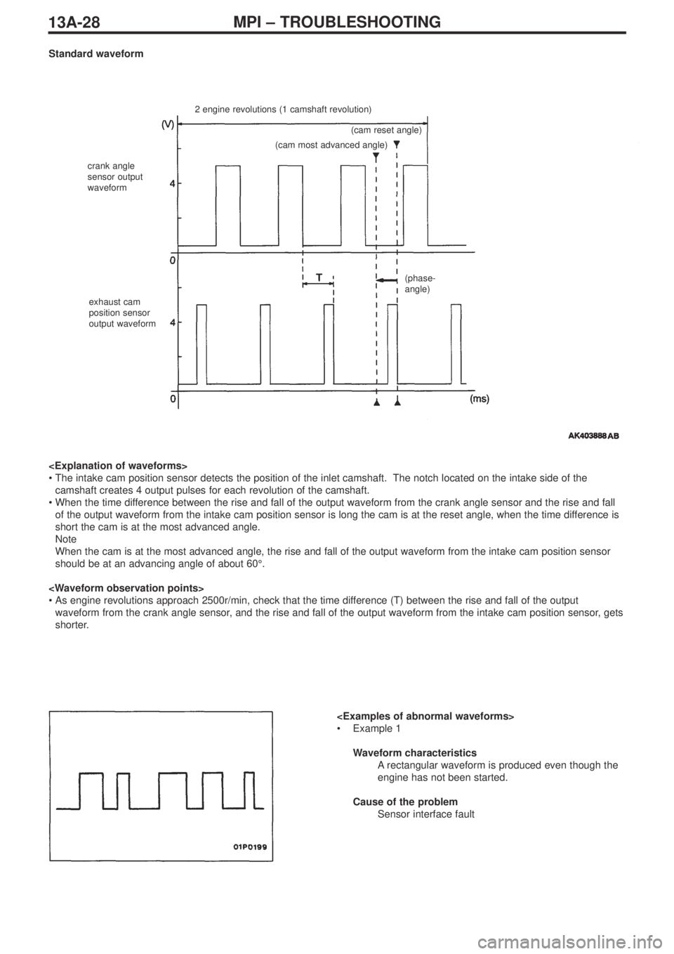
Standard waveform
2 engine revolutions (1 camshaft revolution)
crank angle
sensor output
waveform
exhaust cam
position sensor
output waveform(cam reset angle)
(cam most advanced angle)
(phase-
angle)
•The intake cam position sensor detects the position of the inlet camshaft. The notch located on the intake side of the
camshaft creates 4 output pulses for each revolution of the camshaft.
•When the time difference between the rise and fall of the output waveform from the crank angle sensor and the rise and fall
of the output waveform from the intake cam position sensor is long the cam is at the reset angle, when the time difference is
short the cam is at the most advanced angle.
Note
When the cam is at the most advanced angle, the rise and fall of the output waveform from the intake cam position sensor
should be at an advancing angle of about 60°.
•As engine revolutions approach 2500r/min, check that the time difference (T) between the rise and fall of the output
waveform from the crank angle sensor, and the rise and fall of the output waveform from the intake cam position sensor, gets
shorter.
•Example 1
Waveform characteristics
Arectangular waveform is produced even though the
engine has not been started.
Cause of the problem
Sensor interface fault
Page 69 of 364
13A-29MPI – TROUBLESHOOTING, ON-VEHICLE SERVICING
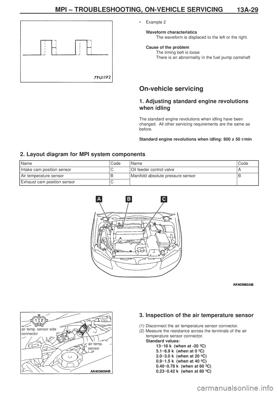
•Example 2
Waveform characteristics
The waveform is displaced to the left or the right.
Cause of the problem
The timing belt is loose
There is an abnormality in the fuel pump camshaft
On-vehicle servicing
1. Adjusting standard engine revolutions
when idling
The standard engine revolutions when idling have been
changed. All other servicing requirements are the same as
before.
Standard engine revolutions when idling: 800 ± 50 r/min
NameCodeNameCode
Intake cam position sensorCOil feeder control valveA
Air temperature sensorBManifold absolute pressure sensorB
Exhaust cam position sensorC
2. Layout diagram for MPI system components
air temp. sensor side
connector
air temp.
sensor
3. Inspection of the air temperature sensor
(1) Disconnect the air temperature sensor connector.
(2) Measure the resistance across the terminals of the air
temperature sensor connector.
Standard values:
13~18 kΩ (when at -20 ºC)
5.1~6.9 kΩ (when at 0 ºC)
2.0~3.0 kΩ (when at 20 ºC)
0.9~1.5 kΩ (when at 40 ºC)
0.40~0.78 kΩ (when at 60 ºC)
0.23~0.42 kΩ (when at 80 ºC)
Page 70 of 364
MPI – ON-VEHICLE SERVICING13A-30
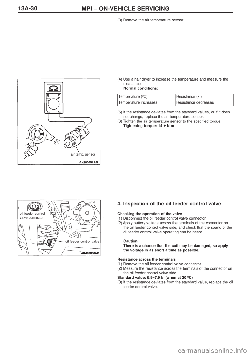
(3) Remove the air temperature sensor
(4) Use a hair dryer to increase the temperature and measure the
resistance.
Normal conditions:
air temp. sensor
Temperature (ºC)Resistance (kΩ)
Temperature increasesResistance decreases
(5) If the resistance deviates from the standard values, or if it does
not change, replace the air temperature sensor.
(6) Tighten the air temperature sensor to the specified torque.
Tightening torque: 14 ± N·m
4. Inspection of the oil feeder control valve
Checking the operation of the valve
(1) Disconnect the oil feeder control valve connector.
(2) Apply battery voltage across the terminals of the connector on
the oil feeder control valve side, and check that the sound of the
oil feeder control valve operating can be heard.
Caution
There is a chance that the coil may be damaged, so apply
the voltage in as short a time as possible.
Resistance across the terminals
(1) Remove the oil feeder control valve connector.
(2) Measure the resistance across the terminals of the connector on
the oil feeder control valve side.
Standard value: 6.9~7.9 kΩ (when at 20 ºC)
(3) If the resistance deviates from the standard value, replace the oil
feeder control valve.oil feeder control
valve connector
oil feeder control valve
Page 73 of 364
ENGINE COOLING – WATER HOSE AND PIPE
14-3
Water hose and pipe
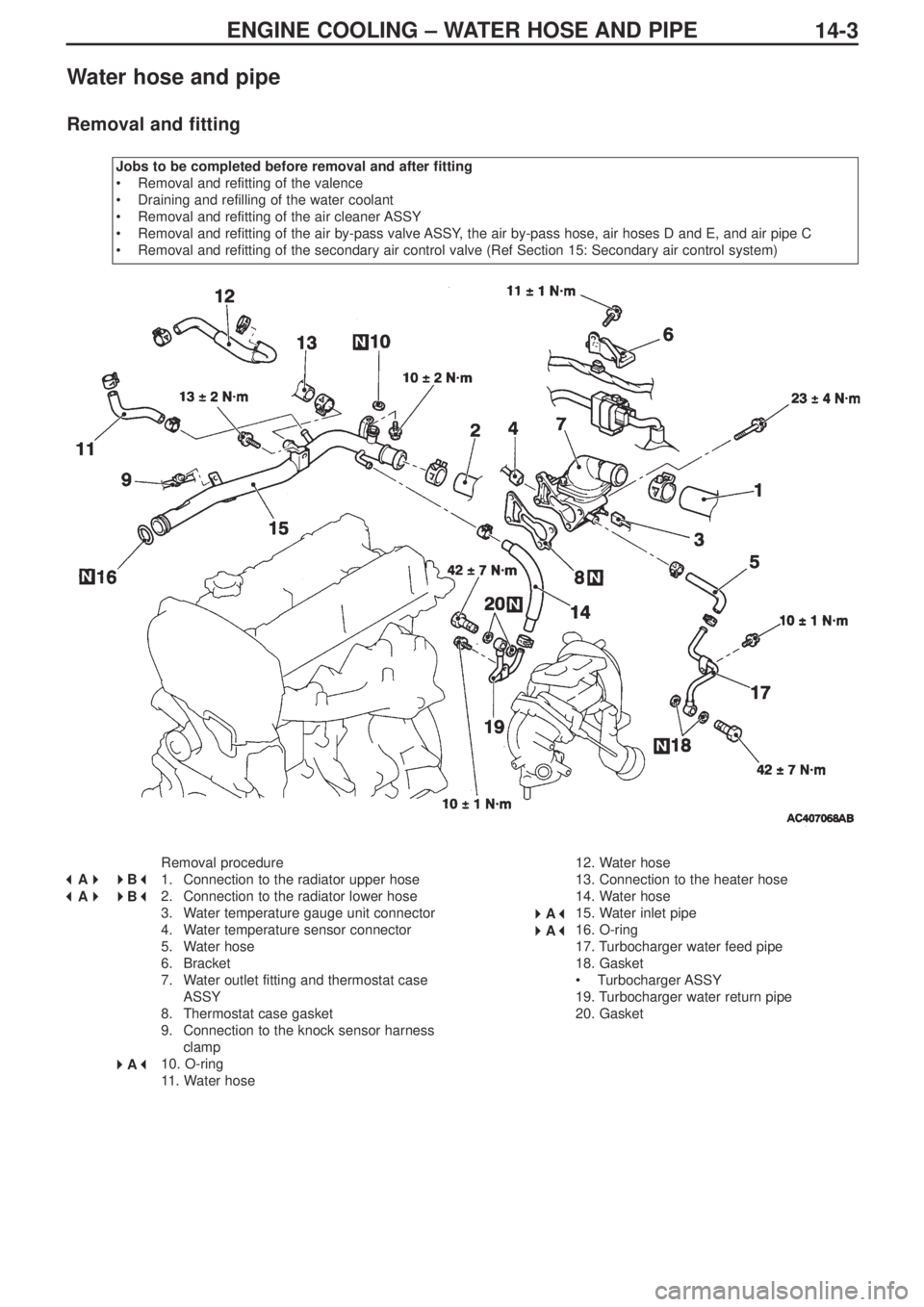
Removal and fitting
Jobs to be completed before removal and after fitting
•Removal and refitting of the valence
•Draining and refilling of the water coolant
•Removal and refitting of the air cleaner ASSY
•Removal and refitting of the air by-pass valve ASSY, the air by-pass hose, air hoses D and E, and air pipe C
•Removal and refitting of the secondary air control valve (Ref Section 15: Secondary air control system)
Removal procedure
1. Connection to the radiator upper hose
2. Connection to the radiator lower hose
3. Water temperature gauge unit connector
4. Water temperature sensor connector
5. Water hose
6. Bracket
7. Water outlet fitting and thermostat case
ASSY
8. Thermostat case gasket
9. Connection to the knock sensor harness
clamp
10. O-ring
11. Water hose12. Water hose
13. Connection to the heater hose
14. Water hose
15. Water inlet pipe
16. O-ring
17. Turbocharger water feed pipe
18. Gasket
•Turbocharger ASSY
19. Turbocharger water return pipe
20. Gasket
� �
A� �
�
�
B� �
� �
A� �
�
�
B� �
� �
A� �
�
�
A� �
� �
A� �
Page 75 of 364
INTAKE & EXHAUST – GENERAL, SERVICING STANDARDS, SPECIAL TOOLS,
ON-VEHICLE SERVICING15-1
SECTION 15
INTAKE & EXHAUST
CONTENTS
General................................................................................1
Servicing standards ..........................................................1
Special tools.......................................................................1
On-vehicle servicing..........................................................1
Turbocharger super charging pressure check ...............1Inter-cooler water spray ....................................................2
Secondary air control system ..........................................4
Inlet manifold .....................................................................5
Exhaust manifold and turbocharger ................................8
General
The following servicing guidelines have been prepared for vehicles which use the 4G63-MIVEC-T/C engine. Other servicing
guidelines remain unchanged.
• Changes to the turbocharger supercharging pressure
• Changes to the inter-cooler water spray hose
• Changes to the secondary air control valve
• Changes to the inlet manifold
• Changes to the exhaust manifold and the turbocharger
Special tools
On-vehicle servicing
Turbocharger supercharging pressure check
The standard value for the turbocharger charging pressure has
been changed. Other servicing guidelines remain unchanged.
Standard value: 97 ~ 157 kPa
ItemStandard value
Turbocharger charging pressure kPa97~157
Servicing standards
ToolNumberNameFunction
MD998770O
2sensor wrenchRemoval and fitting of the O
2
sensor