Page 21 of 364
ENGINE – CYLINDER HEAD GASKET
11-15
Removal procedure
1. Ignition coil connector
2. O
2sensor connector
3. Oil feeder control valve connector
4. Crank angle sensor connector
5. Manifold absolute pressure sensor
connector
6. Fuel pressure solenoid valve connector
7. Knock sensor connector
8. Purge control solenoid valve connector
9. Throttle position sensor connector
10. Injector connector
11.Exhaust camshaft position sensor
connector12. Inlet camshaft position sensor
connector
13. Water temperature gauge unit
connector
14. Joint control harness and transmission
harness
15. Water temperature sensor connector
16. Secondary air control solenoid valve
connector
17. Vacuum tank, solenoid valve, vacuum
pipe and hose assembly
18. Brake booster vacuum hose connection
19. Oil level gauge and guide assembly
20. O-ring
21. Purge hose connection
(engine oil)
Page 35 of 364
ENGINE – ENGINE ASSY
11-29
Removal procedure
1. Ignition coil connector
2. O
2sensor connector
3. Oil feeder control valve connector
4. Crank angle sensor connector
5. Manifold absolute pressure sensor
connector
6. Fuel pressure solenoid valve connector
7. Knock sensor connector
8. Purge control solenoid valve connector
9. Throttle position connector
10. Injector connector11.Exhaust cam position sensor connector
12. Inlet cam position sensor connector
13. Water temperature gauge unit connector
14. Joint control harness and transmission
harness
15. Water temperature sensor connector
16. Alternator connector and terminal
17. Secondary air control solenoid valve
connector
18. Engine oil pressure switch connector
19. Drive belt
� �
A� �
Page 41 of 364

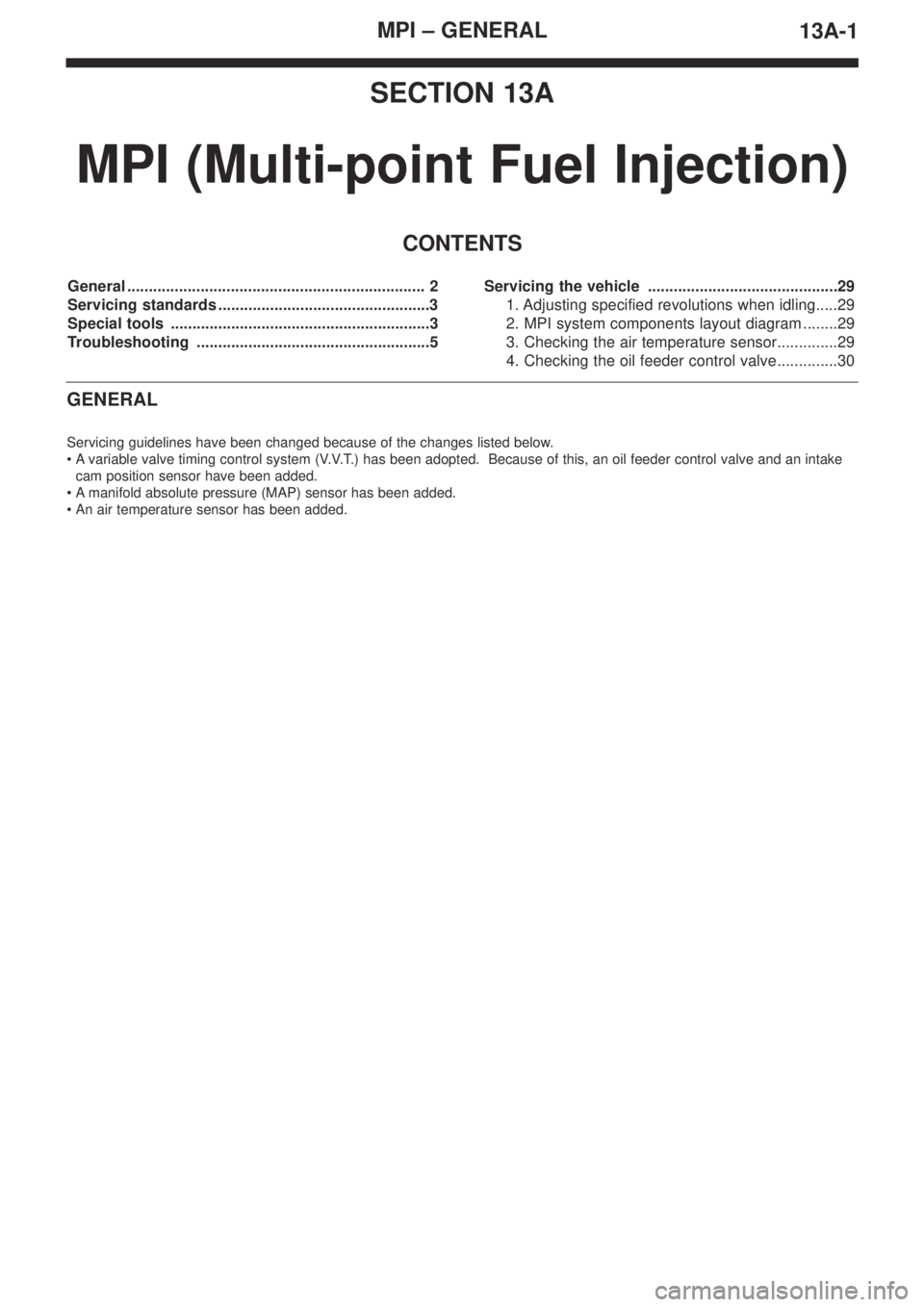
MPI – GENERAL
13A-1
SECTION 13A
MPI (Multi-point Fuel Injection)
CONTENTS
General ..................................................................... 2
Servicing standards .................................................3
Special tools ............................................................3
Troubleshooting ......................................................5Servicing the vehicle ............................................29
1. Adjusting specified revolutions when idling.....29
2. MPI system components layout diagram ........29
3. Checking the air temperature sensor..............29
4. Checking the oil feeder control valve..............30
GENERAL
Servicing guidelines have been changed because of the changes listed below.
•Avariable valve timing control system (V.V.T.) has been adopted. Because of this, an oil feeder control valve and an intake
cam position sensor have been added.
•Amanifold absolute pressure (MAP) sensor has been added.
•An air temperature sensor has been added.
Page 42 of 364

MPI – GENERAL13A-2
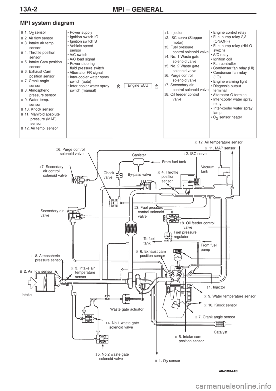
MPI system diagram
Engine ECU
H1. O
2 sensor
H2. Air flow sensor
H3. Intake air temp.
sensor
H4. Throttle position
sensor
H5. Intake Cam position
sensor
H6. Exhaust Cam
position sensor
H7. Crank angle
sensor
H8. Atmospheric
pressure sensor
H9. Water temp.
sensor
H10. Knock sensor
H11. Manifold absolute
pressure (MAP)
sensor
H12. Air temp. sensor• Power supply
• Ignition switch IG
• Ignition switch ST
• Vehicle speed
sensor
• A/C switch
• A/C load signal
• Power steering
fluid pressure switch
• Alternator FR signal
• Inter-cooler water spray
switch (auto)
•Inter-cooler water spray
switch (manual)I1. Injector
I2. ISC servo (Stepper
motor)
I3. Fuel pressure
control solenoid valve
I4. No. 1 Waste gate
solenoid valve
I5. No. 2 Waste gate
solenoid valve
I6. Purge control
solenoid valve
I7. Secondary air
control solenoid valve
I8. Oil feeder control
valve• Engine control relay
• Fuel pump relay 2,3
(ON/OFF)
• Fuel pump relay (HI/LO
switch)
• A/C relay
• Ignition coil
• Fan controller
• Condenser fan relay (HI)
• Condenser fan relay
(LO)
• Engine warning light
• Diagnosis output
terminal
• Alternator G terminal
• Inter-cooler water spray
relay
•Inter-cooler water spray
lamp
• O
2sensor heater
ÈÈ
I 6. Purge control
solenoid valve
I 7. Secondary
air control
solenoid valveCheck
valve
Secondary air
valve
To fuel
tank
H 6. Exhaust cam
position sensor
H 8. Atmospheric
pressure sensor
H 2. Air flow sensor
Intake
Waste gate actuator
I 4. No.1 waste gate
solenoid valve H 3. Intake air
temperature
sensor
I 5. No.2 waste gate
solenoid valve
H 1. O
2sensor
H 5. Intake cam
position sensorCatalyst
H 7. Crank angle sensor
H 10. Knock sensor
H 9. Water temperature sensor
I 1. Injector From fuel
pump
Fuel pressure
regulatorI 8. Oil feeder control
valve I 3. Fuel pressure
control solenoid
valve
Vacuum
tank
I 2. ISC servoH 11. MAP sensor
H 12. Air temperature sensor
H 4. Throttle
position
sensor
From fuel tank
Canister
By-pass valve
Page 45 of 364

MPI – TROUBLESHOOTING
13A-5
TROUBLESHOOTING
1. Diagnosis Functions
1-1 Engine warning light (Check engine lamp)
Changes have been made to engine warning lights.
Checklist for engine warning lights.
1-2 Checking of freeze frame data
Additions have been made to the freeze frame data tables.
Checklist for data tables
1-3 Failsafe and back-up functions
If one of the diagnosis functions detects that one of the main sensors is malfunctioning, it will ensure that the car can be driven
safely, in accordance with the pre-set control logic.
Engine ECU
Air flow sensor (AFS)
Manifold absolute pressure (MAP) sensor system
Intake air temperature sensor
Throttle position sensor (TPS)
Water temperature sensor
Crank angle sensor
Exhaust cam position sensor
Injector
Ignition coil (with built-in power transistor)
Atmospheric pressure sensor
O
2sensor
O
2sensor heater
Fuel system malfunction
Knock sensor
Intake cam position sensor system
Oil feeder control valve system
Item numberType of data Units/condition
95MAP sensorkPa
Malfunctioning itemControl measures taken when a malfunction occurs
Air temperature sensorRegulation of the intake air temperature at 25ºC.
Exhaust cam position sensor(1) Simultaneous flushing out of all fuel pipes.
(But only if the No. 1 cylinder has not been detected in the
TDC position after the ignition switch has been turned "ON".)
(2) Cutting off the fuel 4 seconds after the malfunction has been
detected.
(But only if the No. 1 cylinder has not been detected in the
TDC position after the ignition switch has been turned "ON".)
Intake cam position sensorThe oil feeder control valve should be switched "OFF", and the
angle of the cam should be in the reset position.
Page 69 of 364

13A-29MPI – TROUBLESHOOTING, ON-VEHICLE SERVICING
•Example 2
Waveform characteristics
The waveform is displaced to the left or the right.
Cause of the problem
The timing belt is loose
There is an abnormality in the fuel pump camshaft
On-vehicle servicing
1. Adjusting standard engine revolutions
when idling
The standard engine revolutions when idling have been
changed. All other servicing requirements are the same as
before.
Standard engine revolutions when idling: 800 ± 50 r/min
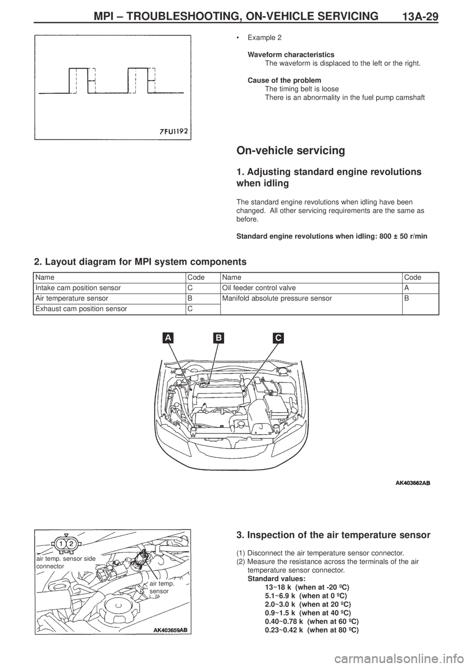
NameCodeNameCode
Intake cam position sensorCOil feeder control valveA
Air temperature sensorBManifold absolute pressure sensorB
Exhaust cam position sensorC
2. Layout diagram for MPI system components
air temp. sensor side
connector
air temp.
sensor
3. Inspection of the air temperature sensor
(1) Disconnect the air temperature sensor connector.
(2) Measure the resistance across the terminals of the air
temperature sensor connector.
Standard values:
13~18 kΩ (when at -20 ºC)
5.1~6.9 kΩ (when at 0 ºC)
2.0~3.0 kΩ (when at 20 ºC)
0.9~1.5 kΩ (when at 40 ºC)
0.40~0.78 kΩ (when at 60 ºC)
0.23~0.42 kΩ (when at 80 ºC)
Page 72 of 364
ENGINE COOLING – WATER PUMP14-2
Water pump
Removal and fitting
Jobs to be completed before removal and after fitting
•Draining and refilling of the coolant
•Removal and refitting of the timing belt (Ref Section 11)
Removal procedure
1. Alternator bracket
2. Water pump
3. Water pump gasket
4. O-ring
Fitting guidelines
� �
A� �
Fitting the O-ring
Fit the O-ring into the O-ring groove at the end of the water inlet
pipe, and insert it into the water pump after moistening with water
the places where the O-ring will make contact with the water pump.
Caution
Ensure that absolutely no engine oil, or other type of grease,
gets onto the O-ring.
Positions for fitting different sized bolts
Nominal diameter and nominal length (mm)
� �
A� �
water pump
O-ring
water inlet pipe
Page 74 of 364

ENGINE COOLING – WATER HOSE AND PIPE14-4
Removal guidelines
� �
A� �
Removing the radiator upper hose and the radiator
lower hose
Mark the radiator hose and the hose clamp with indicator marks
and then remove the radiator hose.
Fitting guidelines
� �
A� �
Fitting the O-ring and the water inlet pipe
Fit the O-ring into the groove at the end of the water inlet pipe, and
insert it after moistening with water the places where the O-ring and
the water inlet pipe will be in contact.
Caution
Ensure that absolutely no engine oil, or other type of grease,
gets onto the O-ring.
� �
B� �
Connecting the radiator lower hose and the radiator
upper hose
1. Insert the hose as far as the protrusion on the water inlet pipe
and the water outlet fitting.
2. Match up the indicator marks on the radiator hose and the hose
clamp, and fit the radiator hose.
indicator marks
water pump and
thermostat case
O-ring
water inlet pipe
protrusion
water inlet pipe and
water outlet pipe fittingindicator marks