2005 MITSUBISHI 380 Start system
[x] Cancel search: Start systemPage 1345 of 1500
AUTO-CRUISE CONTROL
ENGINE AND EMISSION CONTROL17-14
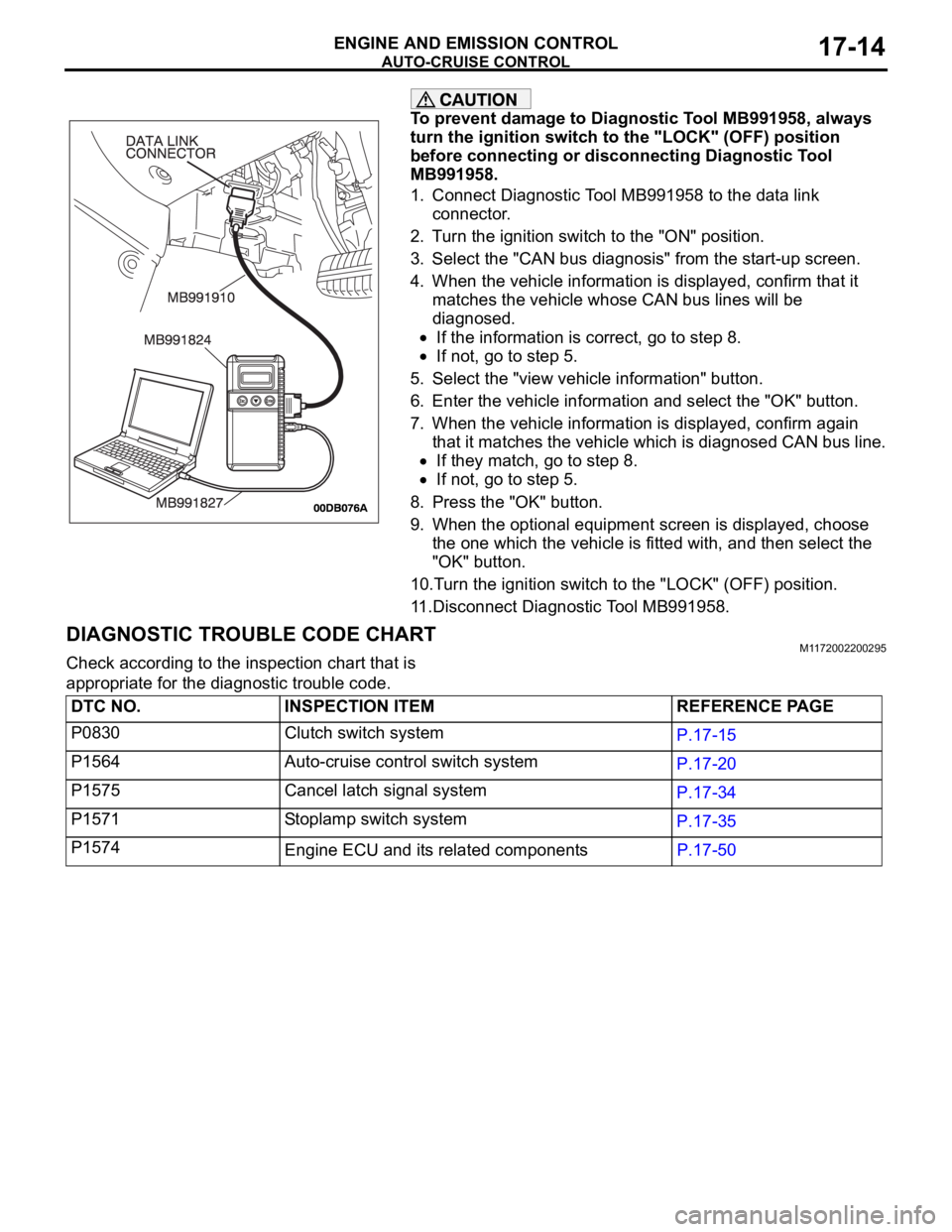
To prevent damage to Diagnostic Tool MB991958, always
turn the ignition switch to the "LOCK" (OFF) position
before connecting or disconnecting Diagnostic Tool
MB991958.
1. Connect Diagnostic Tool MB991958 to the data link
connector.
2. Turn the ignition switch to the "ON" position.
3. Select the "CAN bus diagnosis" from the start-up screen.
4. When the vehicle information is displayed, confirm that it
matches the vehicle whose CAN bus lines will be
diagnosed.
If the information is correct, go to step 8.
If not, go to step 5.
5. Select the "view vehicle information" button.
6. Enter the vehicle information and select the "OK" button.
7. When the vehicle information is displayed, confirm again
that it matches the vehicle which is diagnosed CAN bus line.
If they match, go to step 8.
If not, go to step 5.
8. Press the "OK" button.
9. When the optional equipment screen is displayed, choose
the one which the vehicle is fitted with, and then select the
"OK" button.
10.Turn the ignition switch to the "LOCK" (OFF) position.
11.Disconnect Diagnostic Tool MB991958.
DIAGNOSTIC TROUBLE CODE CHARTM1172002200295
Check according to the inspection chart that is
appropriate for the diagnostic trouble code.
DTC NO. INSPECTION ITEM REFERENCE PAGE
P0830 Clutch switch system
P.17-15
P1564 Auto-cruise control switch system
P.17-20
P1575 Cancel latch signal system
P.17-34
P1571 Stoplamp switch system
P.17-35
P1574
Engine ECU and its related componentsP.17-50
Page 1407 of 1500

EMISSION CONTROL
ENGINE AND EMISSION CONTROL17-76
EMISSION CONTROL
GENERAL DESCRIPTIONM1173000100314
The emission control system consists of the fol-
lowing subsystems:
Positive crankcase ventilation system
Evaporative emission system
Exhaust emission control system
DIAGNOSISM1173000700112
SPECIAL TOOLSM1173000600193
SYMPTOM PROBABLE CAUSE REMEDY
Engine will not start or hard
to startVacuum hose disconnected or damaged Repair or replace
Malfunction of the evaporative emission
purge solenoidRepair or replace
Rough idle or engine stalls
Vacuum hose disconnected or damaged. Repair or replace
Malfunction of the positive crankcase
ventilation valveReplace
Malfunction of the purge control system Check the system; If there is a
problem, check its component
parts.
Excessive oil consumption Positive crankcase ventilation line
cloggedCheck positive crankcase
ventilation system
TOOL TOOL NUMBER AND
NAMESUPERSESSION APPLICATION
MB995061
Purge flow indicatorMLR6890A
Part of MIT280220Inspection of purge
control system
MD998770
Oxygen sensor wrenchMD998770-01 or General
service toolRemoval/installation of
heated oxygen sensor
Page 1466 of 1500
GENERAL DESCRIPTION
AUTOMATIC TRANSMISSION23A-7
ELECTRONICALLY-CONTROLLED SYSTEM
.
INVECS-II
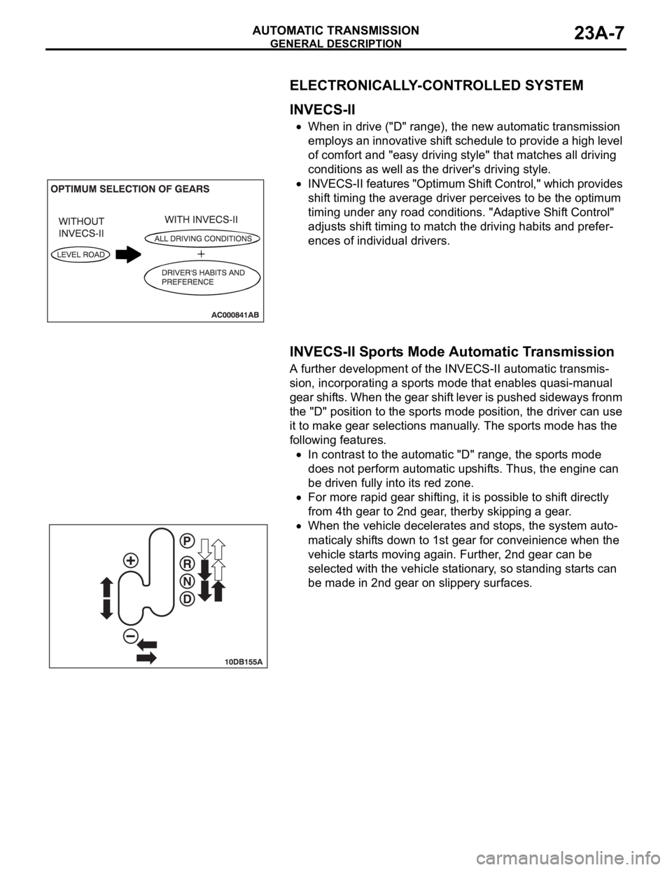
When in drive ("D" range), the new automatic transmission
employs an innovative shift schedule to provide a high level
of comfort and "easy driving style" that matches all driving
conditions as well as the driver's driving style.
INVECS-II features "Optimum Shift Control," which provides
shift timing the average driver perceives to be the optimum
timing under any road conditions. "Adaptive Shift Control"
adjusts shift timing to match the driving habits and prefer-
ences of individual drivers.
.
INVECS-II Sports Mode Automatic Transmission
A further development of the INVECS-II automatic transmis-
sion, incorporating a sports mode that enables quasi-manual
gear shifts. When the gear shift lever is pushed sideways fronm
the "D" position to the sports mode position, the driver can use
it to make gear selections manually. The sports mode has the
following features.
In contrast to the automatic "D" range, the sports mode
does not perform automatic upshifts. Thus, the engine can
be driven fully into its red zone.
For more rapid gear shifting, it is possible to shift directly
from 4th gear to 2nd gear, therby skipping a gear.
When the vehicle decelerates and stops, the system auto-
maticaly shifts down to 1st gear for conveinience when the
vehicle starts moving again. Further, 2nd gear can be
selected with the vehicle stationary, so standing starts can
be made in 2nd gear on slippery surfaces.
.
Page 1473 of 1500
AUTOMATIC TRANSMISSION DIAGNOSIS
AUTOMATIC TRANSMISSION23A-14
NOTE: If a sensor is disconnected when the ignition
switch is in the "ON" position, a diagnostic trouble
code is stored in memory. In this case, erase the
DTC using diagnostic tool.The diagnostic items are displayed in numeric order.
HOW TO CONNECT THE DIAGNOSTIC TOOL
(MUT-III)
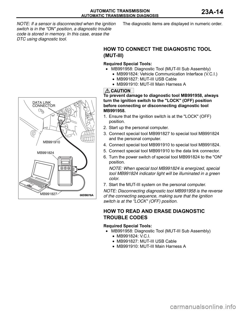
Required Special Tools:
MB991958: Diagnostic Tool (MUT-III Sub Assembly)
MB991824: Vehicle Communication Interface (V.C.I.)
MB991827: MUT-III USB Cable
MB991910: MUT-III Main Harness A
To prevent damage to diagnostic tool MB991958, always
turn the ignition switch to the "LOCK" (OFF) position
before connecting or disconnecting diagnostic tool
MB991958.
1. Ensure that the ignition switch is at the "LOCK" (OFF)
position.
2. Start up the personal computer.
3. Connect special tool MB991827 to special tool MB991824
and the personal computer.
4. Connect special tool MB991910 to special tool MB991824.
5. Connect special tool MB991910 to the data link connector.
6. Turn the power switch of special tool MB991824 to the "ON"
position.
NOTE: When special tool MB991824 is energized, special
tool MB991824 indicator light will be illuminated in a green
color.
7. Start the MUT-III system on the personal computer.
NOTE: Disconnecting diagnostic tool MB991958 is the reverse
of the connecting sequence, making sure that the ignition
switch is at the "LOCK" (OFF) position.
HOW TO READ AND ERASE DIAGNOSTIC
TROUBLE CODES
Required Special Tools:
MB991958: Diagnostic Tool (MUT-III Sub Assembly)
MB991824: V.C.I.
MB991827: MUT-III USB Cable
MB991910: MUT-III Main Harness A
Page 1474 of 1500
AUTOMATIC TRANSMISSION DIAGNOSIS
AUTOMATIC TRANSMISSION23A-15
To prevent damage to diagnostic tool MB991958, always
turn the ignition switch to the "LOCK" (OFF) position
before connecting or disconnecting diagnostic tool
MB991958.
NOTE: If the battery voltage is low, diagnostic trouble codes
will not be set. Check the battery if diagnostic tool
MB991958 does not display.
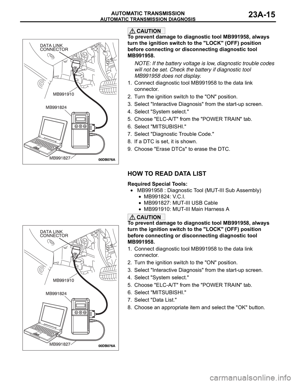
1. Connect diagnostic tool MB991958 to the data link
connector.
2. Turn the ignition switch to the "ON" position.
3. Select "Interactive Diagnosis" from the start-up screen.
4. Select "System select."
5. Choose "ELC-A/T" from the "POWER TRAIN" tab.
6. Select "MITSUBISHI."
7. Select "Diagnostic Trouble Code."
8. If a DTC is set, it is shown.
9. Choose "Erase DTCs" to erase the DTC.
HOW TO READ DATA LIST
Required Special Tools:
MB991958 : Diagnostic Tool (MUT-III Sub Assembly)
MB991824: V.C.I.
MB991827: MUT-III USB Cable
MB991910: MUT-III Main Harness A
To prevent damage to diagnostic tool MB991958, always
turn the ignition switch to the "LOCK" (OFF) position
before connecting or disconnecting diagnostic tool
MB991958.
1. Connect diagnostic tool MB991958 to the data link
connector.
2. Turn the ignition switch to the "ON" position.
3. Select "Interactive Diagnosis" from the start-up screen.
4. Select "System select."
5. Choose "ELC-A/T" from the "POWER TRAIN" tab.
6. Select "MITSUBISHI."
7. Select "Data List."
8. Choose an appropriate item and select the "OK" button.
Page 1475 of 1500
AUTOMATIC TRANSMISSION DIAGNOSIS
AUTOMATIC TRANSMISSION23A-16
HOW TO PERFORM ACTUATOR TEST
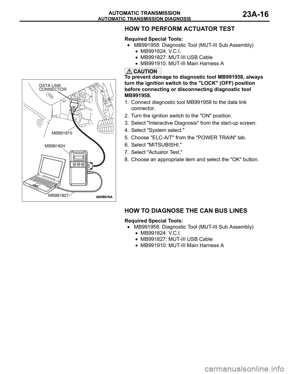
Required Special Tools:
MB991958: Diagnostic Tool (MUT-III Sub Assembly)
MB991824: V.C.I.
MB991827: MUT-III USB Cable
MB991910: MUT-III Main Harness A
To prevent damage to diagnostic tool MB991958, always
turn the ignition switch to the "LOCK" (OFF) position
before connecting or disconnecting diagnostic tool
MB991958.
1. Connect diagnostic tool MB991958 to the data link
connector.
2. Turn the ignition switch to the "ON" position.
3. Select "Interactive Diagnosis" from the start-up screen.
4. Select "System select."
5. Choose "ELC-A/T" from the "POWER TRAIN" tab.
6. Select "MITSUBISHI."
7. Select "Actuator Test."
8. Choose an appropriate item and select the "OK" button.
HOW TO DIAGNOSE THE CAN BUS LINES
Required Special Tools:
MB991958: Diagnostic Tool (MUT-III Sub Assembly)
MB991824: V.C.I.
MB991827: MUT-III USB Cable
MB991910: MUT-III Main Harness A
Page 1476 of 1500
AUTOMATIC TRANSMISSION DIAGNOSIS
AUTOMATIC TRANSMISSION23A-17
To prevent damage to diagnostic tool MB991958, always
turn the ignition switch to the "LOCK" (OFF) position
before connecting or disconnecting diagnostic tool
MB991958.
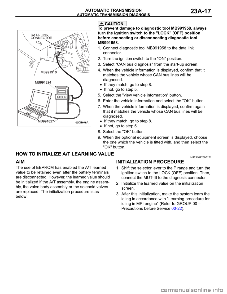
1. Connect diagnostic tool MB991958 to the data link
connector.
2. Turn the ignition switch to the "ON" position.
3. Select "CAN bus diagnosis" from the start-up screen.
4. When the vehicle information is displayed, confirm that it
matches the vehicle whose CAN bus lines will be
diagnosed.
If they match, go to step 8.
If not, go to step 5.
5. Select the "view vehicle information" button.
6. Enter the vehicle information and select the "OK" button.
7. When the vehicle information is displayed, confirm again
that it matches the vehicle whose CAN bus lines will be
diagnosed.
If they match, go to step 8.
If not, go to step 5.
8. Select the "OK" button.
9. When the optional equipment screen is displayed, choose
the one which the vehicle is fitted with, and then select the
"OK" button.
HOW TO INITIALIZE A/T LEARNING VALUEM1231022600121
AIM
The use of EEPROM has enabled the A/T learned
value to be retained even after the battery terminals
are disconnected. However, the learned value should
be initialized if the A/T assembly, the engine assem-
bly, the valve body assembly or the solenoid valves
are replaced. The initialization procedure is as
below:
INITIALIZATION PROCEDURE
1. Shift the selector lever to the P range and turn the
ignition switch to the LOCK (OFF) position. Then,
connect the MUT-III to the diagnosis connector.
2. Initialize the learned value on the initialization
screen.
3. After this initialization, make the system learn the
idling in accordance with "Learning procedure for
idling in MPI engine" (Refer to GROUP 00
Precautions before Service 00-22).
Page 1478 of 1500

AUTOMATIC TRANSMISSION DIAGNOSIS
AUTOMATIC TRANSMISSION23A-19
ROAD TESTM1231007800407
Check using the following procedures.
STEP CONDITION
BEFORE
TEST/OPERATIONTEST/OPERATION STANDARD INSPECTION
ITEMINSPECTION
PROCEDURE
PA G E
1 Ignition switch:
(LOCK) OFFIgnition switch
(1) ONData list No.8
(1) Control Relay
Voltage [V]A/T Control
relay
output
voltageA/T Control
relay system
(P.23A-207).
2 Ignition switch:
ON
Engine: Stopped
Transmission
range: PTransmission range
(1) P, (2) R, (3) N, (4)
DData list No.34
(1) P, (2) R, (3) N, (4)
DTransmissi
on range
switchTransmission
range switch
system
(P.23A-97,
P.23A-119).
Transmission range
(1) D (1st gear)
(2) Select the sport
mode (1st gear)
(3) Upshift and hold
the selector lever in
that position (2nd
gear)
(4) Downshift and
hold the selector
lever in that position
(1st gear)Data list No.27
(1) OFF, (2) ON, (3)
ON, (4) ON
Data list No.28
(1) OFF, (2) OFF, (3)
ON, (4) OFF
Data list No.29
(1) OFF, (2) OFF, (3)
OFF, (4) ONSelect
switch and
Shift switchShift switch
assembly
system
(P.23A-252).
Brake pedal
(1) Depressed
(2) ReleasedData list No.19
(1) ON
(2) OFFSto pl amp
switchSt o pla mp
switch system
(P.23A-89).
3 Ignition switch:
ST
Engine: StoppedCranking test with
lever in P or N rangeCranking should be
possibleCranking Engine does
not crank
(P.23A-218).
4 Engine warming
upDrive for 15 minutes
or more so that the
transmission fluid
temperature
becomes 70
90CData list No.7
Gradually rises to 70
90CTransmissi
on fluid
temperatur
e sensorTransmission
fluid
temperature
sensor system
(P.23A-36,
P.23A-47).
5 Engine: Idling
Transmission
range: NBrake pedal (Retest)
(1) Depressed
(2) ReleasedData list No.19
(1) ON
(2) OFFSto pl amp
switchSt o pla mp
switch system
(P.23A-89).
Transmission range
(1) N
D
(2) N
RShould be no
abnormal shift
shocks
Time delay when
engaging should be
within 2 secondsMalfunction
when
startingEngine stalls
when moving
selector lever
from N to D or
N to R
(P.23A-227).