Page 1302 of 1500

TRACTION CONTROL SYSTEM (TCL) DIAGNOSIS
TRACTION CONTROL SYSTEM (TCL)13C-23
SYMPTOM CHARTM1136003400029
SYMPTOM PROCEDURES
INSPECTION PROCEDURE 1: When the Ignition Switch is Turned to the "ON" Position
(Engine Stopped), the "TCL OFF" Indicator Light does not Illuminate. INSPECTION
PROCEDURE 2: When the Ignition Switch is Turned to the "ON" Position (Engine
Stopped), the TCL Work Indicator Light dose not Illuminate. INSPECTION
PROCEDURE 3: The "TCL OFF" Indicator Light Remains Illuminated After the Engine
is Started. INSPECTION PROCEDURE 4: The TCL Work Indicator Light Remains
Illuminated After the Engine is Started.
SYMPTOM INSPECTION
PROCEDURE NO.REFERENCE
PA G E
Communication with
diagnostic tool is not
possibleCommunication with all systems is
impossible- Group 13A, MPI
Diagnosis
Symptom
Procedures
Inspection
Procedure 1
P.13A-539.
Communication with the ABS/TCL-ECU
only is impossible- Group 35B, ABS
Diagnosis
Symptom
Procedures
Inspection
Procedure 1
P.35B-72.
When the ignition switch is turned to the "ON" position (engine
stopped), the "TCL OFF" indicator light dose not illuminate.1
P.13C-23
When the ignition switch is turned to the "ON" position (engine
stopped), the TCL work indicator light does not illuminate.2
The "TCL OFF" indicator light remains illuminated after the engine
is started.3
The TCL work indicator light remains illuminated after the engine
is started.4
When the TCL switch is push on, TCL does not be cancelled. 5
P.13C-28
TCL dose not operate. 6
P.13C-34
Page 1307 of 1500
TRACTION CONTROL SYSTEM (TCL) DIAGNOSIS
TRACTION CONTROL SYSTEM (TCL)13C-28
STEP 4. Retest the system
Q: Turn the ignition switch to the "ON" position. Do the
"TCL OFF" indicator light and the TCL work indicator
light illuminate for three seconds, and then go out after
the engine starts?
YES : The procedure is complete.
NO : . Return to Step 1.
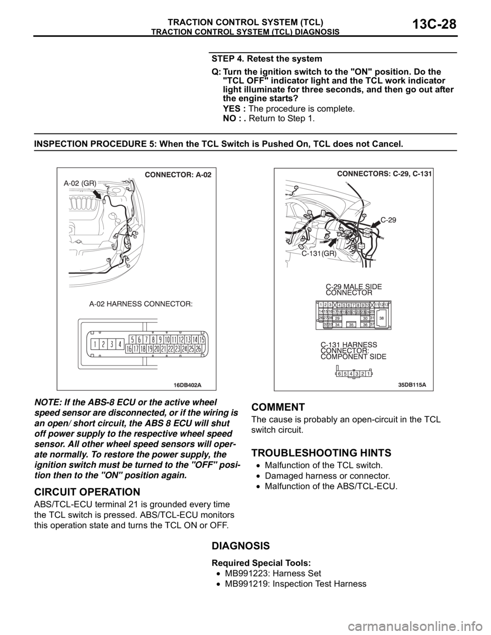
INSPECTION PROCEDURE 5: When the TCL Switch is Pushed On, TCL does not Cancel.
NOTE: If the ABS-8 ECU or the active wheel
speed sensor are disconnected, or if the wiring is
an open/ short circuit, the ABS 8 ECU will shut
off power supply to the respective wheel speed
sensor. All other wheel speed sensors will oper-
ate normally. To restore the power supply, the
ignition switch must be turned to the "OFF" posi-
tion then to the "ON" position again.
.
CIRCUIT OPERATION
ABS/TCL-ECU terminal 21 is grounded every time
the TCL switch is pressed. ABS/TCL-ECU monitors
this operation state and turns the TCL ON or OFF.
.
COMMENT
The cause is probably an open-circuit in the TCL
switch circuit.
.
TROUBLESHOOTING HINTS
Malfunction of the TCL switch.
Damaged harness or connector.
Malfunction of the ABS/TCL-ECU.
DIAGNOSIS
Required Special Tools:
MB991223: Harness Set
MB991219: Inspection Test Harness
Page 1317 of 1500
TRACTION CONTROL SYSTEM (TCL) DIAGNOSIS
TRACTION CONTROL SYSTEM (TCL)13C-38
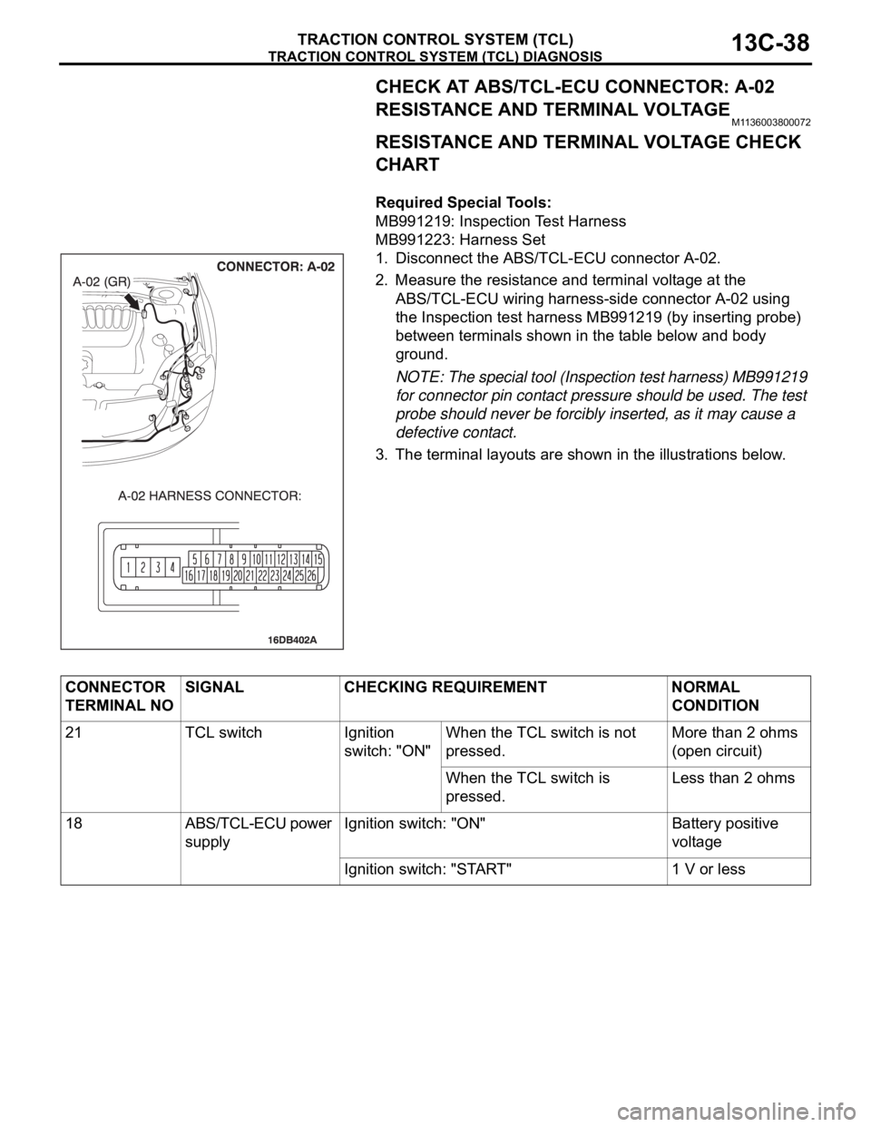
CHECK AT ABS/TCL-ECU CONNECTOR: A-02
RESISTANCE AND TERMINAL VOLTAGE
M1136003800072
RESISTANCE AND TERMINAL VOLTAGE CHECK
CHART
.
Required Special Tools:
MB991219: Inspection Test Harness
MB991223: Harness Set
1. Disconnect the ABS/TCL-ECU connector A-02.
2. Measure the resistance and terminal voltage at the
ABS/TCL-ECU wiring harness-side connector A-02 using
the Inspection test harness MB991219 (by inserting probe)
between terminals shown in the table below and body
ground.
NOTE: The special tool (Inspection test harness) MB991219
for connector pin contact pressure should be used. The test
probe should never be forcibly inserted, as it may cause a
defective contact.
3. The terminal layouts are shown in the illustrations below.
CONNECTOR
TERMINAL NOSIGNAL CHECKING REQUIREMENT NORMAL
CONDITION
21 TCL switch Ignition
switch: "ON" When the TCL switch is not
pressed.More than 2 ohms
(open circuit)
When the TCL switch is
pressed.Less than 2 ohms
18 ABS/TCL-ECU power
supplyIgnition switch: "ON" Battery positive
voltage
Ignition switch: "START" 1 V or less
Page 1326 of 1500
ON-VEHICLE SERVICE
TRACTION CONTROL SYSTEM (TCL)13C-47
ON-VEHICLE SERVICE
TCL INDICATOR LIGHT CHECKM1136000900058
1. Check that the "TCL OFF" indicator light and the TCL work
indicator light illuminate for three seconds when the ignition
switch is turned to the "ON" position.
2. Check that the "TCL OFF" indicator light illuminates and
goes off in cycles each time the TCL switch is pushed after
starting the engine.
3. Check that the "TCL OFF" indicator light and the TCL work
indicator light do not illuminate, when driving at 30km/h
(37.5 mph) for more than 2 seconds.
4. If defective, repair it. (Refer to P.13C-23, TCL diagnosis
Symptom Procedures
Inspection Procedure 1, 2, 3 and 4).
TCL OPERATION CHECKM1136001100055
Required Special Tools:
MB991958: Diagnostic Tool (MUT-III Sub Assembly)
MB991824: V.C.I.
MB991827: MUT-III USB Cable
MB991910: MUT-III Main Harness A
Page 1336 of 1500
ENGINE CONTROL
ENGINE AND EMISSION CONTROL17-5
DIAGNOSIS
Required Special Tools:
MB991958: Diagnostic Tool (MUT-III Sub Assembly)
MB991824: Vehicle Communication Interface (V.C.I.)
MB991827: MUT-III USB Cable
MB991910: MUT-III Main Harness A
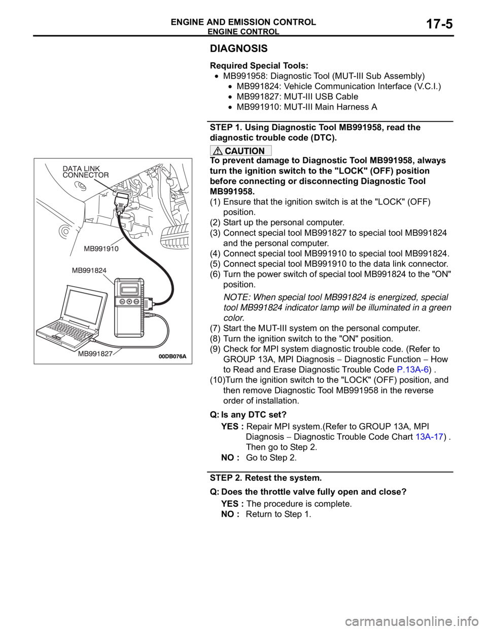
STEP 1. Using Diagnostic Tool MB991958, read the
diagnostic trouble code (DTC).
To prevent damage to Diagnostic Tool MB991958, always
turn the ignition switch to the "LOCK" (OFF) position
before connecting or disconnecting Diagnostic Tool
MB991958.
(1) Ensure that the ignition switch is at the "LOCK" (OFF)
position.
(2) Start up the personal computer.
(3) Connect special tool MB991827 to special tool MB991824
and the personal computer.
(4) Connect special tool MB991910 to special tool MB991824.
(5) Connect special tool MB991910 to the data link connector.
(6) Turn the power switch of special tool MB991824 to the "ON"
position.
NOTE: When special tool MB991824 is energized, special
tool MB991824 indicator lamp will be illuminated in a green
color.
(7) Start the MUT-III system on the personal computer.
(8) Turn the ignition switch to the "ON" position.
(9) Check for MPI system diagnostic trouble code. (Refer to
GROUP 13A, MPI Diagnosis
Diagnostic Function How
to Read and Erase Diagnostic Trouble Code P.13A-6) .
(10)Turn the ignition switch to the "LOCK" (OFF) position, and
then remove Diagnostic Tool MB991958 in the reverse
order of installation.
Q: Is any DTC set?
YES : Repair MPI system.(Refer to GROUP 13A, MPI
Diagnosis
Diagnostic Trouble Code Chart 13A-17) .
Then go to Step 2.
NO : Go to Step 2.
STEP 2. Retest the system.
Q: Does the throttle valve fully open and close?
YES : The procedure is complete.
NO : Return to Step 1.
Page 1338 of 1500
ENGINE CONTROL
ENGINE AND EMISSION CONTROL17-7
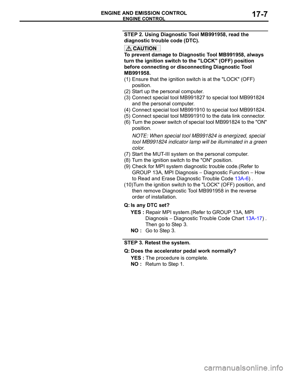
STEP 2. Using Diagnostic Tool MB991958, read the
diagnostic trouble code (DTC).
To prevent damage to Diagnostic Tool MB991958, always
turn the ignition switch to the "LOCK" (OFF) position
before connecting or disconnecting Diagnostic Tool
MB991958.
(1) Ensure that the ignition switch is at the "LOCK" (OFF)
position.
(2) Start up the personal computer.
(3) Connect special tool MB991827 to special tool MB991824
and the personal computer.
(4) Connect special tool MB991910 to special tool MB991824.
(5) Connect special tool MB991910 to the data link connector.
(6) Turn the power switch of special tool MB991824 to the "ON"
position.
NOTE: When special tool MB991824 is energized, special
tool MB991824 indicator lamp will be illuminated in a green
color.
(7) Start the MUT-III system on the personal computer.
(8) Turn the ignition switch to the "ON" position.
(9) Check for MPI system diagnostic trouble code.(Refer to
GROUP 13A, MPI Diagnosis
Diagnostic Function How
to Read and Erase Diagnostic Trouble Code 13A-6) .
(10)Turn the ignition switch to the "LOCK" (OFF) position, and
then remove Diagnostic Tool MB991958 in the reverse
order of installation.
Q: Is any DTC set?
YES : Repair MPI system.(Refer to GROUP 13A, MPI
Diagnosis
Diagnostic Trouble Code Chart 13A-17) .
Then go to Step 3.
NO : Go to Step 3.
STEP 3. Retest the system.
Q: Does the accelerator pedal work normally?
YES : The procedure is complete.
NO : Return to Step 1.
Page 1343 of 1500
AUTO-CRUISE CONTROL
ENGINE AND EMISSION CONTROL17-12
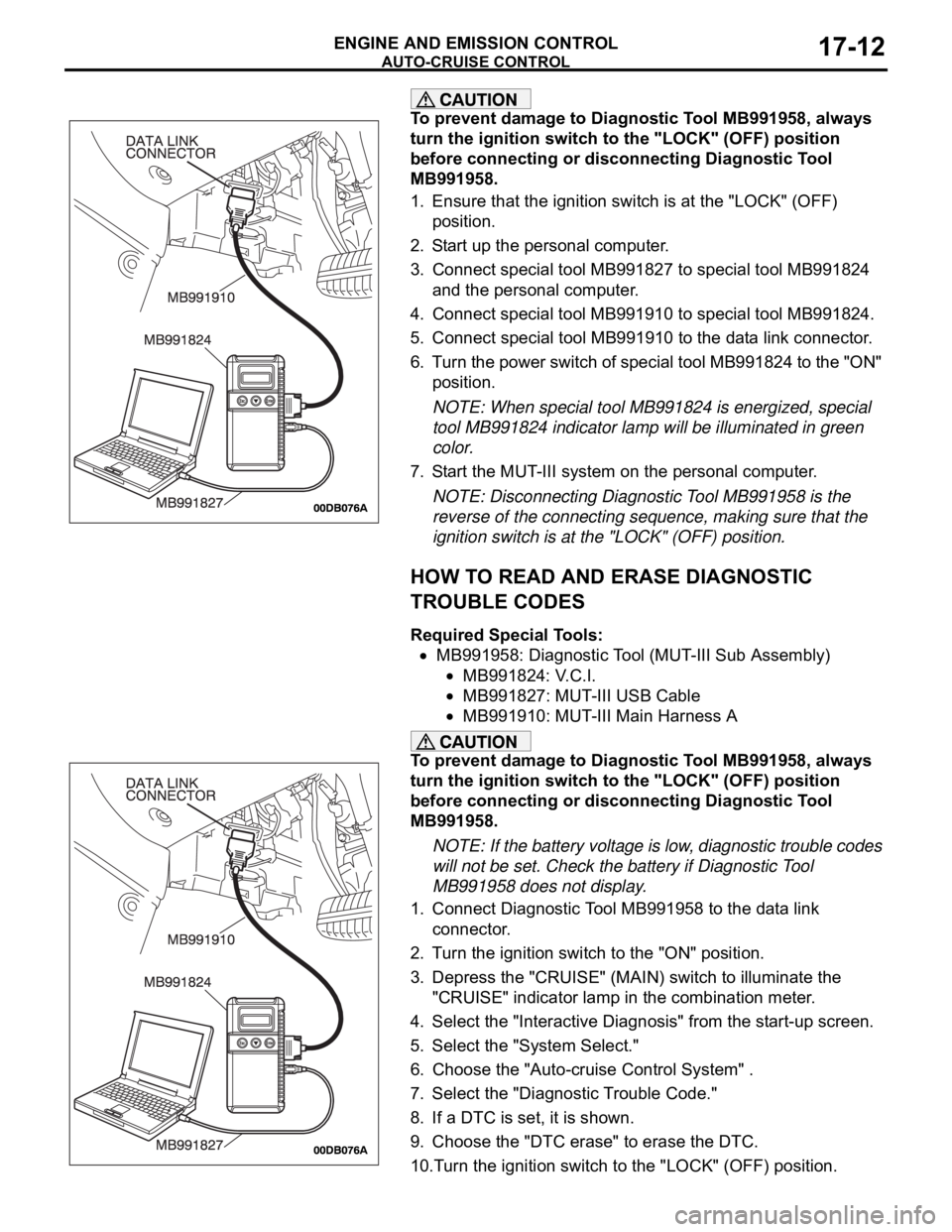
To prevent damage to Diagnostic Tool MB991958, always
turn the ignition switch to the "LOCK" (OFF) position
before connecting or disconnecting Diagnostic Tool
MB991958.
1. Ensure that the ignition switch is at the "LOCK" (OFF)
position.
2. Start up the personal computer.
3. Connect special tool MB991827 to special tool MB991824
and the personal computer.
4. Connect special tool MB991910 to special tool MB991824.
5. Connect special tool MB991910 to the data link connector.
6. Turn the power switch of special tool MB991824 to the "ON"
position.
NOTE: When special tool MB991824 is energized, special
tool MB991824 indicator lamp will be illuminated in green
color.
7. Start the MUT-III system on the personal computer.
NOTE: Disconnecting Diagnostic Tool MB991958 is the
reverse of the connecting sequence, making sure that the
ignition switch is at the "LOCK" (OFF) position.
HOW TO READ AND ERASE DIAGNOSTIC
TROUBLE CODES
Required Special Tools:
MB991958: Diagnostic Tool (MUT-III Sub Assembly)
MB991824: V.C.I.
MB991827: MUT-III USB Cable
MB991910: MUT-III Main Harness A
To prevent damage to Diagnostic Tool MB991958, always
turn the ignition switch to the "LOCK" (OFF) position
before connecting or disconnecting Diagnostic Tool
MB991958.
NOTE: If the battery voltage is low, diagnostic trouble codes
will not be set. Check the battery if Diagnostic Tool
MB991958 does not display.
1. Connect Diagnostic Tool MB991958 to the data link
connector.
2. Turn the ignition switch to the "ON" position.
3. Depress the "CRUISE" (MAIN) switch to illuminate the
"CRUISE" indicator lamp in the combination meter.
4. Select the "Interactive Diagnosis" from the start-up screen.
5. Select the "System Select."
6. Choose the "Auto-cruise Control System" .
7. Select the "Diagnostic Trouble Code."
8. If a DTC is set, it is shown.
9. Choose the "DTC erase" to erase the DTC.
10.Turn the ignition switch to the "LOCK" (OFF) position.
Page 1344 of 1500
AUTO-CRUISE CONTROL
ENGINE AND EMISSION CONTROL17-13
11.Disconnect Diagnostic Tool MB991958.
HOW TO READ DATA LIST
Required Special Tools:
MB991958: Diagnostic Tool (MUT-III Sub Assembly)
MB991824: V.C.I.
MB991827: MUT-III USB Cable
MB991910: MUT-III Main Harness A
To prevent damage to Diagnostic Tool MB991958, always
turn the ignition switch to the "LOCK" (OFF) position
before connecting or disconnecting Diagnostic Tool
MB991958.
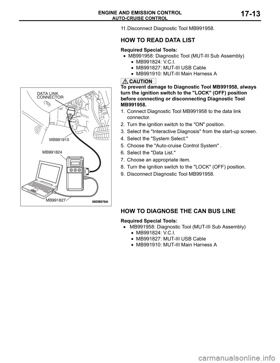
1. Connect Diagnostic Tool MB991958 to the data link
connector.
2. Turn the ignition switch to the "ON" position.
3. Select the "Interactive Diagnosis" from the start-up screen.
4. Select the "System Select."
5. Choose the "Auto-cruise Control System" .
6. Select the "Data List."
7. Choose an appropriate item.
8. Turn the ignition switch to the "LOCK" (OFF) position.
9. Disconnect Diagnostic Tool MB991958.
HOW TO DIAGNOSE THE CAN BUS LINE
Required Special Tools:
MB991958: Diagnostic Tool (MUT-III Sub Assembly)
MB991824: V.C.I.
MB991827: MUT-III USB Cable
MB991910: MUT-III Main Harness A