Page 844 of 1500

ON-VEHICLE SERVICE
HEATER, AIR CONDITIONING AND VENTILATION55-143
PERFORMANCE TEST M1552001400526
The vehicles to be tested should be parked out of direct sun-
light.
1. Close the high and low-pressure valve of the gauge
manifold.
2. Connect the charging hose (blue) to the low-pressure valve
and connect the charging hose (red) to the high-pressure
valve of the gauge manifold.
3. Install the quick joint (for low-pressure) to the charging hose
(blue), and connect the quick joint (for high-pressure) to the
charging hose (red).
To connect the quick joint, press section A firmly
against the service valve until a click is heard.
When connecting, run your hand along the hose while
pressing to ensure that there are no bends in the hose.
4. Connect the quick joint (for low-pressure) to the
low-pressure service valve and connect the quick joint (for
high-pressure) to the high-pressure service valve.
NOTE: The high-pressure service valve is on the A/C pipe
and the low-pressure service valve is on the suction hose.
5. Start the engine.
6. Set the A/C controls as follows:
A/C switch: A/C ON position
Mode selection: FACE position
Temperature control: MAXIMUM COOLING position
Air selection: RECIRCULATION position
Blower switch: Maximum air volume
7. Adjust engine speed to 1,500 r/min with A/C clutch engaged.
8. Engine should be warmed up with doors and windows
closed.
9. Insert a thermometer in the center air outlet and operate the
engine for 20 minutes.
NOTE: If the A/C clutch cycles, take the reading before the
clutch disengages.
10.Note the discharge air temperature.
PERFORMANCE TEMPERATURE CHART
GARAGE AMBIENT AIR TEMPERATURE C
(
F)20 (68) 25 (77) 30 (86) 35 (95)
Discharge air temperature
C (F) 1 (34) 6 (43)
Compressor high pressure kPa (psi) 1275 (185)
1863 (270)
Compressor low pressure kPa (psi) 49 (7.1)
294 (42.7)
Page 850 of 1500

ON-VEHICLE SERVICE
HEATER, AIR CONDITIONING AND VENTILATION55-149
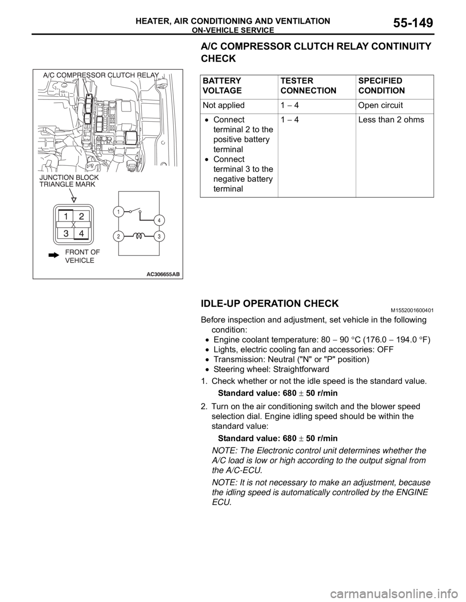
A/C COMPRESSOR CLUTCH RELAY CONTINUITY
CHECK
IDLE-UP OPERATION CHECK
M1552001600401
Before inspection and adjustment, set vehicle in the following
condition:
Engine coolant temperature: 80 90 C (176.0 194.0 F)
Lights, electric cooling fan and accessories: OFF
Transmission: Neutral ("N" or "P" position)
Steering wheel: Straightforward
1. Check whether or not the idle speed is the standard value.
Standard value: 680
50 r/min
2. Turn on the air conditioning switch and the blower speed
selection dial. Engine idling speed should be within the
standard value:
Standard value: 680
50 r/min
NOTE: The Electronic control unit determines whether the
A/C load is low or high according to the output signal from
the A/C-ECU.
NOTE: It is not necessary to make an adjustment, because
the idling speed is automatically controlled by the ENGINE
ECU. BATTERY
V O LTA G ETESTER
CONNECTIONSPECIFIED
CONDITION
Not applied 1
4 Open circuit
Connect
terminal 2 to the
positive battery
terminal
Connect
terminal 3 to the
negative battery
terminal1
4 Less than 2 ohms
Page 853 of 1500
Page 905 of 1500
HOW TO DIAGNOSE
GENERAL 00E-4
INSPECTIONM1001004600139
1. Sight and sound checks
Check relay operation, blower motor rotation, light
illumination, etc. Listen for a "click" when some relay covers
are pushed down.
2. Simple checks
For example, if a headlight does not come on and a faulty
fuse or poor grounding is suspected, replace the fuse with a
new one. Or use a jumper wire to ground the light to the
body. Determine which part(s) is/are responsible for the
problem.
3. Checking with instruments
Use an appropriate instrument in an adequate range and
read the indication correctly.
Page 906 of 1500
HOW TO DIAGNOSE
GENERAL 00E-5
INSPECTION INSTRUMENTSM1001004700040
For inspection, use the following instruments:
Never use a test light for checking ECU-related circuits or
ECUs.
1. Test light
A test light consists of a 12V bulb and lead wires. It is used
to check voltages or short circuits.
2. Self-powered test light
A self-powered test light consists of a bulb, battery and lead
wires connected in series. It is used to check continuity or
grounding.
Never use a jumper wire to connect a power supply
directly to a load.
3. Jumper wire
A jumper wire is used to close an open circuit.
4. Voltmeter
A voltmeter is used to measure the circuit voltage. Normally,
the positive (red lead) test probe is applied to the point of
voltage measurement and the negative (black lead) test
probe to the body ground. Use a digital voltmeter to check
for voltage drop before or after a component.
Page 907 of 1500

HOW TO DIAGNOSE
GENERAL 00E-6
5. Ohmmeter
An ohmmeter is used to check continuity or measure
resistance of a switch or coil. If the measuring range has
been changed, the zero point must be adjusted before
measurement.
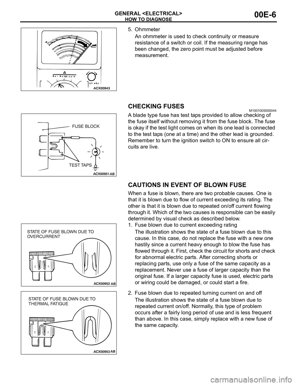
CHECKING FUSESM1001005000044
A blade type fuse has test taps provided to allow checking of
the fuse itself without removing it from the fuse block. The fuse
is okay if the test light comes on when its one lead is connected
to the test taps (one at a time) and the other lead is grounded.
Remember to turn the ignition switch to ON to ensure all cir-
cuits are live.
CAUTIONS IN EVENT OF BLOWN FUSE
When a fuse is blown, there are two probable causes. One is
that it is blown due to flow of current exceeding its rating. The
other is that it is blown due to repeated on/off current flowing
through it. Which of the two causes is responsible can be easily
determined by visual check as described below.
1. Fuse blown due to current exceeding rating
The illustration shows the state of a fuse blown due to this
cause. In this case, do not replace the fuse with a new one
hastily since a current heavy enough to blow the fuse has
flowed through it. First, check the circuit for shorts and check
for abnormal electric parts. After correcting shorts or
replacing parts, use only a fuse of the same capacity as a
replacement. Never use a fuse of larger capacity than the
original fuse. If a larger capacity fuse is used, electric parts
or wiring could be damaged, or could start a fire.
2. Fuse blown due to repeated turning current on and off
The illustration shows the state of a fuse blown due to
repeated current on/off. Normally, this type of problem
occurs after a fairly long period of use and is less frequent
than above. In this case, simply replace with a new fuse of
the same capacity.
Page 909 of 1500

HOW TO DIAGNOSE
GENERAL 00E-8
CHECKING RELAYSM1001004900152
1. By using a relay, a heavy current can be turned on and off by
a switch using much less current. For example, in the circuit
shown here, when the switch is turned on (closed), current
flows to the coil of the relay. Then, its contact is turned on
(closed) and the light comes on. The current flowing through
the switch is much less than that for the light.
2. When current flows through the coil of a relay, its core is
magnetized to attract the iron piece, closing (ON) the
contact at the tip of the iron piece. When the coil current is
turned off, the iron piece returns to its original position by a
spring, opening the contact (OFF).
3. Relays may be classified as the normally open-type or the
normally closed-type, depending on their contact
construction.
NOTE: The deenergised state means that no current is flow-
ing through the coil. The energised state means that current
is flowing through the coil.
(1) The normally open-type
When a normally open relay as illustrated here is
checked, there should be no continuity between terminals
3 and 4 when the relay is deenergised. There should be
continuity between terminals 3 and 4 when battery
voltage and ground are applied to terminals 1 and 2. The
relay condition is determined by this check.
NOTE: Check the relay in both situation which is
energised and is not energised.
(2) The normally closed-type
When a normally closed relay as illustrated here is
checked, there should be continuity between terminals 3
and 4 when the relay is deenergised. There should be no
continuity between terminals 3 and 4 when battery
voltage and ground are applied to terminals 1 and 2. The
relay condition is determined by this check.
NOTE: Check the relay in both situation which is
energised and is not energised.
Page 911 of 1500

HOW TO DIAGNOSE
GENERAL 00E-10
1. VOLTAGE CHECK
(1) Ground one lead wire of the test light. If a voltmeter is
used instead of the test light, ground the grounding side
lead wire.
(2) Connect the other lead wire of the test light to the power
side terminal of the switch connector. The test light
should come on or the voltmeter should indicate a
voltage.
(3) Then, connect the test light or voltmeter to the motor
connector. The test light should not come on, or the
voltmeter should indicate no voltage. When the switch is
turned ON in this state, the test light should come on, or
the voltmeter should indicate a voltage, with the motor
starting to run.
(4) The circuit illustrated here is normal. If there is any
problem, such as the motor failing to run, check voltages
beginning at the connector nearest to the motor until the
faulty part is identified.
2. SHORT-CIRCUIT CHECK
Because the fuse has blown, it is probable that there is a
short circuit. Follow the procedures below to narrow down
the short-circuit location.
STEP 1. Remove the blown fuse and connect the test light
across the fuse terminals (Circuit switch: OFF).
Q: Does the test light illuminate?
YES : Short-circuit exists between the fuse block and the
switch. Diagnose the harness between the fuse block
and the switch.
NO : Go to Step 2.