Page 987 of 1500

CHARGING SYSTEM
ENGINE ELECTRICAL16-10
REGULATED VOLTAGE TESTM1161001100666
Required Special Tools:
: Diagnostic Tool (MUT-III)
MB991824: V.C.I.
MB991827: MUT-III USB Cable
MB991910: MUT-III Main Harness A
MB998467: Alternator Harness Connector
This test determines whether the voltage regulator is
correctly controlling the alternator output voltage.
Battery posts, terminals and related acces-
sories contain lead and lead compounds.
WASH HANDS AFTER HANDLING.
1. Always be sure to check the following before the
test:
Alternator installation
Check to be sure that the battery installed in the
vehicle is fully charged. (Refer to GROUP 54A,
Chassis Electrical
Battery On-vehicle Service
Battery Check P.54A-5.)
Alternator drive belt tension (Refer to GROUP 00,
General
Maintenance Service Drive Belts
(For Alternator, Power Steering Pump and Air
Conditioning) (Check) P.00-39.)
Fusible link
Abnormal noise from the alternator while the
engine is running.2. Turn the ignition switch to the "LOCK" (OFF)
position.
3. Disconnect the negative battery cable.
4. Use the special tool (Alternator harness
connector: MB998467) to connect a digital-type
voltmeter between the alternator "S" terminal and
ground. (Connect the positive lead of the
voltmeter to the "S" terminal, and then connect the
negative lead of the voltmeter to a secure ground
or to the negative battery terminal.)
5. Connect a clamp-type DC test ammeter with a
range of 0
120 A to the alternator "B" terminal
output wire.
6. Reconnect the negative battery cable.
7. Connect an engine tachometer, or diagnostic tool.
8. Turn the ignition switch to the "ON" position and
check that the reading on the voltmeter is equal to
the battery positive voltage.
NOTE: If the voltage is 0 V, the cause is probably
an open circuit in the wire or fusible link between
the alternator "S" terminal and the battery positive
terminal or malfunctioning voltmeter.
9. Check to be sure that all lights and accessories
are off.
10.Start the engine.
Page 989 of 1500

CHARGING SYSTEM
ENGINE ELECTRICAL16-12
NOTE: The voltage waveform of the alternator "B" terminal can
undulate as shown at left. This waveform is produced when the
regulator operates according to fluctuations in the alternator
load (current), and is normal for the alternator.
If the ripple height is abnormally high (approximately 2 V or
more during idling), the wires between the alternator "B" termi-
nal and the battery have broken due to fuse blowing, etc. The
alternator is usually operating properly.
.
ABNORMAL WAVEFORMS EXAMPLES
NOTE: The size of the waveform patterns can differ greatly,
depending on the adjustment of the variable knob on the oscil-
loscope.
NOTE: Identification of abnormal waveforms is easier when
there is a large output current (regulator is not operating).
(Waveforms can be observed when the headlights are illumi-
nated.)
NOTE: Check the conditions of the alternator malfunction light
(illuminated/not illuminated) also, and carry out a total check.
ABNORMAL WAVEFORMS
Example 1
PROBABLE CAUSE: Open circuit in diode
Page 1007 of 1500

IGNITION SYSTEM
ENGINE ELECTRICAL16-30
IGNITION SYSTEM
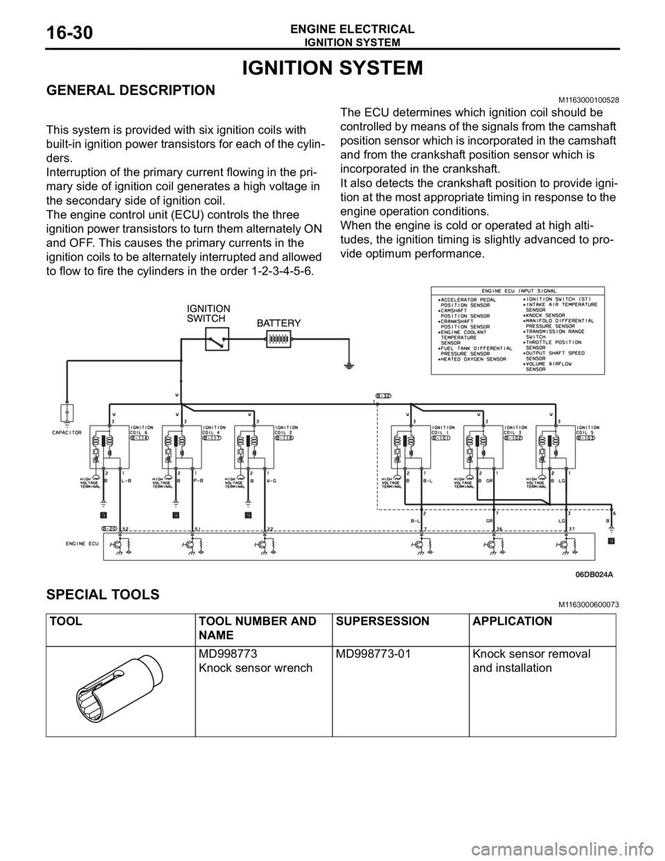
GENERAL DESCRIPTIONM1163000100528
This system is provided with six ignition coils with
built-in ignition power transistors for each of the cylin-
ders.
Interruption of the primary current flowing in the pri-
mary side of ignition coil generates a high voltage in
the secondary side of ignition coil.
The engine control unit (ECU) controls the three
ignition power transistors to turn them alternately ON
and OFF. This causes the primary currents in the
ignition coils to be alternately interrupted and allowed
to flow to fire the cylinders in the order 1-2-3-4-5-6.The ECU determines which ignition coil should be
controlled by means of the signals from the camshaft
position sensor which is incorporated in the camshaft
and from the crankshaft position sensor which is
incorporated in the crankshaft.
It also detects the crankshaft position to provide igni-
tion at the most appropriate timing in response to the
engine operation conditions.
When the engine is cold or operated at high alti-
tudes, the ignition timing is slightly advanced to pro-
vide optimum performance.
SPECIAL TOOLSM1163000600073
TOOL TOOL NUMBER AND
NAMESUPERSESSION APPLICATION
MD998773
Knock sensor wrenchMD998773-01 Knock sensor removal
and installation
Page 1038 of 1500
REAR BUMPER ASSEMBLY
EXTERIOR51-5
REAR BUMPER ASSEMBLY
REMOVAL AND INSTALLATIONM1511001900427
REMOVAL STEPS
REAR COMBINATION LIGHT
(REFER TO GROUP 54A, REAR
COMBINATION LIGHT P.54A-161).
REAR END TRIM REFER TO
GROUP 52A, TRIMS P.52A-11).
1. REAR SPLASH SHIELD2. TAPPING SCREW
3. REAR BUMPER ASSEMBLY
4. REAR BUMPER CENTER BRACKET
5. REAR BUMPER SIDE BRACKET
6. REAR BUMPER CORES, LH/RH
7. REAR BUMPER REINFORCEMENT REMOVAL STEPS (Continued)
Page 1044 of 1500
REAR SPOILER
EXTERIOR51-11
REAR SPOILER
REMOVAL AND INSTALLATIONM1511006100147
REMOVAL STEPS
TRUNK LID BUMPER (REFER TO
GROUP 42, TRUNK LID P.42-63).
1. REAR SPOILER ASSEMBLY2PACKING
3 HIGH-MOUNTED STOPLIGHT
(REFER TO GROUP 54A,
HIGH-MOUNTED STOPLIGHT
P.54A-166). REMOVAL STEPS (Continued)
Page 1056 of 1500
WINDSHIELD WIPER AND WASHER
EXTERIOR51-23
WINDSHIELD WASHER
REMOVAL AND INSTALLATIONM1511008200270
WINDSHIELD WASHER NOZZLE
REMOVAL STEPS
WINDSHIELD WASHER HOSE
CONNECTION
1. WINDSHIELD WASHER NOZZLE
WASHER HOSE REMOVAL STEPS
WINDSHIELD WASHER NOZZLE
CONNECTION
2. WINDSHIELD WASHER HOSEWASHER TANK REMOVAL STEPS
FRONT UNDER COVER RH (REFER
TO P.51-2).
FRONT SPLASH SHIELD RH
MOUNTING CLIPS (REFER TO
GROUP 42, FENDER P.42-10).
FRONT BUMPER (REFER TO
P.51-2).
HEAD LIGHT (REFER TO GROUP
54A, HEADLIGHT P.54A-153).
FRONT WASHER HOSE
CONNECTIONS
3. WASHER TANK ASSEMBLY
Page 1076 of 1500
Page 1077 of 1500
FENDER
BODY42-10
FENDER
REMOVAL AND INSTALLATIONM1421001900313
Pre-removal and Post-installation Operation
Front Bumper Assembly Removal and Installation (Refer
to GROUP 51, Front Bumper P.51-2).
Front Mud Guard Removal and Installation (Refer to
GROUP 51, Mud Guard P.51-12).
Headlight Removal and Installation (Refer to GROUP
54A, Headlight and Front Combination Light P.54A-153).
REMOVAL STEPS
1. SPLASH SHIELD MOUNTING CLIP
2. SPLASH SHIELD MOUNTING BOLT
3. SPLASH SHIELD
DOOR MIRROR COVER (REFER TO
GROUP 51, DOOR MIRROR
P.51-28).
FRONT DELTA GARNISH (REFER
TO GROUP 51, GARNISHES AND
MOLDING P.51-8).
4. FENDERREMOVAL STEPS (Continued)