2005 MITSUBISHI 380 light
[x] Cancel search: lightPage 1086 of 1500
WINDOW GLASS
BODY42-19
>>B<
windshield against the body, and place a mating mark on the
windshield and body.
The primer strengthens the adhesive, so be sure to
apply it evenly around the entire circumference. How-
ever, a too thick application will weaken the adhesive.
Do not touch the coated surface.
Do not apply the primer on the remaining adhesive
because of weakening the adhesive.
2. Soak a sponge in the primer, and apply evenly to the
windshield and the body in the specified places.
3. Allow the windshield to dry for at least three minutes after
applying primer.
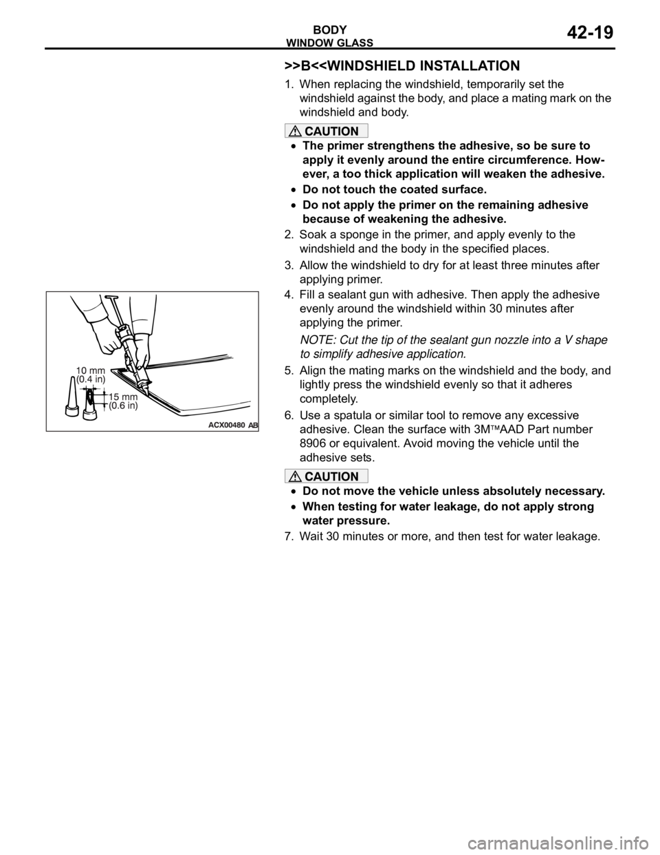
4. Fill a sealant gun with adhesive. Then apply the adhesive
evenly around the windshield within 30 minutes after
applying the primer.
NOTE: Cut the tip of the sealant gun nozzle into a V shape
to simplify adhesive application.
5. Align the mating marks on the windshield and the body, and
lightly press the windshield evenly so that it adheres
completely.
6. Use a spatula or similar tool to remove any excessive
adhesive. Clean the surface with 3M
AAD Part number
8906 or equivalent. Avoid moving the vehicle until the
adhesive sets.
Do not move the vehicle unless absolutely necessary.
When testing for water leakage, do not apply strong
water pressure.
7. Wait 30 minutes or more, and then test for water leakage.
Page 1129 of 1500
TRUNK LID
BODY42-62
TRUNK LID HEIGHT ADJUSTMENTM1421008300044
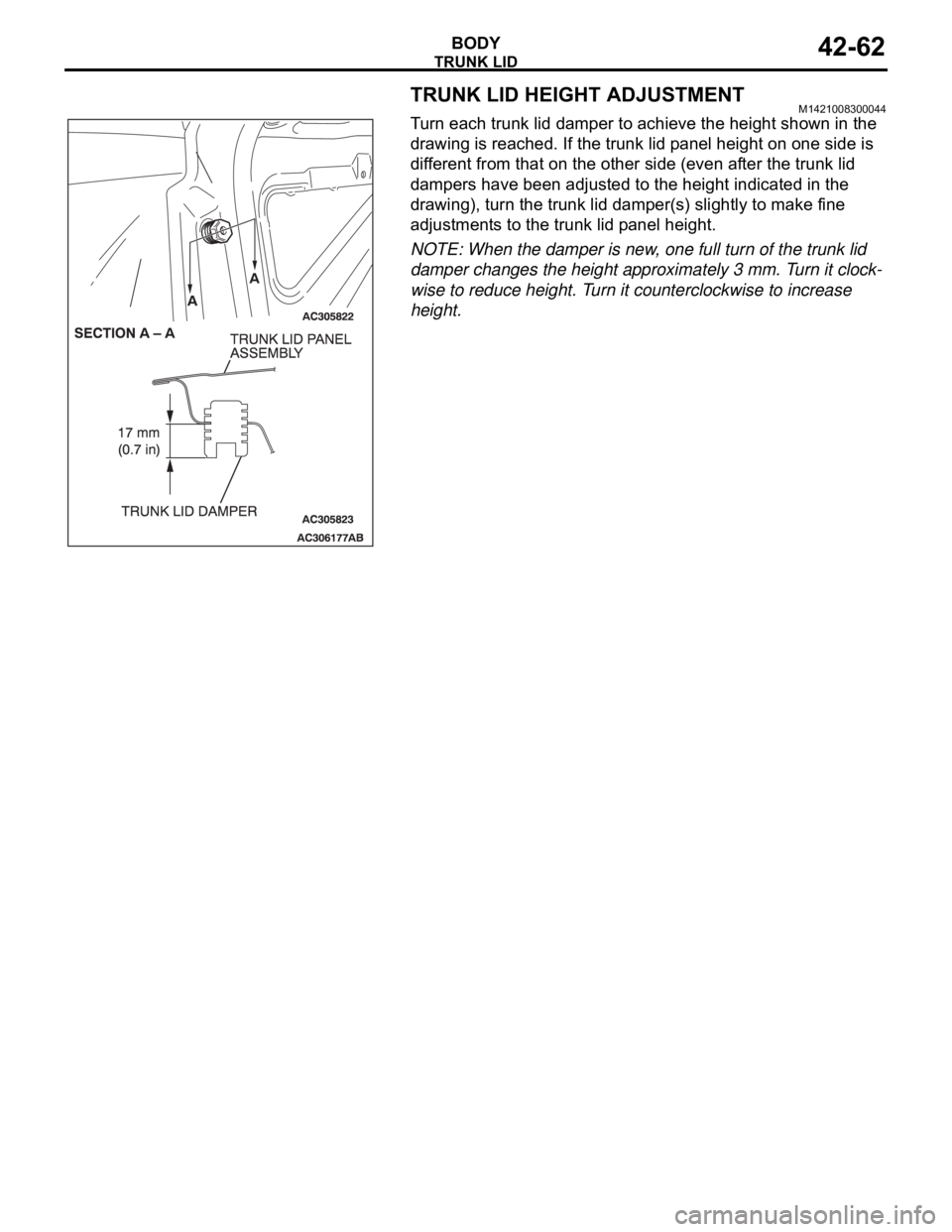
Turn each trunk lid damper to achieve the height shown in the
drawing is reached. If the trunk lid panel height on one side is
different from that on the other side (even after the trunk lid
dampers have been adjusted to the height indicated in the
drawing), turn the trunk lid damper(s) slightly to make fine
adjustments to the trunk lid panel height.
NOTE: When the damper is new, one full turn of the trunk lid
damper changes the height approximately 3 mm. Turn it clock-
wise to reduce height. Turn it counterclockwise to increase
height.
Page 1131 of 1500
TRUNK LID
BODY42-64
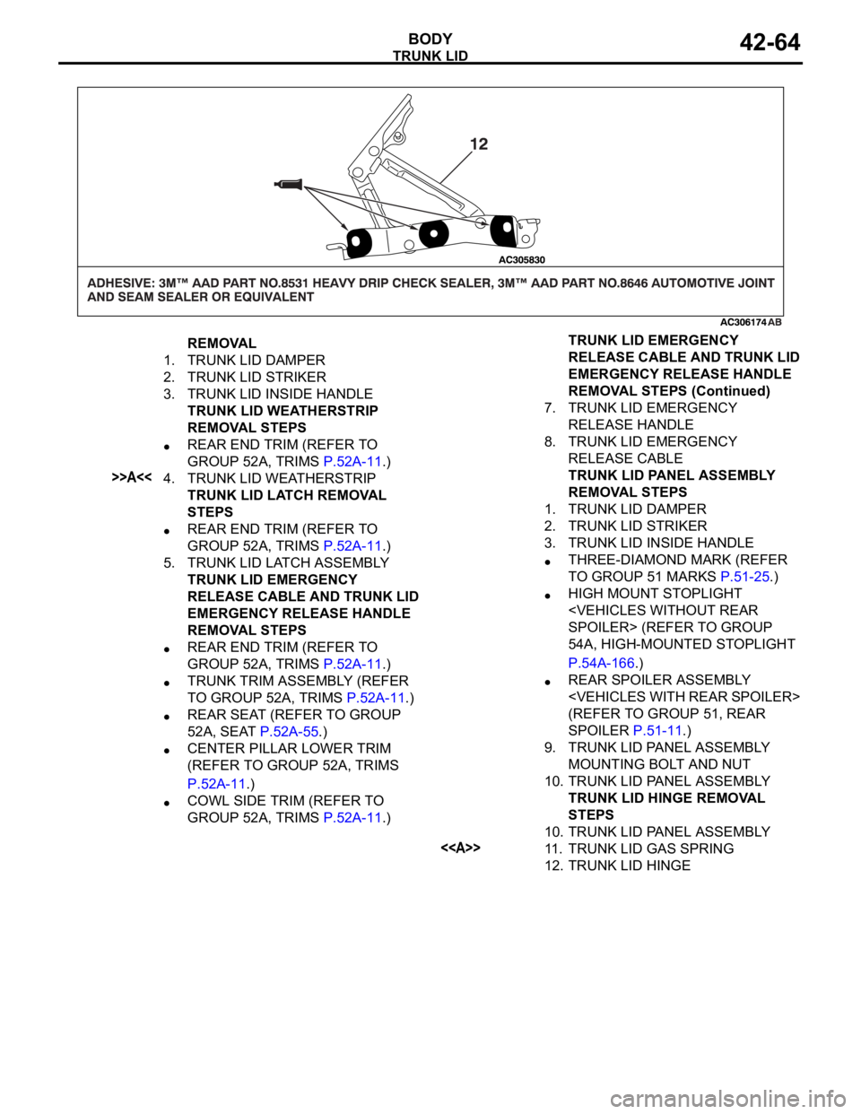
REMOVAL
1. TRUNK LID DAMPER
2. TRUNK LID STRIKER
3. TRUNK LID INSIDE HANDLE
TRUNK LID WEATHERSTRIP
REMOVAL STEPS
REAR END TRIM (REFER TO
GROUP 52A, TRIMS P.52A-11.)
>>A<<4. TRUNK LID WEATHERSTRIP
TRUNK LID LATCH REMOVAL
STEPS
REAR END TRIM (REFER TO
GROUP 52A, TRIMS P.52A-11.)
5. TRUNK LID LATCH ASSEMBLY
TRUNK LID EMERGENCY
RELEASE CABLE AND TRUNK LID
EMERGENCY RELEASE HANDLE
REMOVAL STEPS
REAR END TRIM (REFER TO
GROUP 52A, TRIMS P.52A-11.)
TRUNK TRIM ASSEMBLY (REFER
TO GROUP 52A, TRIMS P.52A-11.)
REAR SEAT (REFER TO GROUP
52A, SEAT P.52A-55.)
CENTER PILLAR LOWER TRIM
(REFER TO GROUP 52A, TRIMS
P.52A-11.)
COWL SIDE TRIM (REFER TO
GROUP 52A, TRIMS P.52A-11.)7. TRUNK LID EMERGENCY
RELEASE HANDLE
8. TRUNK LID EMERGENCY
RELEASE CABLE
TRUNK LID PANEL ASSEMBLY
REMOVAL STEPS
1. TRUNK LID DAMPER
2. TRUNK LID STRIKER
3. TRUNK LID INSIDE HANDLE
THREE-DIAMOND MARK (REFER
TO GROUP 51 MARKS P.51-25.)
HIGH MOUNT STOPLIGHT
54A, HIGH-MOUNTED STOPLIGHT
P.54A-166.)
REAR SPOILER ASSEMBLY
(REFER TO GROUP 51, REAR
SPOILER P.51-11.)
9. TRUNK LID PANEL ASSEMBLY
MOUNTING BOLT AND NUT
10. TRUNK LID PANEL ASSEMBLY
TRUNK LID HINGE REMOVAL
STEPS
10. TRUNK LID PANEL ASSEMBLY
<>11. TRUNK LID GAS SPRING
12. TRUNK LID HINGETRUNK LID EMERGENCY
RELEASE CABLE AND TRUNK LID
EMERGENCY RELEASE HANDLE
REMOVAL STEPS (Continued)
Page 1134 of 1500

KEYLESS ENTRY SYSTEM
BODY42-67
KEYLESS ENTRY SYSTEM
GENERAL DESCRIPTIONBGBJABIE
Antenna and receiver are incorporated in the
ETACS-ECU.
ID code can be registered by using Diagnostic
tool (MUT-III).
Transmitter is a key holder type, which incorpo-
rates lock button, unlock button, trunk button and
panic button
When the transmitter unlock button is pressed
once, the driver's door will be unlocked. If the but-
ton is pressed twice, all the doors will be
unlocked. The adjustment function also allows
you to open all the doors by pressing the unlock
button only once. For further details on using the
multi-center display to adjust the unlock opera-
tion, refer to GROUP 54B, On-vehicle Service
P.54B-486.
When the transmitter is operated, the answer-
back function will work as follows:
The answerback operation can be altered as fol-
lows:NOTE: Enabling/disabling the hazard warning
light flashing, the horn sounding in accordance
with the answerback function. For further details
on using the transmitter to adjust answerback,
P.42-72 see the section below. For further details
on using the multi-center display to adjust
answerback, refer to GROUP 54B, On-vehicle
Service P.54B-486. ITEM OPERATION
DOORS LOCKED DOORS UNLOCKED
Dome light Flashes once Illuminates for 15 seconds
Turn-signal lights (RH and LH) Flashes once Flashes twice
Horn Sounds once when the lock button
is pressed with all the doors locked-
ITEM ADJUSTMENT ITEM ADJUSTMENT DETAIL
Keyless entry system
confirmation by turn
signal lightsAdjustment of hazard answerback
when the transmitter is used to
lock doorsWhen adjusting hazard answerback after the
doors are locked with the transmitter, the
following flashing conditions can be selected.
a. Flash (default)
b. No flash
Adjustment of hazard answerback
when the transmitter is used to
unlock doorsWhen adjusting hazard answerback after the
doors are unlocked with the transmitter, the
following flashing conditions can be selected.
a. Flash (default)
b. No flash
Keyless entry system
confirmation by hornAdjustment of horn answerback
when the transmitter is used to
lock doorsWhen adjusting horn answerback after the
doors are locked with the transmitter, the
following horn conditions can be selected.
a. Horn sounds
b. Horn sounds if doors are already locked
(default)
c. Horn does not sound
Page 1138 of 1500

KEYLESS ENTRY SYSTEM
BODY42-71
KEYLESS ENTRY SYSTEM INSPECTIONBGBHCDAE
Check the following items. If defective, refer to GROUP 54B,
SWS Diagnosis P.54B-10).
1. Operate the transmitter to check that the doors can be
locked and unlocked.
NOTE: The adjustment function allows you to change the
unlock operation setting as follows. Prior to that check, con-
firm which setting is activated.
.
a. When the unlock button is pressed once, the driver's
door will be unlocked. Then when the button is pressed
once again, all the doors will be opened (initial setting).
b. When the unlock button is pressed only once, all the
doors will be opened.
2. Press the trunk lid button of transmitter twice (press once,
and then press again within 5 seconds) and confirm that the
trunk lid opens.
3. Operate the transmitter to check that the answerback
function works in response to doors locking/unlocking.
NOTE: The adjustment function allows you to change the
hazard answerback setting as follows. Prior to that check,
confirm which setting is activated.
.
a. Turn-signal lights: Flash once when doors are locked,
and twice when unlocked (initial setting)
b. Turn-signal lights: Flash once when doors are locked,
but does not flash when unlocked.
c. Turn-signal lights: Do not flash when doors are locked,
but flash twice when unlocked.
d. Turn-signal lights: Do not flash when doors are locked
and unlocked.
NOTE: The adjustment function allows you to change the
horn answerback setting as follows. Prior to that check, con-
firm which setting is activated.
.
a. Horn: Sounds once when the lock button is pressed.
b. Horn: Sounds once when the lock button is pressed (ini-
tial setting).
c. Horn: Does not sound.
KEYLESS ENTRY SYSTEM TIMER LOCK
FUNCTION INSPECTION
BGBEBDIA
If the doors are not locked within 30 seconds after the unlock
button is pressed, refer to GROUP 54B, SWS Diagnosis
P.54B-10.
NOTE: If either of the doors is opened or the key is inserted in
the ignition switch within that 30-second period, the timer lock
function will be cancelled.
Page 1139 of 1500

KEYLESS ENTRY SYSTEM
BODY42-72
NOTE: The adjustment function allows you to change the timer
lock period from 30 seconds (initial setting) to 60, 120 or 180
seconds. Prior to this inspection, confirm which setting is acti-
vated.
ENABLING/DISABLING THE ANSWERBACK
FUNCTION
BGBDGCGD
When the doors are locked or unlocked by using the transmit-
ter, the dome light will flash/illuminate, the turn-signal lights will
flash (hazard answerback), or the horn will sound (horn
answerback) to inform the driver.
The hazard answerback and horn answerback functions can be
enabled or disabled according to the following procedure:
ENABLING/DISABLING THE HAZARD
ANSWERBACK FUNCTION
.
How to adjust hazard answerback when the trans-
mitter is used to lock doors
1. Remove the ignition key.
2. Push the ”unlock” button and then push the ”lock“ button
within 4 seconds to 10 seconds.
3. Release the ”lock” button within 10 seconds after Step 2 and
then release the “unlock” button. The ETACS-ECU tone
alarm will sound, indicating that the hazard answerback
function can be enabled or disabled when the doors are
locked.
Enable the hazard answerback function when the
doors are locked: The ETACS-ECU tone alarm will
sound once.
Disable the hazard answerback function when the
doors are locked: The ETACS-ECU tone alarm will
sound twice.
.
How to adjust hazard answerback when the
transmitter is used to unlock doors
1. Remove the ignition key.
2. Push the ”unlock” button and then push the ”lock“ button
within 4 seconds to 10 seconds.
3. Release the ”lock” button within 10 seconds after Step 2 and
then release the “unlock” button. The ETACS-ECU tone
alarm will sound, indicating that the hazard answerback
function can be enabled or disabled when the door are
unlocked.
Enable the hazard answerback function when the
doors are unlocked: The ETACS-ECU tone alarm
will sound once.
Disable the hazard answerback function when the
doors are unlocked: The ETACS-ECU tone alarm
will sound twice.
Page 1141 of 1500
KEYLESS ENTRY SYSTEM
BODY42-74
To prevent damage to special tool MB991824 (V.C.I.),
always turn the ignition switch to “LOCK” (OFF) position
before connecting or disconnecting special tool MB991824
(V.C.I.).
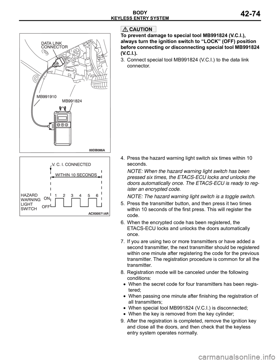
3. Connect special tool MB991824 (V.C.I.) to the data link
connector.
4. Press the hazard warning light switch six times within 10
seconds.
NOTE: When the hazard warning light switch has been
pressed six times, the ETACS-ECU locks and unlocks the
doors automatically once. The ETACS-ECU is ready to reg-
ister an encrypted code.
NOTE: The hazard warning light switch is a toggle switch.
5. Press the transmitter button, and then press it two times
within 10 seconds of the first press. This will register the
code.
6. When the encrypted code has been registered, the
ETACS-ECU locks and unlocks the doors automatically
once.
7. If you are using two or more transmitters or have added a
second transmitter, the next transmitter should be registered
within one minute after registering the code for the previous
transmitter. The registration procedure is common for all the
transmitter.
8. Registration mode will be canceled under the following
conditions:
When the secret code for four transmitters has been regis-
tered;
When passing one minute after finishing the registration of
all transmitters;
When special tool MB991824 (V.C.I.) is disconnected;
When the key is removed from the key cylinder;
9. After the registration is completed, remove the ignition key
and close all the doors, and then check that the keyless
entry system operates normally.
Page 1142 of 1500
SUNROOF ASSEMBLY
BODY42-75
SUNROOF ASSEMBLY
GENERAL DESCRIPTIONM1426000100234
A motor-driven inner slide-type glass sunroof with a
tilt-up mechanism is available in some models as a
standard or optional equipment. Even when the sun-
roof is fully closed, a sufficient amount of lighting and
a feeling of openness can still be obtained by open-
ing the sunroof sunshade.
SUNROOF DIAGNOSISM1426000700311
The sunroof system is controlled by the Simplified
Wiring System (SWS). Refer to GROUP 54B, SWS
Diagnosis P.54B-57.
SPECIAL TOOLM1426000600228
ON-VEHICLE SERVICE
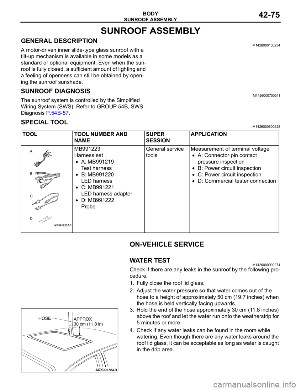
WAT E R T ES TM1426000900274
Check if there are any leaks in the sunroof by the following pro-
cedure.
1. Fully close the roof lid glass.
2. Adjust the water pressure so that water comes out of the
hose to a height of approximately 50 cm (19.7 inches) when
the hose is held vertically facing upwards.
3. Hold the end of the hose approximately 30 cm (11.8 inches)
above the roof and let the water run onto the weatherstrip for
5 minutes or more.
4. Check if any water leaks can be found in the room while
watering. Even though there are any water leaks around the
roof lid glass, it can be acceptable as long as water is caught
in the drip area. TOOL TOOL NUMBER AND
NAMESUPER
SESSIONAPPLICATION
MB991223
Harness set
A: MB991219
Test harness
B: MB991220
LED harness
C: MB991221
LED harness adapter
D: MB991222
ProbeGeneral service
toolsMeasurement of terminal voltage
A: Connector pin contact
pressure inspection
B: Power circuit inspection
C: Power circuit inspection
D: Commercial tester connection