Page 1393 of 1500
AUTO-CRUISE CONTROL
ENGINE AND EMISSION CONTROL17-62
INSPECTION PROCEDURE 7: When "CRUISE" (MAIN) Switch is Turned "ON", "CRUISE" Indicator
Light Inside Combination Meter does not Illuminate. (However, Auto-cruise Control System is
Normal).
.
Page 1396 of 1500

AUTO-CRUISE CONTROL
ENGINE AND EMISSION CONTROL17-65
DATA LIST REFERENCE TABLE - Auto Cruise ControlM1172002400471
When shifting the selector lever to "D" range, apply the brakes so that the vehicle does not move
forward.
Driving tests always need two persons: one driver and one observer.
NOTE: *:After the inspection is completed, disconnect the throttle position sensor connector, and then delete
the diagnostic trouble code using use of Diagnostic Tool MB991958. (Refer to P.17-11).
MUT-III
Diagnostic
To o l
DISPLAYITEM
NO.INSPECTION ITEM INSPECTION REQUIREMENT NORMAL
CONDITION
APS
SNS(MAIN)11 A c c e l e r a t o r p e d a l
position sensor (main)Ignition
switch:
"ON"Accelerator pedal: Released
435
1,035 mV
Accelerator pedal: Gradually
depressedIncreases in
response to the
pedal depression
stroke
Accelerator pedal: Fully
depressed4,000 mV or more
BRAKE SW 89 Stoplamp switch Brake pedal: Depressed ON
Brake pedal: Released OFF
CANCEL
CODE57 Cancel code Ignition switch: "ON" The cancel code,
which set when the
auto-cruise control
system was
cancelled at the
last time, is set
again.
CANCEL
SWITCH75 Auto-cruise
control
switchCANCEL "CANCEL" switch: ON ON
"CANCEL" switch: OFF OFF
CLUTCH SW 78 Transmission inhibitor
switchTransmission inhibitor switch: "P" or
"N"ON
Transmission inhibitor switch: Other
than aboveOFF
CRUISE 81 Auto-cruise control
system operationAuto-cruise control system: active ON
Auto-cruise control system: Inactive OFF
MAIN SW 86 Auto-cruise
control
switchCRUISE
(MAIN)"CRUISE" (MAIN) switch: "ON" ON
"CRUISE" (MAIN) switch: "OFF" OFF
RESUME
SWITCH91 Auto-cruise
control
switchACC/RES "ACC/RES" switch: ON ON
"ACC/RES" switch: OFF OFF
SET SWITCH 92 Auto-cruise
control
switchCOAST/S
ET"COAST/SET" switch: ON ON
"COAST/SET" switch: OFF OFF
STOPLIGHT
SW74 Stoplamp switch Brake pedal: Depressed ON
Brake pedal: Released OFF
Page 1399 of 1500
AUTO-CRUISE CONTROL
ENGINE AND EMISSION CONTROL17-68
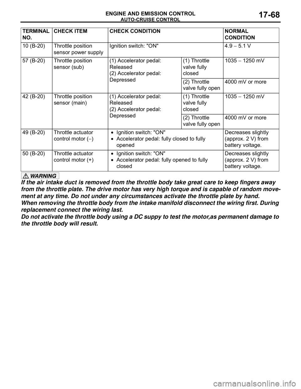
If the air intake duct is removed from the throttle body take great care to keep fingers away
from the throttle plate. The drive motor has very high torque and is capable of random move-
ment at any time. Do not under any circumstances activate the throttle plate by hand.
When removing the throttle body from the intake manifold disconnect the wiring first. During
replacement connect the wiring last.
Do not activate the throttle body using a DC suppy to test the motor,as permanent damage to
the throttle body will result.
10 (B-20) Throttle position
sensor power supplyIgnition switch: "ON" 4.9 5.1 V
57 (B-20) Throttle position
sensor (sub)(1) Accelerator pedal:
Released
(2) Accelerator pedal:
Depressed(1) Throttle
valve fully
closed1035
1250 mV
(2) Throttle
valve fully open4000 mV or more
42 (B-20) Throttle position
sensor (main)(1) Accelerator pedal:
Released
(2) Accelerator pedal:
Depressed(1) Throttle
valve fully
closed1035
1250 mV
(2) Throttle
valve fully open4000 mV or more
49 (B-20) Throttle actuator
control motor (
)
Ignition switch: "ON"
Accelerator pedal: fully closed to fully
openedDecreases slightly
(approx. 2 V) from
battery voltage.
50 (B-20) Throttle actuator
control motor (+)
Ignition switch: "ON"
Accelerator pedal: fully opened to fully
closedDecreases slightly
(approx. 2 V) from
battery voltage. TERMINAL
NO.CHECK ITEM CHECK CONDITION NORMAL
CONDITION
Page 1404 of 1500
AUTO-CRUISE CONTROL
ENGINE AND EMISSION CONTROL17-73
AUTO-CRUISE CONTROL SYSTEM COMPONENT
CHECK
M1172001700316
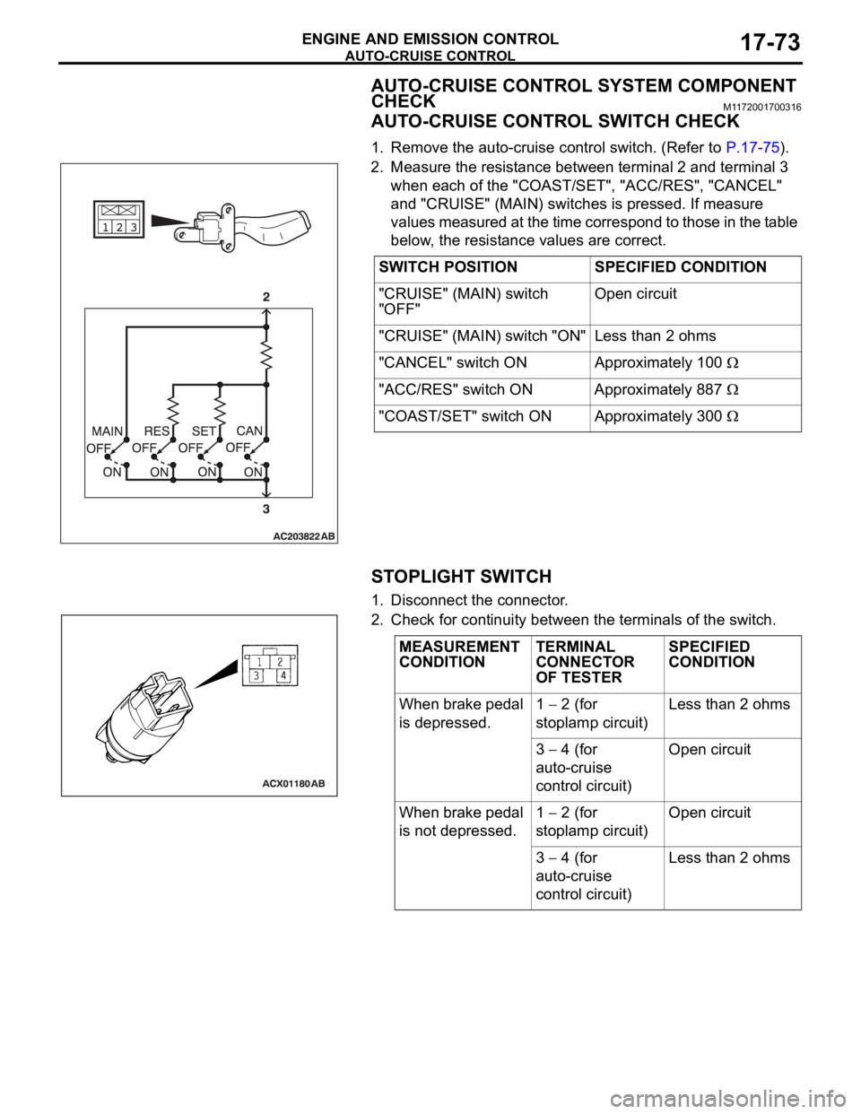
AUTO-CRUISE CONTROL SWITCH CHECK
1. Remove the auto-cruise control switch. (Refer to P.17-75).
2. Measure the resistance between terminal 2 and terminal 3
when each of the "COAST/SET", "ACC/RES", "CANCEL"
and "CRUISE" (MAIN) switches is pressed. If measure
values measured at the time correspond to those in the table
below, the resistance values are correct.
STOPLIGHT SWITCH
1. Disconnect the connector.
2. Check for continuity between the terminals of the switch.SWITCH POSITION SPECIFIED CONDITION
"CRUISE" (MAIN) switch
"OFF"Open circuit
"CRUISE" (MAIN) switch "ON" Less than 2 ohms
"CANCEL" switch ON Approximately 100
"ACC/RES" switch ON Approximately 887
"COAST/SET" switch ON Approximately 300
MEASUREMENT
CONDITIONTERMINAL
CONNECTOR
OF TESTERSPECIFIED
CONDITION
When brake pedal
is depressed.1
2 (for
stoplamp circuit)Less than 2 ohms
3
4 (for
auto-cruise
control circuit)Open circuit
When brake pedal
is not depressed.1
2 (for
stoplamp circuit)Open circuit
3
4 (for
auto-cruise
control circuit)Less than 2 ohms
Page 1406 of 1500
AUTO-CRUISE CONTROL
ENGINE AND EMISSION CONTROL17-75
AUTO-CRUISE CONTROL
REMOVAL AND INSTALLATIONM1172001400467
Before removal of the air bag module, refer to GROUP 52B, SRS Service Precautions
P.52B-16 and GROUP 52B, Air Bag Module and Clock Spring P.52B-237.
CONTROL SWITCH REMOVAL
STEPS
1. AIR BAG MODULE
SIDE> (REFER TO GROUP 52B, AIR
BAG MODULES AND CLOCK
SPRING P.52B-237)
2. STEERING WHEEL ASSEMBLY
(REFER TO GROUP 37, STEERING
WHEEL P.37-23)
3. LOWER COVER CAP
4. AUTO-CRUISE CONTROL SWITCH
CONTROL UNIT REMOVAL
5. Engine ECU [REFER TO GROUP
13A, Engine ECU 13A-675] SENSOR REMOVAL STEPS
6. TRANSMISSION INHIBITOR
SWITCH (REFER TO GROUP 23B,
AUTOMATIC TRANSMISSION)
7. THROTTLE BODY (BUILT-IN
THROTTLE POSITION SENSOR
AND THROTTLE ACTUATOR
CONTROL MOTOR) (REFER TO
GROUP 13A, THROTTLE BODY
13A-660)
8. ACCELERATOR PEDAL (BUILT-IN
ACCELERATOR PEDAL POSITION
SENSOR) (REFER TO GROUP 17,
ACCELERATOR PEDAL P.17-9)
9. STOPLIGHT SWITCH (REFER TO
GROUP 35A, BRAKE PEDAL
P.35A-24)
Page 1414 of 1500
EMISSION CONTROL
ENGINE AND EMISSION CONTROL17-83
Required Special Tool:
MB995061: Purge Flow Indicator
1. Disconnect the purge hose from the evaporative emission
(EVAP) purge solenoid, and connect special tool MB995061
between the EVAP purge solenoid and the purge hose.
2. Before inspection, set the vehicle in the following conditions:
Engine coolant temperature: 80 95C (176 203F)
Lights, electric cooling fan and accessories: OFF
Transaxle: P range
3. Run the engine at idle for more than four minutes.
4. Check the purge flow volume when engine is revved
suddenly several times.
Standard value: Momentarily 20 cm
3/s (2.5 SCFH) or
more.
5. If the purge flow volume is less than the standard value,
check it again with the vacuum hose disconnected from the
EVAP canister. If the purge flow volume is less than the
standard value, check the vacuum port and the vacuum
hose for clogging. Also check the EVAP purge solenoid. If
the purge flow volume is at the standard value, replace the
EVAP canister.
EVAPORATIVE EMISSION PURGE SOLENOID
CHECK
M1173001700289
1. Disconnect the vacuum hose (black, black with red paint
mark) from the evaporative emission (EVAP) purge
solenoid.
NOTE: When disconnecting the vacuum hose, always place
an identification mark so that it can be reconnected at its
original position.
2. Disconnect the harness connector.
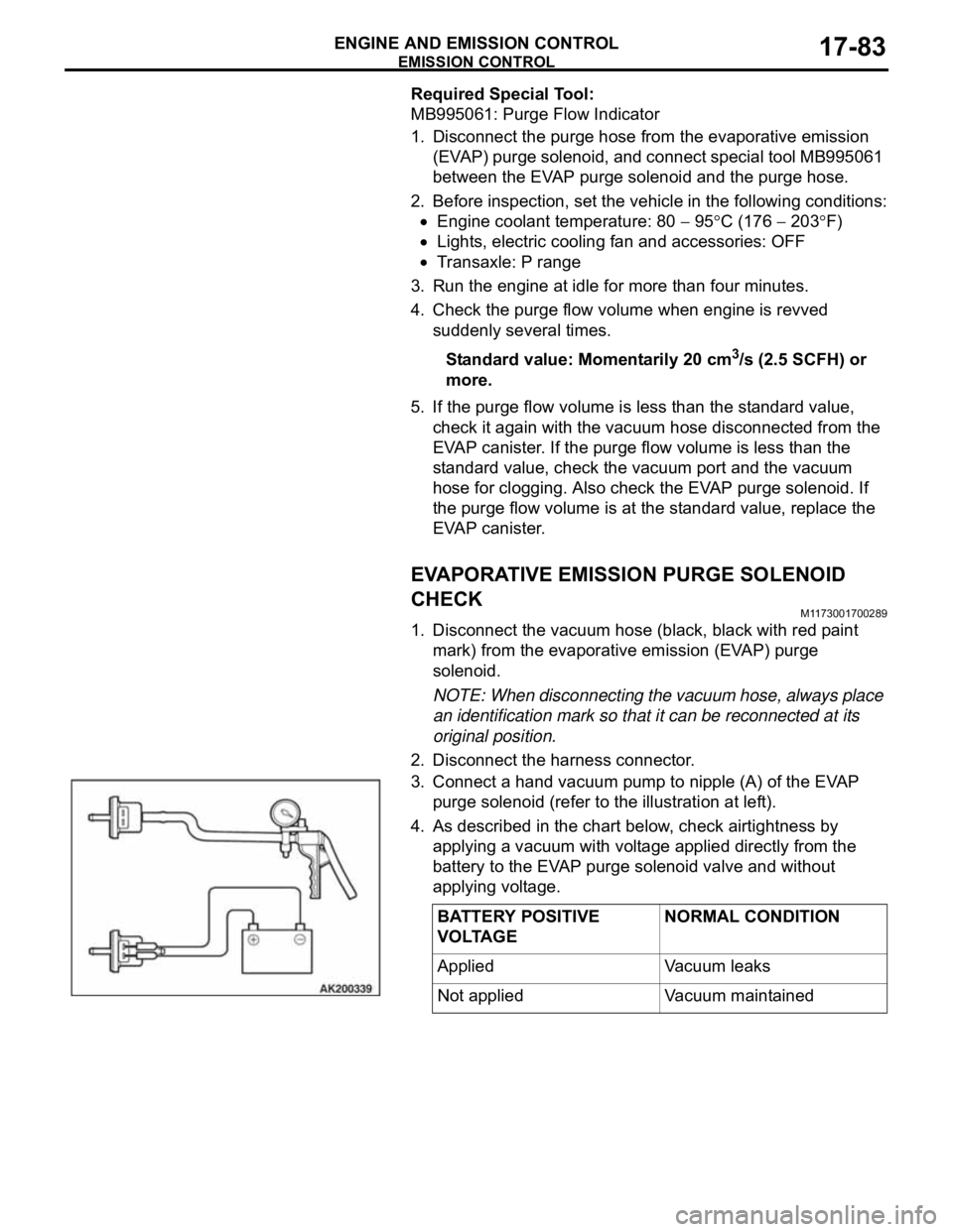
3. Connect a hand vacuum pump to nipple (A) of the EVAP
purge solenoid (refer to the illustration at left).
4. As described in the chart below, check airtightness by
applying a vacuum with voltage applied directly from the
battery to the EVAP purge solenoid valve and without
applying voltage.
BATTERY POSITIVE
VOLTAGENORMAL CONDITION
Applied Vacuum leaks
Not applied Vacuum maintained
Page 1434 of 1500
DRIVE SHAFT ASSEMBLY
FRONT AXLE26-17
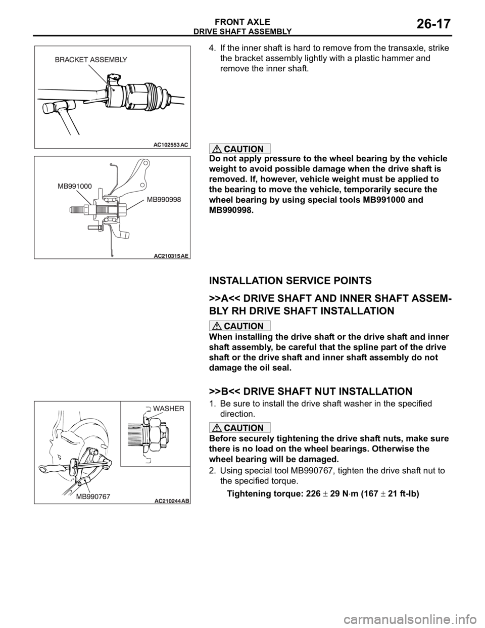
4. If the inner shaft is hard to remove from the transaxle, strike
the bracket assembly lightly with a plastic hammer and
remove the inner shaft.
Do not apply pressure to the wheel bearing by the vehicle
weight to avoid possible damage when the drive shaft is
removed. If, however, vehicle weight must be applied to
the bearing to move the vehicle, temporarily secure the
wheel bearing by using special tools MB991000 and
MB990998.
INSTALLATION SERVICE POINTS
.
>>A<< DRIVE SHAFT AND INNER SHAFT ASSEM-
BLY RH DRIVE SHAFT INSTALLATION
When installing the drive shaft or the drive shaft and inner
shaft assembly, be careful that the spline part of the drive
shaft or the drive shaft and inner shaft assembly do not
damage the oil seal.
.
>>B<< DRIVE SHAFT NUT INSTALLATION
1. Be sure to install the drive shaft washer in the specified
direction.
Before securely tightening the drive shaft nuts, make sure
there is no load on the wheel bearings. Otherwise the
wheel bearing will be damaged.
2. Using special tool MB990767, tighten the drive shaft nut to
the specified torque.
Tightening torque: 226
29 Nm (167 21 ft-lb)
Page 1461 of 1500
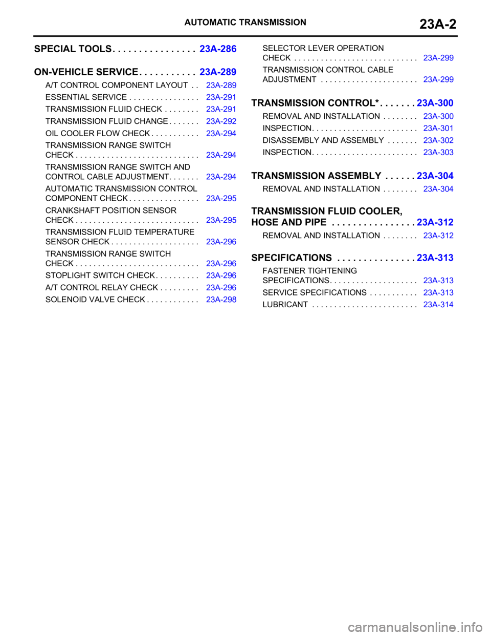
AUTOMATIC TRANSMISSION23A-2
SPECIAL TOOLS . . . . . . . . . . . . . . . .23A-286
ON-VEHICLE SERVICE. . . . . . . . . . .23A-289
A/T CONTROL COMPONENT LAYOUT . . 23A-289
ESSENTIAL SERVICE . . . . . . . . . . . . . . . . 23A-291
TRANSMISSION FLUID CHECK . . . . . . . . 23A-291
TRANSMISSION FLUID CHANGE . . . . . . . 23A-292
OIL COOLER FLOW CHECK . . . . . . . . . . . 23A-294
TRANSMISSION RANGE SWITCH
CHECK . . . . . . . . . . . . . . . . . . . . . . . . . . . . 23A-294
TRANSMISSION RANGE SWITCH AND
CONTROL CABLE ADJUSTMENT. . . . . . . 23A-294
AUTOMATIC TRANSMISSION CONTROL
COMPONENT CHECK . . . . . . . . . . . . . . . . 23A-295
CRANKSHAFT POSITION SENSOR
CHECK . . . . . . . . . . . . . . . . . . . . . . . . . . . . 23A-295
TRANSMISSION FLUID TEMPERATURE
SENSOR CHECK . . . . . . . . . . . . . . . . . . . . 23A-296
TRANSMISSION RANGE SWITCH
CHECK . . . . . . . . . . . . . . . . . . . . . . . . . . . . 23A-296
STOPLIGHT SWITCH CHECK . . . . . . . . . . 23A-296
A/T CONTROL RELAY CHECK . . . . . . . . . 23A-296
SOLENOID VALVE CHECK . . . . . . . . . . . . 23A-298SELECTOR LEVER OPERATION
CHECK . . . . . . . . . . . . . . . . . . . . . . . . . . . . 23A-299
TRANSMISSION CONTROL CABLE
ADJUSTMENT . . . . . . . . . . . . . . . . . . . . . . 23A-299
TRANSMISSION CONTROL* . . . . . . .23A-300
REMOVAL AND INSTALLATION . . . . . . . . 23A-300
INSPECTION. . . . . . . . . . . . . . . . . . . . . . . . 23A-301
DISASSEMBLY AND ASSEMBLY . . . . . . . 23A-302
INSPECTION. . . . . . . . . . . . . . . . . . . . . . . . 23A-303
TRANSMISSION ASSEMBLY . . . . . .23A-304
REMOVAL AND INSTALLATION . . . . . . . . 23A-304
TRANSMISSION FLUID COOLER,
HOSE AND PIPE . . . . . . . . . . . . . . . .23A-312
REMOVAL AND INSTALLATION . . . . . . . . 23A-312
SPECIFICATIONS . . . . . . . . . . . . . . .23A-313
FASTENER TIGHTENING
SPECIFICATIONS. . . . . . . . . . . . . . . . . . . . 23A-313
SERVICE SPECIFICATIONS . . . . . . . . . . . 23A-313
LUBRICANT . . . . . . . . . . . . . . . . . . . . . . . . 23A-314