2005 MITSUBISHI 380 ABS
[x] Cancel search: ABSPage 1216 of 1500
PARKING BRAKE LINING AND DRUM
PARKING BRAKES36-9
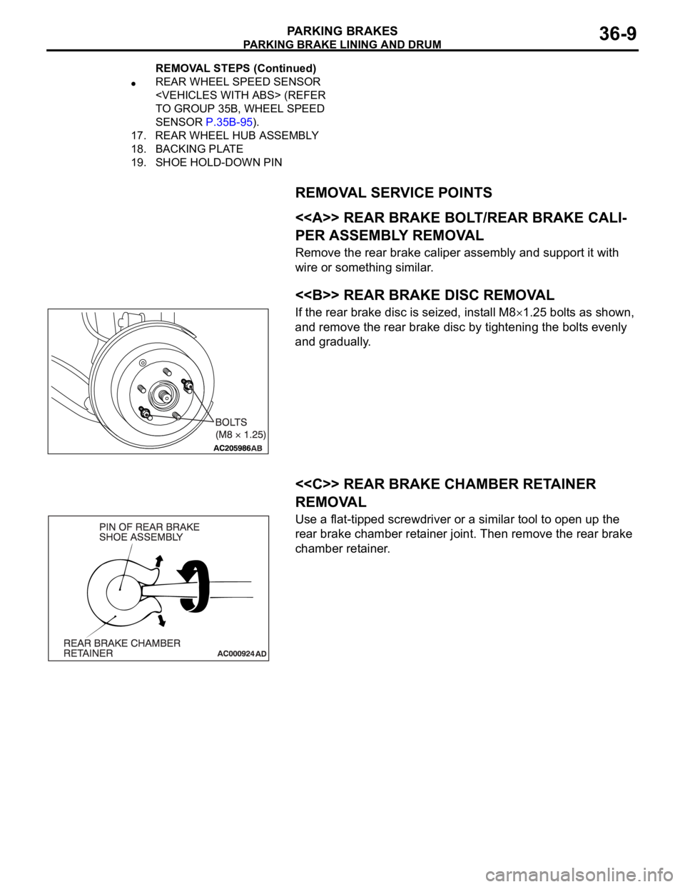
REMOVAL SERVICE POINTS
.
<> REAR BRAKE BOLT/REAR BRAKE CALI-
PER ASSEMBLY REMOVAL
Remove the rear brake caliper assembly and support it with
wire or something similar.
.
<> REAR BRAKE DISC REMOVAL
If the rear brake disc is seized, install M81.25 bolts as shown,
and remove the rear brake disc by tightening the bolts evenly
and gradually.
.
<
REMOVAL
Use a flat-tipped screwdriver or a similar tool to open up the
rear brake chamber retainer joint. Then remove the rear brake
chamber retainer.
REAR WHEEL SPEED SENSOR
TO GROUP 35B, WHEEL SPEED
SENSOR P.35B-95).
17. REAR WHEEL HUB ASSEMBLY
18. BACKING PLATE
19. SHOE HOLD-DOWN PIN
REMOVAL STEPS (Continued)
Page 1224 of 1500

HOW TO USE THIS MANUAL
GENERAL00-3
HOW TO USE THIS MANUALM1001000100897
MAINTENANCE, REPAIR AND
SERVICING EXPLANATIONS
This manual provides explanations, etc. concerning
procedures for the inspection, maintenance, repair
and servicing of the subject model. Unless otherwise
specified, each service procedure covers all models.
Procedures covering specific models are identified
by the model codes, or similar designation (engine
type, transaxle type, etc). A description of these des-
ignations is covered in this manual under "VEHICLE
IDENTIFICATION."
.
ON-VEHICLE SERVICE
The "ON-VEHICLE SERVICE" section has proce-
dures for performing inspections and adjustments of
particularly important components. These proce-
dures are done with regard to maintenance and ser-
vicing, but other inspections (looseness, play,
cracking, damage, etc.) must also be performed.
.
SERVICE PROCEDURES
The service steps are arranged in numerical order.
Attention to be paid in performing vehicle service are
described in detail in SERVICE POINTS.
DEFINITION OF TERMS
.
STANDARD VALUE
Indicates the value used as the standard for judging
whether or not a part or adjustment is correct.
.
LIMIT
Shows the maximum or minimum value for judging
whether or not a part or adjustment is acceptable.
.
REFERENCE VALUE
Indicates the adjustment value prior to starting the
work (presented in order to facilitate assembly and
adjustment procedures, and so they can be com-
pleted in a shorter time).
.
DANGER, WARNING, AND CAUTION
DANGER, WARNING, and CAUTION call special
attention to a necessary action or to an action that
must be avoided. The differences among DANGER,
WARNING, and CAUTION are as follows:
If a DANGER is not followed, the result is severe
bodily harm or even death.
If a WARNING is not followed, the result could be
bodily injury.
If a CAUTION is not followed, the result could be
damage to the vehicle, vehicle components or
service equipment.
TIGHTENING TORQUE INDICATION
The tightening torque indicates a median and its tol-
erance by a unit of N
m (in-lb.) or Nm (ft.-lb.). For
fasteners with no assigned torque value, refer to
P.00-32.
SPECIAL TOOL NOTE
Only MMC special tool part numbers are called out in
the repair sections of this manual. Please refer to the
special tool cross-reference chart located at the
beginning of each group, for the special tool number
that is available in your market.
ABBREVIATIONS
The following abbreviations are used in this manual
for classification of model types:
A/T:Automatic transaxle, or models equipped with
automatic transaxle.
MPI: Multipoint fuel injection, or engines equipped
with multiport fuel injection.
A/C: Air conditioning.
3.8L engine: 3.8 litre <6G75> engine, or a model
equipped with such an engine.
ABS: Anti-lock Braking System
TCL: Traction Control System
ECU: Electronic Control Unit
V.C.I.: Vehicle Communication Interface
SWS: Simplified Wiring System
CAN: Controller Area Network
M/T: Manual Transmission
SRS: Supplemental Restraint System
Page 1280 of 1500
13C-1
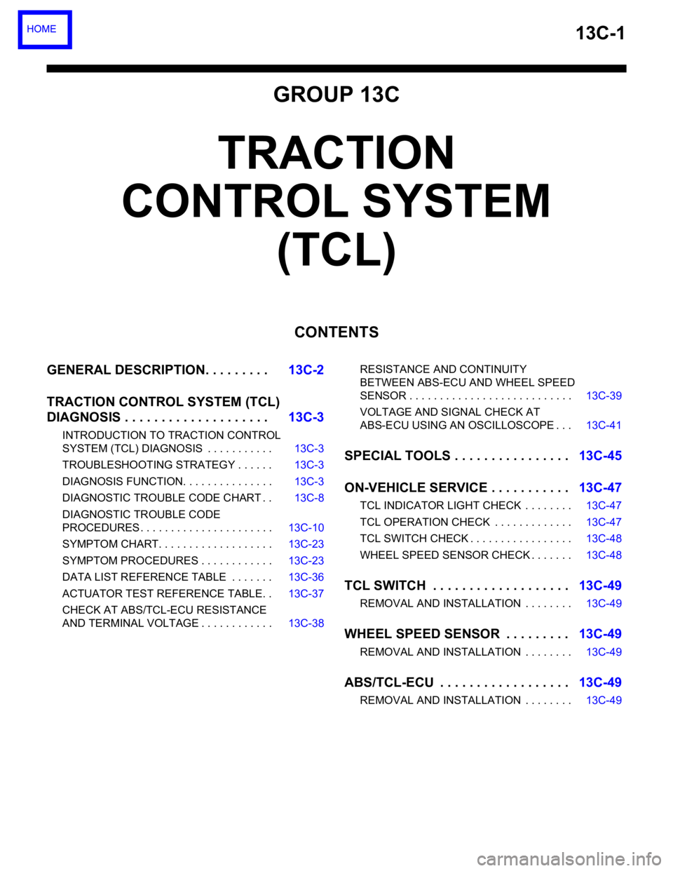
GROUP 13C
TRACTION
CONTROL SYSTEM
(TCL)
CONTENTS
GENERAL DESCRIPTION. . . . . . . . .13C-2
TRACTION CONTROL SYSTEM (TCL)
DIAGNOSIS . . . . . . . . . . . . . . . . . . . .13C-3
INTRODUCTION TO TRACTION CONTROL
SYSTEM (TCL) DIAGNOSIS . . . . . . . . . . . 13C-3
TROUBLESHOOTING STRATEGY . . . . . . 13C-3
DIAGNOSIS FUNCTION. . . . . . . . . . . . . . . 13C-3
DIAGNOSTIC TROUBLE CODE CHART . . 13C-8
DIAGNOSTIC TROUBLE CODE
PROCEDURES . . . . . . . . . . . . . . . . . . . . . . 13C-10
SYMPTOM CHART. . . . . . . . . . . . . . . . . . . 13C-23
SYMPTOM PROCEDURES . . . . . . . . . . . . 13C-23
DATA LIST REFERENCE TABLE . . . . . . . 13C-36
ACTUATOR TEST REFERENCE TABLE. . 13C-37
CHECK AT ABS/TCL-ECU RESISTANCE
AND TERMINAL VOLTAGE . . . . . . . . . . . . 13C-38RESISTANCE AND CONTINUITY
BETWEEN ABS-ECU AND WHEEL SPEED
SENSOR . . . . . . . . . . . . . . . . . . . . . . . . . . . 13C-39
VOLTAGE AND SIGNAL CHECK AT
ABS-ECU USING AN OSCILLOSCOPE . . . 13C-41
SPECIAL TOOLS . . . . . . . . . . . . . . . .13C-45
ON-VEHICLE SERVICE . . . . . . . . . . .13C-47
TCL INDICATOR LIGHT CHECK . . . . . . . . 13C-47
TCL OPERATION CHECK . . . . . . . . . . . . . 13C-47
TCL SWITCH CHECK . . . . . . . . . . . . . . . . . 13C-48
WHEEL SPEED SENSOR CHECK . . . . . . . 13C-48
TCL SWITCH . . . . . . . . . . . . . . . . . . .13C-49
REMOVAL AND INSTALLATION . . . . . . . . 13C-49
WHEEL SPEED SENSOR . . . . . . . . .13C-49
REMOVAL AND INSTALLATION . . . . . . . . 13C-49
ABS/TCL-ECU . . . . . . . . . . . . . . . . . .13C-49
REMOVAL AND INSTALLATION . . . . . . . . 13C-49
Page 1282 of 1500
TRACTION CONTROL SYSTEM (TCL) DIAGNOSIS
TRACTION CONTROL SYSTEM (TCL)13C-3
TRACTION CONTROL SYSTEM (TCL) DIAGNOSIS
INTRODUCTION TO TRACTION CONTROL SYSTEM (TCL) DIAGNOSISM1136004600026
TCL Diagnostic Trouble Code Detection
Conditions
TCL diagnostic trouble codes (TCL DTCs) are set
under different conditions, depending on the mal-
function detected. Most TCL DTCs will only be set
during vehicle operation. Some TCL DTCs will also
be set during the TCL self-check immediately after
the engine is started. When you check if an TCL DTC will be displayed again after the DTC has been
erased, you should recreate the TCL DTC set condi-
tions. Depending on the detection timing and set
conditions for the specific TCL DTC, you must either
drive the vehicle or turn the engine off and restart it.
To set the proper conditions for that DTC again, refer
to "TCL DTC SET CONDITIONS" for each TCL DTC
that you are trying to reset.
TROUBLESHOOTING STRATEGYM1136003100062
Use these steps to plan your diagnostic strategy. If
you follow them carefully, you will check most of the
possible causes of a TCL problem.
1. Gather information from the customer.
2. Verify that the condition described by the
customer exists.
3. Check the vehicle for any TCL DTC. (Refer to
P.13C-3, Diagnosis Function
How to Read and
Erase Diagnostic Trouble Codes).
4. If you can verify the condition but no TCL DTCs
are set, and the malfunction may be intermittent.
(Refer to GROUP 00, How to Use
Troubleshooting/Inspection Service Points
How
to Cope with Intermittent Malfunctions P.00-14).
5. If you can verify the condition but there is no TCL
DTCs, or the system cannot communicate with
diagnostic tool MB991958 (MUT-III sub
assembly), and find the fault. (Refer to P.13C-23,
Symptom Chart).6. If there is a TCL DTC, record the number of the
code, then erase the code from vehicle memory
using the diagnostic tool MB991958 (MUT-III sub
assembly). (Refer to P.13C-3, Diagnosis Function
How to Read and Erase Diagnostic Trouble
Codes).
7. Re-create the TCL DTC set conditions to see if
the same TCL DTC will set again. (Refer to
P.13C-3, Diagnosis Function
How to Read and
Erase Diagnostic Trouble Codes).
If the same TCL DTC sets again, perform the
diagnostic procedures for the set code. (Refer to
P.13C-8, Diagnostic Trouble Code Chart).
NOTE: If the ABS-8 ECU or the active wheel
speed sensor are disconnected, or if the wir-
ing is an open/ short circuit, the ABS 8 ECU
will shut off power supply to the respective
wheel speed sensor. All other wheel speed
sensors will operate normally. To restore the
power supply, the ignition switch must be
turned to the "OFF" position then to the "ON"
position again.
DIAGNOSIS FUNCTIONM1136003200025
HOW TO CONNECT THE DIAGNOSTIC TOOL
(MUT-III)
Required Special Tools:
MB991958: Diagnostic Tool (MUT-III Sub Assembly)
MB991824: Vehicle Communication Interface (V.C.I.)
MB991827: MUT-III USB Cable
MB991910: MUT-III Main Harness A
Page 1287 of 1500
TRACTION CONTROL SYSTEM (TCL) DIAGNOSIS
TRACTION CONTROL SYSTEM (TCL)13C-8
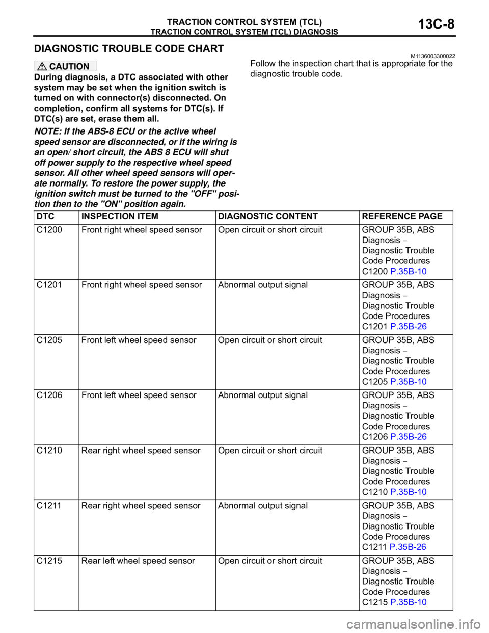
DIAGNOSTIC TROUBLE CODE CHARTM1136003300022
During diagnosis, a DTC associated with other
system may be set when the ignition switch is
turned on with connector(s) disconnected. On
completion, confirm all systems for DTC(s). If
DTC(s) are set, erase them all.
NOTE: If the ABS-8 ECU or the active wheel
speed sensor are disconnected, or if the wiring is
an open/ short circuit, the ABS 8 ECU will shut
off power supply to the respective wheel speed
sensor. All other wheel speed sensors will oper-
ate normally. To restore the power supply, the
ignition switch must be turned to the "OFF" posi-
tion then to the "ON" position again.Follow the inspection chart that is appropriate for the
diagnostic trouble code.
DTC INSPECTION ITEM DIAGNOSTIC CONTENT REFERENCE PAGE
C1200 Front right wheel speed sensor Open circuit or short circuit GROUP 35B, ABS
Diagnosis
Diagnostic Trouble
Code Procedures
C1200 P.35B-10
C1201 Front right wheel speed sensor Abnormal output signal GROUP 35B, ABS
Diagnosis
Diagnostic Trouble
Code Procedures
C1201 P.35B-26
C1205 Front left wheel speed sensor Open circuit or short circuitGROUP 35B, ABS
Diagnosis
Diagnostic Trouble
Code Procedures
C1205 P.35B-10
C1206 Front left wheel speed sensor Abnormal output signal GROUP 35B, ABS
Diagnosis
Diagnostic Trouble
Code Procedures
C1206 P.35B-26
C1210 Rear right wheel speed sensor Open circuit or short circuitGROUP 35B, ABS
Diagnosis
Diagnostic Trouble
Code Procedures
C1210 P.35B-10
C1211 Rear right wheel speed sensor Abnormal output signal GROUP 35B, ABS
Diagnosis
Diagnostic Trouble
Code Procedures
C1211 P.35B-26
C1215 Rear left wheel speed sensor Open circuit or short circuit GROUP 35B, ABS
Diagnosis
Diagnostic Trouble
Code Procedures
C1215 P.35B-10
Page 1288 of 1500
TRACTION CONTROL SYSTEM (TCL) DIAGNOSIS
TRACTION CONTROL SYSTEM (TCL)13C-9
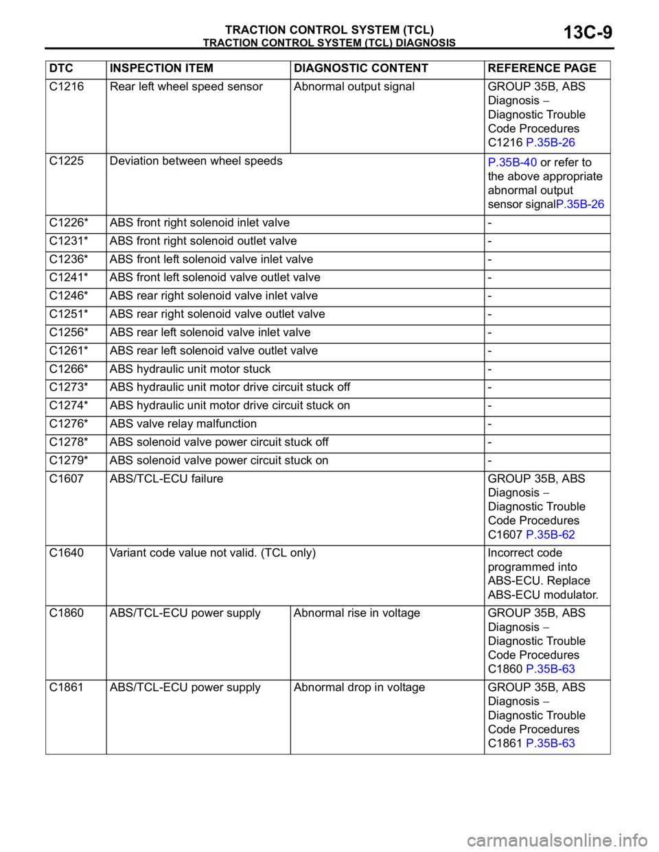
C1216 Rear left wheel speed sensor Abnormal output signal GROUP 35B, ABS
Diagnosis
Diagnostic Trouble
Code Procedures
C1216 P.35B-26
C1225 Deviation between wheel speeds
P.35B-40 or refer to
the above appropriate
abnormal output
sensor signalP.35B-26
C1226* ABS front right solenoid inlet valve -
C1231* ABS front right solenoid outlet valve -
C1236* ABS front left solenoid valve inlet valve -
C1241* ABS front left solenoid valve outlet valve -
C1246* ABS rear right solenoid valve inlet valve -
C1251* ABS rear right solenoid valve outlet valve -
C1256* ABS rear left solenoid valve inlet valve -
C1261* ABS rear left solenoid valve outlet valve -
C1266* ABS hydraulic unit motor stuck -
C1273* ABS hydraulic unit motor drive circuit stuck off -
C1274* ABS hydraulic unit motor drive circuit stuck on -
C1276* ABS valve relay malfunction -
C1278* ABS solenoid valve power circuit stuck off -
C1279* ABS solenoid valve power circuit stuck on -
C1607 ABS/TCL-ECU failure GROUP 35B, ABS
Diagnosis
Diagnostic Trouble
Code Procedures
C1607 P.35B-62
C1640 Variant code value not valid. (TCL only) Incorrect code
programmed into
ABS-ECU. Replace
ABS-ECU modulator.
C1860 ABS/TCL-ECU power supply Abnormal rise in voltage GROUP 35B, ABS
Diagnosis
Diagnostic Trouble
Code Procedures
C1860 P.35B-63
C1861 ABS/TCL-ECU power supply Abnormal drop in voltage GROUP 35B, ABS
Diagnosis
Diagnostic Trouble
Code Procedures
C1861 P.35B-63 DTC INSPECTION ITEM DIAGNOSTIC CONTENT REFERENCE PAGE
Page 1289 of 1500
TRACTION CONTROL SYSTEM (TCL) DIAGNOSIS
TRACTION CONTROL SYSTEM (TCL)13C-10
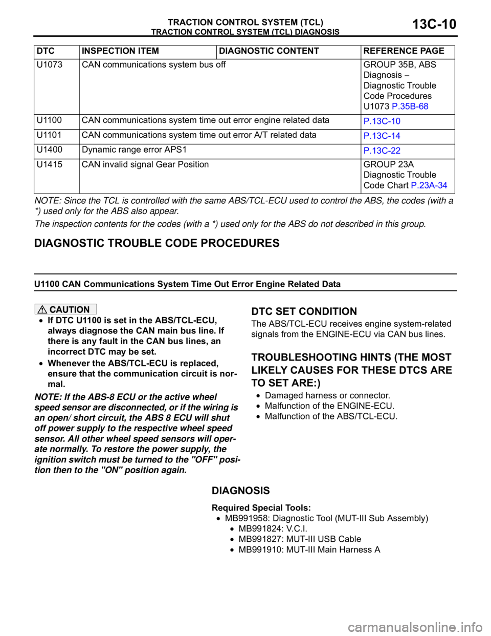
NOTE: Since the TCL is controlled with the same ABS/TCL-ECU used to control the ABS, the codes (with a
*) used only for the ABS also appear.
The inspection contents for the codes (with a *) used only for the ABS do not described in this group.
DIAGNOSTIC TROUBLE CODE PROCEDURES
U1100 CAN Communications System Time Out Error Engine Related Data
If DTC U1100 is set in the ABS/TCL-ECU,
always diagnose the CAN main bus line. If
there is any fault in the CAN bus lines, an
incorrect DTC may be set.
Whenever the ABS/TCL-ECU is replaced,
ensure that the communication circuit is nor-
mal.
NOTE: If the ABS-8 ECU or the active wheel
speed sensor are disconnected, or if the wiring is
an open/ short circuit, the ABS 8 ECU will shut
off power supply to the respective wheel speed
sensor. All other wheel speed sensors will oper-
ate normally. To restore the power supply, the
ignition switch must be turned to the "OFF" posi-
tion then to the "ON" position again.
.
DTC SET CONDITION
The ABS/TCL-ECU receives engine system-related
signals from the ENGINE-ECU via CAN bus lines.
.
TROUBLESHOOTING HINTS (THE MOST
LIKELY CAUSES FOR THESE DTCS ARE
TO SET ARE:)
Damaged harness or connector.
Malfunction of the ENGINE-ECU.
Malfunction of the ABS/TCL-ECU.
DIAGNOSIS
Required Special Tools:
MB991958: Diagnostic Tool (MUT-III Sub Assembly)
MB991824: V.C.I.
MB991827: MUT-III USB Cable
MB991910: MUT-III Main Harness A U1073 CAN communications system bus off GROUP 35B, ABS
Diagnosis
Diagnostic Trouble
Code Procedures
U1073 P.35B-68
U1100 CAN communications system time out error engine related data
P.13C-10
U1101 CAN communications system time out error A/T related data
P.13C-14
U1400 Dynamic range error APS1
P.13C-22
U1415 CAN invalid signal Gear Position GROUP 23A
Diagnostic Trouble
Code Chart P.23A-34 DTC INSPECTION ITEM DIAGNOSTIC CONTENT REFERENCE PAGE
Page 1292 of 1500
TRACTION CONTROL SYSTEM (TCL) DIAGNOSIS
TRACTION CONTROL SYSTEM (TCL)13C-13
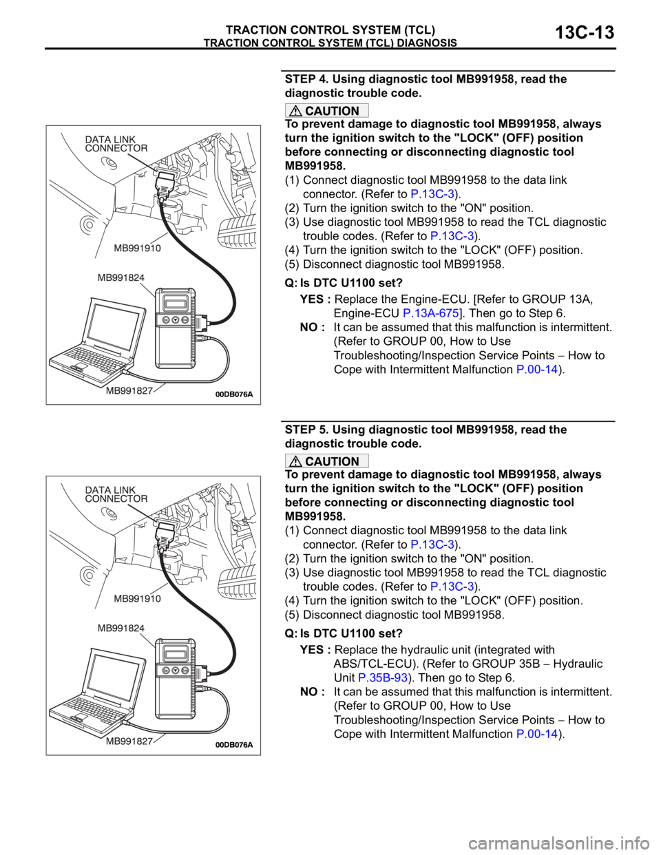
STEP 4. Using diagnostic tool MB991958, read the
diagnostic trouble code.
To prevent damage to diagnostic tool MB991958, always
turn the ignition switch to the "LOCK" (OFF) position
before connecting or disconnecting diagnostic tool
MB991958.
(1) Connect diagnostic tool MB991958 to the data link
connector. (Refer to P.13C-3).
(2) Turn the ignition switch to the "ON" position.
(3) Use diagnostic tool MB991958 to read the TCL diagnostic
trouble codes. (Refer to P.13C-3).
(4) Turn the ignition switch to the "LOCK" (OFF) position.
(5) Disconnect diagnostic tool MB991958.
Q: Is DTC U1100 set?
YES : Replace the Engine-ECU. [Refer to GROUP 13A,
Engine-ECU P.13A-675]. Then go to Step 6.
NO : It can be assumed that this malfunction is intermittent.
(Refer to GROUP 00, How to Use
Troubleshooting/Inspection Service Points
How to
Cope with Intermittent Malfunction P.00-14).
STEP 5. Using diagnostic tool MB991958, read the
diagnostic trouble code.
To prevent damage to diagnostic tool MB991958, always
turn the ignition switch to the "LOCK" (OFF) position
before connecting or disconnecting diagnostic tool
MB991958.
(1) Connect diagnostic tool MB991958 to the data link
connector. (Refer to P.13C-3).
(2) Turn the ignition switch to the "ON" position.
(3) Use diagnostic tool MB991958 to read the TCL diagnostic
trouble codes. (Refer to P.13C-3).
(4) Turn the ignition switch to the "LOCK" (OFF) position.
(5) Disconnect diagnostic tool MB991958.
Q: Is DTC U1100 set?
YES : Replace the hydraulic unit (integrated with
ABS/TCL-ECU). (Refer to GROUP 35B
Hydraulic
Unit P.35B-93). Then go to Step 6.
NO : It can be assumed that this malfunction is intermittent.
(Refer to GROUP 00, How to Use
Troubleshooting/Inspection Service Points
How to
Cope with Intermittent Malfunction P.00-14).