Page 1323 of 1500
TRACTION CONTROL SYSTEM (TCL) DIAGNOSIS
TRACTION CONTROL SYSTEM (TCL)13C-44
Connect oscilloscope to FL sensor signal terminal (5) at
ABS-ECU (A-02)
Connect oscilloscope to FR sensor signal terminal (10)
at ABS-ECU (A-02)
Connect oscilloscope to RL sensor signal terminal (17)
at ABS-ECU (A-02)
Connect oscilloscope to RR sensor signal terminal (19)
at ABS-ECU (A-02)
(7) Recommended Oscilloscope setting:
Y-axis: 2Volts
X-axis: 100ms
(8) Turn the ignition switch to the "ON" position.
(9) Turn wheel by hand at approximately 1 revolution per
second (r/sec) or drive on brake dynamometer at 5km/h.
The measurement reading of the active wheel speed sen-
sors on the oscilloscope should correspond to figure 3
below.
NOTE: If the oscilloscope signal shape is correct and wheel
sensor air gap is within specification, but the voltage values are
either higher or lower as shown in the table below, the wheel
speed sensor must be changed.
Page 1328 of 1500
TCL SWITCH
TRACTION CONTROL SYSTEM (TCL)13C-49
TCL SWITCH
REMOVAL AND INSTALLATIONM1136001600027
WHEEL SPEED SENSOR
REMOVAL AND INSTALLATIONM1136002500023
Refer to GROUP 35B, Wheel Speed Sensor P.35B-95.
ABS/TCL-ECU
REMOVAL AND INSTALLATIONM1136005300017
Replace the hydraulic unit (integrated with ABS/TCL-ECU). (Refer to GROUP 35B, Hydraulic Unit P.35B-93).
REMOVAL STEPS
HOOD LOCK RELEASE HANDLE
(REFER TO GROUP 42, HOOD P.42-8.)
INSTRUMENT LOWER PANEL (REFER
TO GROUP 52A, INSTRUMENT PANEL
ASSEMBLY P.52A-4.)
INSTRUMENT PANEL GARNISH
(REFER TO GROUP 52A,
INSTRUMENT PANEL ASSEMBLY
P.52A-4.)
1. SWITCH BEZEL ASSEMBLY
2. SWITCH PANEL ASSEMBLY
3. TCL SWITCH REMOVAL STEPS (Continued)
Page 1329 of 1500
ABS/TCL-ECU
TRACTION CONTROL SYSTEM (TCL)13C-50
Page 1419 of 1500

GENERAL DESCRIPTION
FRONT AXLE26-2
GENERAL DESCRIPTIONM1261000100370
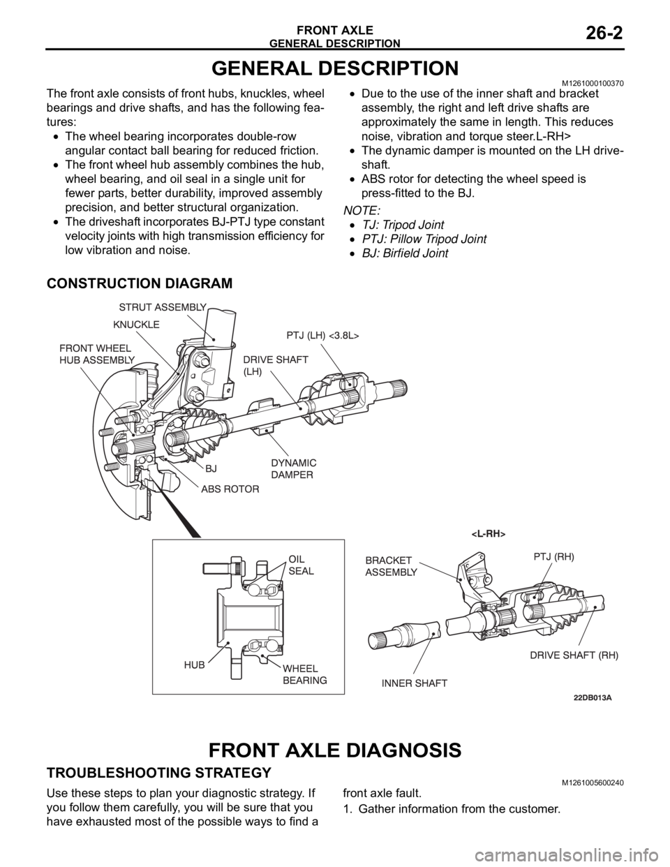
The front axle consists of front hubs, knuckles, wheel
bearings and drive shafts, and has the following fea-
tures:
The wheel bearing incorporates double-row
angular contact ball bearing for reduced friction.
The front wheel hub assembly combines the hub,
wheel bearing, and oil seal in a single unit for
fewer parts, better durability, improved assembly
precision, and better structural organization.
The driveshaft incorporates BJ-PTJ type constant
velocity joints with high transmission efficiency for
low vibration and noise.
Due to the use of the inner shaft and bracket
assembly, the right and left drive shafts are
approximately the same in length. This reduces
noise, vibration and torque steer.L-RH>
The dynamic damper is mounted on the LH drive-
shaft.
ABS rotor for detecting the wheel speed is
press-fitted to the BJ.
NOTE: .
TJ: Tripod Joint
PTJ: Pillow Tripod Joint
BJ: Birfield Joint
CONSTRUCTION DIAGRAM
FRONT AXLE DIAGNOSIS
TROUBLESHOOTING STRATEGYM1261005600240
Use these steps to plan your diagnostic strategy. If
you follow them carefully, you will be sure that you
have exhausted most of the possible ways to find a front axle fault.
1. Gather information from the customer.
Page 1426 of 1500
Page 1430 of 1500

DRIVE SHAFT ASSEMBLY
FRONT AXLE26-13
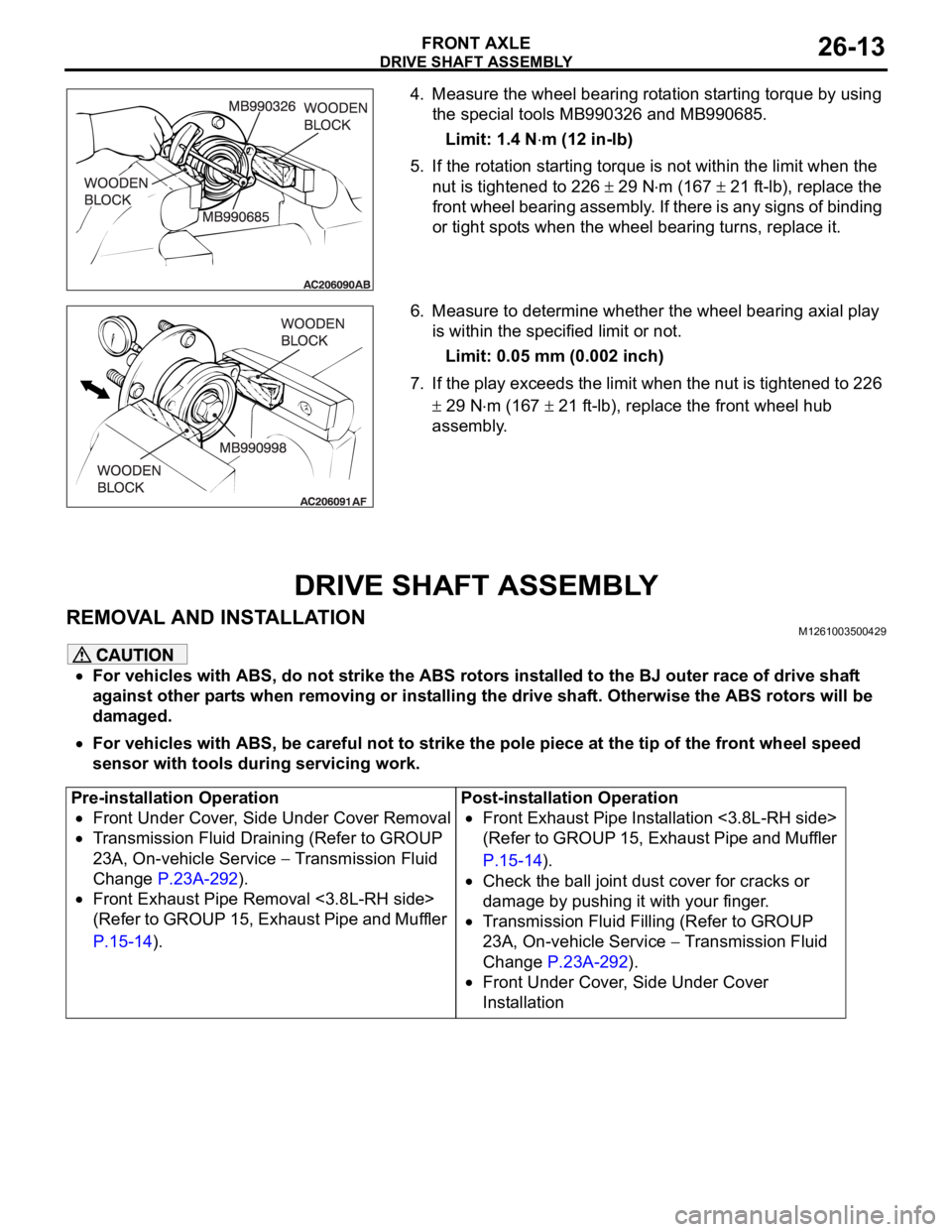
4. Measure the wheel bearing rotation starting torque by using
the special tools MB990326 and MB990685.
Limit: 1.4 N
m (12 in-lb)
5. If the rotation starting torque is not within the limit when the
nut is tightened to 226
29 Nm (167 21 ft-lb), replace the
front wheel bearing assembly. If there is any signs of binding
or tight spots when the wheel bearing turns, replace it.
6. Measure to determine whether the wheel bearing axial play
is within the specified limit or not.
Limit: 0.05 mm (0.002 inch)
7. If the play exceeds the limit when the nut is tightened to 226
29 Nm (167 21 ft-lb), replace the front wheel hub
assembly.
DRIVE SHAFT ASSEMBLY
REMOVAL AND INSTALLATIONM1261003500429
For vehicles with ABS, do not strike the ABS rotors installed to the BJ outer race of drive shaft
against other parts when removing or installing the drive shaft. Otherwise the ABS rotors will be
damaged.
For vehicles with ABS, be careful not to strike the pole piece at the tip of the front wheel speed
sensor with tools during servicing work.
Pre-installation Operation
Front Under Cover, Side Under Cover Removal
Transmission Fluid Draining (Refer to GROUP
23A, On-vehicle Service
Transmission Fluid
Change P.23A-292).
Front Exhaust Pipe Removal <3.8L-RH side>
(Refer to GROUP 15, Exhaust Pipe and Muffler
P.15-14).Post-installation Operation
Front Exhaust Pipe Installation <3.8L-RH side>
(Refer to GROUP 15, Exhaust Pipe and Muffler
P.15-14).
Check the ball joint dust cover for cracks or
damage by pushing it with your finger.
Transmission Fluid Filling (Refer to GROUP
23A, On-vehicle Service
Transmission Fluid
Change P.23A-292).
Front Under Cover, Side Under Cover
Installation
Page 1431 of 1500
Page 1435 of 1500