Page 872 of 1500
Page 874 of 1500
REFRIGERANT LINE
HEATER, AIR CONDITIONING AND VENTILATION55-173
O-RING REPLACEMENT
1.Removal- use a wooden toothpick or plastic awl to remove
o-ring without damaging the tube.
2.Installation- lubricate o-ring with ND-Oil 8, roll the
new o-ring into captured position.
.
PIPE JOINT PRECAUTIONS
1. Before making any hose and tube connections, always
apply ND-Oil 8 compressor oil to o-ring.
Avoid applying oil in areas with acrylic resin or ABS plastic
as it causes enviromental stress cracking to these resins.
2. Ensure the connecting parts are free of foreign material.
Page 887 of 1500
INSPECTION TERMINAL
COMPONENT LOCATIONS70-8
INSPECTION TERMINALM1701000200354
SENSORM1701000600415
NAME SYMBOL NAME SYMBOL
A/C pressure sensor I Interior temperature sensor
A/C>S
A/T control solenoid valve assembly
(Incorporating transmission fluid
temperature sensor)N Knock sensor C
Accelerator pedal position sensor R Left bank heated oxygen sensor (front)
<3.8L Engine>P
Air thermo sensor T Left bank heated oxygen sensor (rear)
<3.8L Engine>P
Ambient temperature sensor L Manifold absolute pressure sensor B
Camshaft position sensor D Mass airflow sensor G
Crankshaft position sensor A Sunroof assembly (Incorporating pulse
sensor)U
Fuel pump module (Incorporating fuel
level sensor (main) and fuel tank
temperature sensor)W Output shaft speed sensor H
Fuel level sensor (sub) V Photo sensor Q
Right bank heated oxygen sensor
(front) <3.8L Engine>O
Input shaft speed sensor K Right bank heated oxygen sensor (rear)
<3.8L Engine>O
Page 888 of 1500
SENSOR
COMPONENT LOCATIONS70-9
NOTE: The * symbols indicate equipped at both sides.Engine coolant temperature sensor F Throttle body assembly (Incorporating
throttle position sensor)E
Front impact sensor M Wheel speed sensor (front) Y
Side impact sensor a Wheel speed sensor (rear) b NAME SYMBOL NAME SYMBOL
Page 893 of 1500
CONTROL UNIT
COMPONENT LOCATIONS70-14
CONTROL UNITM1701000700360
NAME SYMBOL NAME SYMBOL
ABS-ECU or ABS/TCL-ECU A Multi center display unit F
A/C-ECU J Engine-ECU B
Column switch (incorporating
column-ECU)D Power window main switch
(incorporating CPU)M
Combination meter (incorporating CPU) E SRS-ECU I
ETACS-ECU G Sunroof assembly (incorporating
sunroof-ECU)K
Front-ECU C A/T-ECU L
Page 896 of 1500
SOLENOID AND SOLENOID VALVE
COMPONENT LOCATIONS70-17
SOLENOID AND SOLENOID VALVEM1701000800378
NAME SYMBOL NAME SYMBOL
A/T control solenoid valve assembly E
Evaporative emission purge solenoid B Hydraulic unit (incorporating ABS
solenoid valve)A
Page 917 of 1500

GENERAL DESCRIPTION
ENGINE COOLING14-2
GENERAL DESCRIPTIONM1141000100401
The cooling system is designed to keep every
part of the engine at appropriate temperature in
whatever condition the engine may be operated.
The cooling method is of the water-cooled, pres-
sure forced circulation type in which the water
pump pressurizes coolant and circulates it
throughout the engine. If the coolant temperature exceeds the prescribed temperature, the thermo-
stat opens to circulate the coolant through the
radiator as well so that the heat absorbed by the
coolant may be radiated into the air. The water
pump is of the centrifugal type and is driven by
the drive belt from the crankshaft. The radiator is
the corrugated fin, down flow type.
SPECIAL TOOLM1141000600279
ENGINE COOLING DIAGNOSIS
INTRODUCTIONM1141005300347
The system cools the engine so that it does not over-
heat and maintains the engine at an optimum tem-
perature. The system components are the radiator,
water pump, thermostat, condenser and fan assem-
blies. Possible faults include low coolant, contamina-
tion, belt loosening and component damage.
TROUBLESHOOTING STRATEGYM1141005200340
Use these steps to plan your diagnostic strategy. If
you follow them carefully, you will be sure to find
most of the engine cooling faults.
1. Gather information from the customer.2. Verify that the condition described by the
customer exists.
3. Find and repair the malfunction by following the
SYMPTOM CHART.
4. Verify that the malfunction is eliminated. TOOL TOOL NUMBER AND
NAMESUPERSESSION APPLICATION
MB991871
LLC changerGeneral service tool Coolant refilling
Page 950 of 1500

THERMOSTAT
ENGINE COOLING14-35
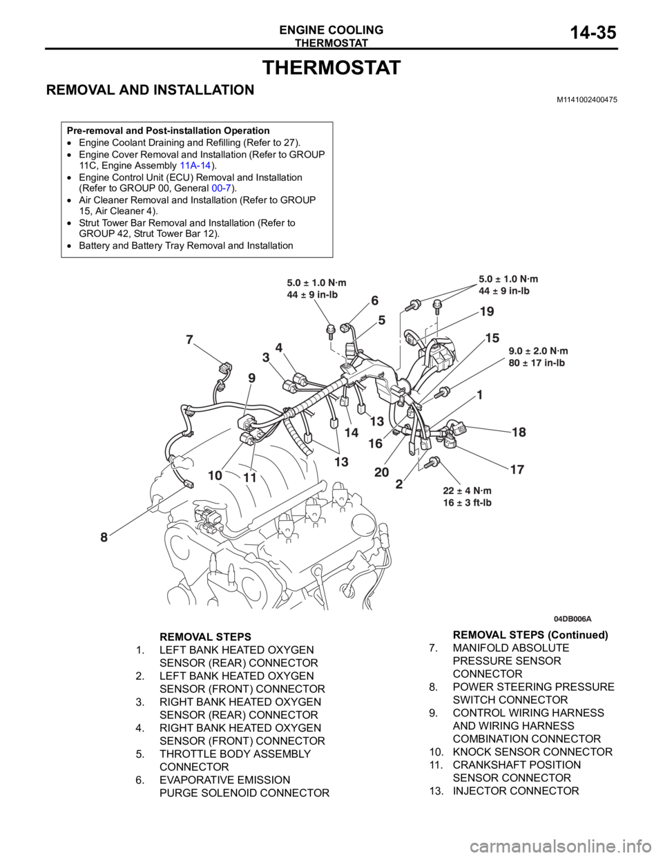
THERMOSTAT
REMOVAL AND INSTALLATIONM1141002400475
Pre-removal and Post-installation Operation
Engine Coolant Draining and Refilling (Refer to 27).
Engine Cover Removal and Installation (Refer to GROUP
11C, Engine Assembly 11A-14).
Engine Control Unit (ECU) Removal and Installation
(Refer to GROUP 00, General 00-7).
Air Cleaner Removal and Installation (Refer to GROUP
15, Air Cleaner 4).
Strut Tower Bar Removal and Installation (Refer to
GROUP 42, Strut Tower Bar 12).
Battery and Battery Tray Removal and Installation
REMOVAL STEPS
1. LEFT BANK HEATED OXYGEN
SENSOR (REAR) CONNECTOR
2. LEFT BANK HEATED OXYGEN
SENSOR (FRONT) CONNECTOR
3. RIGHT BANK HEATED OXYGEN
SENSOR (REAR) CONNECTOR
4. RIGHT BANK HEATED OXYGEN
SENSOR (FRONT) CONNECTOR
5. THROTTLE BODY ASSEMBLY
CONNECTOR
6. EVAPORATIVE EMISSION
PURGE SOLENOID CONNECTOR7. MANIFOLD ABSOLUTE
PRESSURE SENSOR
CONNECTOR
8. POWER STEERING PRESSURE
SWITCH CONNECTOR
9. CONTROL WIRING HARNESS
AND WIRING HARNESS
COMBINATION CONNECTOR
10. KNOCK SENSOR CONNECTOR
11. CRANKSHAFT POSITION
SENSOR CONNECTOR
13. INJECTOR CONNECTORREMOVAL STEPS (Continued)