Page 952 of 1500
Page 965 of 1500

INTAKE MANIFOLD PLENUM
INTAKE AND EXHAUST15-6
Required Special Tool:
MD998412: Guide
INSTALLATION SERVICE POINT
.
>>A<< INTAKE MANIFOLD PLENUM INSTALLA-
TION
Use special tool MD998412 to install the intake manifold ple-
num.
REMOVAL STEPS
1. MANIFOLD ABSOLUTE
PRESSURE SENSOR
CONNECTOR
2. CONTROL WIRING HARNESS
AND INJECTOR WIRING
HARNESS COMBINATION
CONNECTOR
3. CRANKSHAFT POSITION
SENSOR CONNECTOR
4. KNOCK SENSOR CONNECTOR
5. POWER STEERING PRESSURE
SWITCH CONNECTOR
6. EVAPORATIVE EMISSION
PURGE SOLENOID CONNECTOR
8. VACUUM HOSE CONNECTION
9. PURGE HOSE
10. POWER STEERING PRESSURE
HOSE CLAMP
11. POWER STEERING PRESSURE
HOSE CLAMP BRACKET
12. INTAKE MANIFOLD PLENUM
STAY, REARSTEERING GEAR AND LINKAGE
PROTECTOR (REFER TO 37,
STEERING GEAR BOX AND
LINKAGE P.37-30)
POWER STEERING OIL PUMP
(REFER TO 37, POWER
STEERING OIL PUMP ASSEMBLY
P.37-43)
15. POWER STEERING OIL PUMP
BRACKET CONNECTING BOLT
16. INTAKE MANIFOLD PLENUM
STAY, FRONT
>>A<<17. INTAKE MANIFOLD PLENUM
18. INTAKE MANIFOLD PLENUM
GASKET
19. VACUUM PIPE
20. EVAPORATIVE EMISSION
PURGE SOLENOID ASSEMBLY
23. HARNESS BRACKET
24. MANIFOLD ABSOLUTE
PRESSURE SENSOR
25. O-RINGREMOVAL STEPS (Continued)
Page 977 of 1500
SPECIFICATIONS
INTAKE AND EXHAUST15-18
SERVICE SPECIFICATIONM1151000300462
SEALANTSM1151000500187
Intake manifold plenum
Evaporative emission purge solenoid bolt 9.0
1.0 Nm (80 9 in-lb)
Harness bracket bolt 11
1 Nm (98 8 in-lb)
Intake manifold plenum bolt 18
2 Nm (13 2 ft-lb)
Intake manifold plenum stay bolt M8 18
2 Nm (13 2 ft-lb)
M10 36
6 Nm (27 4 ft-lb)
Manifold absolute pressure sensor bolt 5.0
1.0 Nm (44 9 in-lb)
Power steering pressure hose clamp nut 12
2 Nm (102 22 in-lb)
Power steering pressure hose clamp bracket bolt 12
2 Nm (102 22 in-lb)
Power steering oil pump bracket connecting bolt 41
8 Nm (30 6 ft-lb) ITEMSPECIFICATION
ITEM STANDARD VALUE LIMIT
Manifold distortion of the installation surface mm (in) 0.15 (0.006) or less 0.20 (0.008)
ITEM SPECIFIED SEALANT
Thermostat case assembly 3M
AAD Part No.8672, 3M AAD Part No.8679/8678 or
equivalent
Thermostat case assembly bolt 3M
AAD Part No. 8730, 8731 or equivalent
Page 1086 of 1500

WINDOW GLASS
BODY42-19
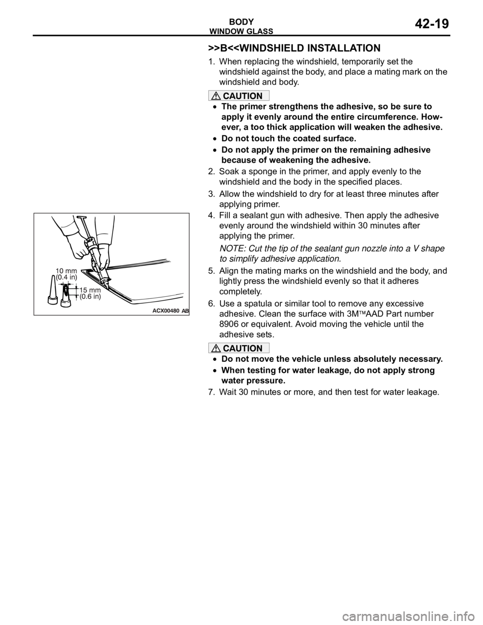
>>B<
1. When replacing the windshield, temporarily set the
windshield against the body, and place a mating mark on the
windshield and body.
The primer strengthens the adhesive, so be sure to
apply it evenly around the entire circumference. How-
ever, a too thick application will weaken the adhesive.
Do not touch the coated surface.
Do not apply the primer on the remaining adhesive
because of weakening the adhesive.
2. Soak a sponge in the primer, and apply evenly to the
windshield and the body in the specified places.
3. Allow the windshield to dry for at least three minutes after
applying primer.
4. Fill a sealant gun with adhesive. Then apply the adhesive
evenly around the windshield within 30 minutes after
applying the primer.
NOTE: Cut the tip of the sealant gun nozzle into a V shape
to simplify adhesive application.
5. Align the mating marks on the windshield and the body, and
lightly press the windshield evenly so that it adheres
completely.
6. Use a spatula or similar tool to remove any excessive
adhesive. Clean the surface with 3M
AAD Part number
8906 or equivalent. Avoid moving the vehicle until the
adhesive sets.
Do not move the vehicle unless absolutely necessary.
When testing for water leakage, do not apply strong
water pressure.
7. Wait 30 minutes or more, and then test for water leakage.
Page 1164 of 1500
35-1
GROUP 35
SERVICE BRAKES
CONTENTS
BASIC BRAKE SYSTEM . . . . . . . . . . . . . . . . . . . . . . . . . . . . . .35A
ANTI-LOCK BRAKING SYSTEM (ABS). . . . . . . . . . . . . . . . . . .35B
Page 1167 of 1500

GENERAL DESCRIPTION
BASIC BRAKE SYSTEM35A-2
GENERAL DESCRIPTIONM1351000100440
The brake system has been designed to give greater
reliability and durability and to provide excellent brak-
ing performance.
FEATURES
.
Improved braking performance
1. An 8+9 inch tandem brake booster provides suffi-
cient braking force in sudden braking range.
2. 296mm front ventilated disc brakes provide sta-
ble braking force and improved braking feel.
3. 303mm rear ventillated disc brakes are used.
.
Improved stability
1. A 4-wheel anti-lock braking system (4ABS) pre-
vents slipping caused by the vehicle wheels lock-
ing up, in order to maintain a stable vehicle
posture and steering performance.
2. An electronic brake-force distribution (EBD)
makes it possible to maintain the maximum
amount of braking force even when the vehicle's
load is unevenly distributed. 3. Front- and rear-wheel X-type brake line layout
are used.
4. Ventilated discs brakes improve anti-fading per-
formance.
.
Improved serviceability
1. A diagnosis function for the ABS system makes
inspection easier.
2. An outer disc separated hub and rotor make
removal and installation easier.
3. The master cylinder reservoir is utilised for both
brake and clutch fluid on manual transmission
vehicles.
4. The master cylinder filter is coloured black for
improved viewing.
5. The ABS-ECU and hydraulic unit are integrated
to make them more compact and light weight.
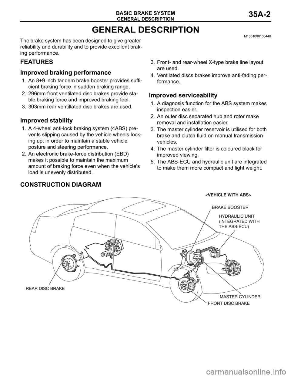
CONSTRUCTION DIAGRAM
Page 1170 of 1500

BASIC BRAKE SYSTEM DIAGNOSIS
BASIC BRAKE SYSTEM35A-5
STEP 4. Check for pinched or restricted brake
tube or hose.
Q: Is there a pinched or restricted brake tube or hose?
YES :
Replace that complete section of brake tube
or brake hose. Then go to Step 7.
NO : Go to Step 5.
STEP 5. Check for oil, water, etc., on the pad
contact surfaces of all brakes.
Q: Is oil, water, etc., on the pad contact surface?
YES :
Replace the part and determine the
source/cause of foreign material. Recheck
symptom. Then go to Step 7.
NO : The procedure is complete. If condition
persists for vehicles without ABS, go to Step
6.
STEP 7. Recheck symptom.
Q: Is the symptom eliminated?
YES :
The procedure is complete.
NO : Start over at step 1. If a new symptom
surfaces, refer to the appropriate symptom
chart.
INSPECTION PROCEDURE 3: Increased Pedal Stroke (Reduced Pedal-to-Floor Board Clearance)
.
DIAGNOSIS
STEP 1. Check for spongy (not firm) brakes.
(1) With engine not running, depress the brake pedal
rapidly several times to deplete booster vacuum
reserve.
(2) With the brake pedal fully released, depress the
brake pedal slowly until it stops.
(3) With a measuring device (ruler, etc.) next to the
brake pedal, depress the pedal firmly and
measure the distance the pedal traveled.
Q: Is the distance greater than 20 mm (0.8 inch)?
YES :
Bleed the brakes to remove air in the fluid
(Refer to P.35A-16). Then go to Step 7.
NO : Go to Step 2.
STEP 2. Check the pad for wear.
Refer to P.35A-17.
Q: Is the pad thickness outside of specifications?
YES :
Replace the part. Then go to Step 7.
NO : Go to Step 3.
STEP 3. Check the vacuum hose and check valve
for damage.
Refer to P.35A-15.
Q: Is there a damage?
YES :
Replace the part. Then go to Step 7.
NO : Go to Step 4.
STEP 4. Check the master cylinder function.
Refer to P.35A-23.
Q: Is there a fault?
YES :
Repair it. Then go to Step 7.
NO : Go to Step 5.
STEP 5. Check for brake fluid leaks.
Q: Is there a leak?
YES :
Check the connection for looseness,
corrosion, etc. Clean and repair as
necessary. If leaking in any tube or hose
section, replace the complete tube or hose.
Then go to Step 7 .
NO : Go to Step 6.
STEP 6. Check for excessive clearance between
the push rod and primary piston.
Refer to P.35A-26.
Q: Is the clearance outside of specifications?
YES :
Adjust the clearance. Then go to Step 7.
NO : Go to Step 7.
STEP 7. Recheck symptom.
Q: Is the symptom eliminated?
YES :
The procedure is complete.
NO : Start over at step 1. If a new symptom
surfaces, refer to the symptom chart.
Page 1193 of 1500