2005 MITSUBISHI 380 Exhaust
[x] Cancel search: ExhaustPage 1090 of 1500
DOOR
BODY42-23
DOOR
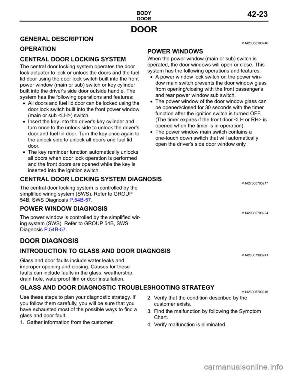
GENERAL DESCRIPTIONM1423000100246
OPERATION
.
CENTRAL DOOR LOCKING SYSTEM
The central door locking system operates the door
lock actuator to lock or unlock the doors and the fuel
lid door using the door lock switch built into the front
power window (main or sub) switch or key cylinder
built into the driver's side door outside handle. The
system has the following operations and features:
All doors and fuel lid door can be locked using the
door lock switch built into the front power window
(main or sub
Insert the key into the driver's key cylinder and
turn once to the unlock side to unlock the driver's
door and fuel lid door. Turn the key once again to
the unlock side to unlock all doors and fuel lid
door.
The key reminder function automatically unlocks
all doors when door lock operation is performed
and the front doors are opened while the key is
inserted into the ignition switch.
.
POWER WINDOWS
When the power window (main or sub) switch is
operated, the door windows will open or close. This
system has the following operations and features:
A power window lock switch on the power win-
dow main switch prevents the door window glass
from opening/closing with the front passenger's
and rear power window sub switch.
The power window of the door window glass can
be opened/closed for 30 seconds with the timer
function after the ignition switch is turned OFF.
(The timer expires if the front door
opened when the timer is in operation).
The power window main switch contains a
one-touch down switch that will automatically
open the driver's side door window only.
CENTRAL DOOR LOCKING SYSTEM DIAGNOSISM1427000700217
The central door locking system is controlled by the
simplified wiring system (SWS). Refer to GROUP
54B, SWS Diagnosis P.54B-57.
POWER WINDOW DIAGNOSISM1429000700224
The power window is controlled by the simplified wir-
ing system (SWS). Refer to GROUP 54B, SWS
Diagnosis P.54B-57.
DOOR DIAGNOSIS
INTRODUCTION TO GLASS AND DOOR DIAGNOSISM1423007300241
Glass and door faults include water leaks and
improper opening and closing. Causes for these
faults can include faults in the glass, weatherstrip,
drain hole, waterproof film or door installation.
GLASS AND DOOR DIAGNOSTIC TROUBLESHOOTING STRATEGYM1423006700246
Use these steps to plan your diagnostic strategy. If
you follow them carefully, you will be sure that you
have exhausted most of the possible ways to find a
glass and door fault.
1. Gather information from the customer.2. Verify that the condition described by the
customer exists.
3. Find the malfunction by following the Symptom
Chart.
4. Verify malfunction is eliminated.
Page 1127 of 1500
TRUNK LID
BODY42-60
TRUNK LID
TRUNK LID DIAGNOSIS
INTRODUCTION TO TRUNK LID DIAGNOSISM1421005800374
Difficult locking and unlocking, uneven clearance and
height, and wind noise from the trunk lid may be
caused by improper adjustment of the trunk lid.
TRUNK LID DIAGNOSTIC TROUBLESHOOTING STRATEGYM1421005900348
Use these steps to plan your diagnostic strategy. If
you follow them carefully, you will be sure that you
have exhausted most of the possible ways to find a
trunk lid fault.
1. Gather information from the customer.2. Verify that the condition described by the
customer exists.
3. Find the malfunction by following the Symptom
Chart.
4. Verify malfunction is eliminated.
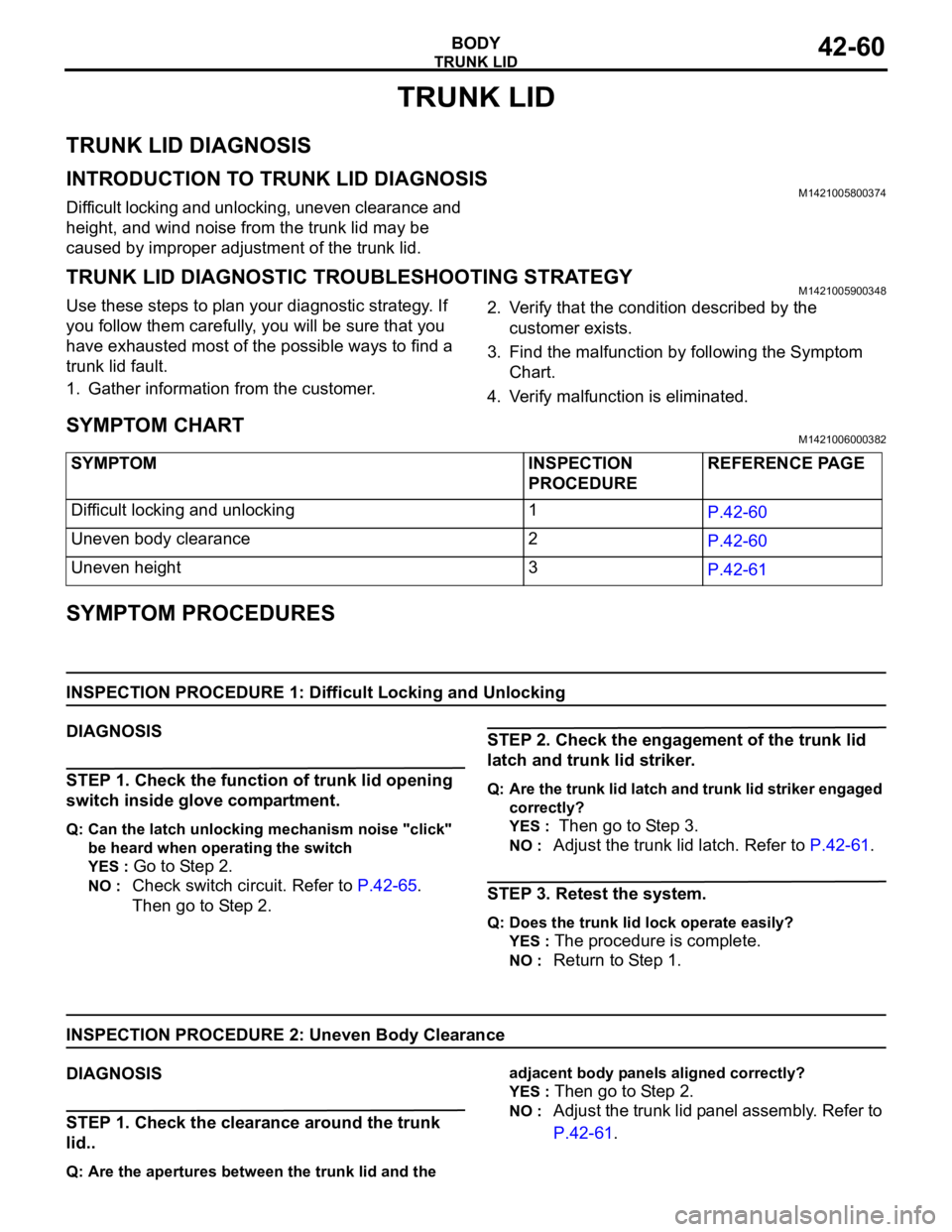
SYMPTOM CHARTM1421006000382
SYMPTOM PROCEDURES
INSPECTION PROCEDURE 1: Difficult Locking and Unlocking
DIAGNOSIS
STEP 1. Check the function of trunk lid opening
switch inside glove compartment.
Q: Can the latch unlocking mechanism noise "click"
be heard when operating the switch
YES :
Go to Step 2.
NO : Check switch circuit. Refer to P.42-65.
Then go to Step 2.
STEP 2. Check the engagement of the trunk lid
latch and trunk lid striker.
Q: Are the trunk lid latch and trunk lid striker engaged
correctly?
YES :
Then go to Step 3.
NO : Adjust the trunk lid latch. Refer to P.42-61.
STEP 3. Retest the system.
Q: Does the trunk lid lock operate easily?
YES :
The procedure is complete.
NO : Return to Step 1.
INSPECTION PROCEDURE 2: Uneven Body Clearance
DIAGNOSIS
STEP 1. Check the clearance around the trunk
lid..
Q: Are the apertures between the trunk lid and the adjacent body panels aligned correctly?
YES :
Then go to Step 2.
NO : Adjust the trunk lid panel assembly. Refer to
P.42-61. SYMPTOM INSPECTION
PROCEDUREREFERENCE PAGE
Difficult locking and unlocking 1
P.42-60
Uneven body clearance 2
P.42-60
Uneven height 3
P.42-61
Page 1168 of 1500
BASIC BRAKE SYSTEM DIAGNOSIS
BASIC BRAKE SYSTEM35A-3
BASIC BRAKE SYSTEM DIAGNOSIS
INTRODUCTION TO BASIC BRAKE SYSTEM DIAGNOSISM1351009700319
Hydraulic brakes are composed of the brake pedal,
master cylinder, brake booster and disc brakes. Mal-
functions such as insufficient braking power or the
generation of noise may occur due to wear, damage
or incorrect adjustment of these components.
BASIC BRAKE SYSTEM DIAGNOSTIC TROUBLESHOOTING STRATEGYM1351009800316
Use these steps to plan your diagnostic strategy. If
you follow them carefully, you will be sure that you
have exhausted most of the possible ways to find a
basic brake system fault.
1. Gather information from the customer.2. Verify that the condition described by the
customer exists.
3. Find the malfunction by following the symptom
chart.
4. Verify malfunction is eliminated.
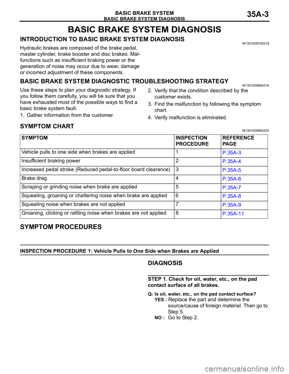
SYMPTOM CHARTM1351009900324
SYMPTOM PROCEDURES
INSPECTION PROCEDURE 1: Vehicle Pulls to One Side when Brakes are Applied
.DIAGNOSIS
STEP 1. Check for oil, water, etc., on the pad
contact surface of all brakes.
Q: Is oil, water, etc., on the pad contact surface?
YES :
Replace the part and determine the
source/cause of foreign material. Then go to
St e p 5.
NO : Go to Step 2. SYMPTOM INSPECTION
PROCEDUREREFERENCE
PA G E
Vehicle pulls to one side when brakes are applied 1
P.35A-3
Insufficient braking power 2
P.35A-4
Increased pedal stroke (Reduced pedal-to-floor board clearance)3
P.35A-5
Brake drag 4
P.35A-6
Scraping or grinding noise when brake are applied 5
P.35A-7
Squealing, groaning or chattering noise when brake are applied 6
P.35A-8
Squealing noise when brakes are not applied 7
P.35A-9
Groaning, clicking or rattling noise when brakes are not applied8
P.35A-11
Page 1209 of 1500
GENERAL DESCRIPTION
PARKING BRAKES36-2
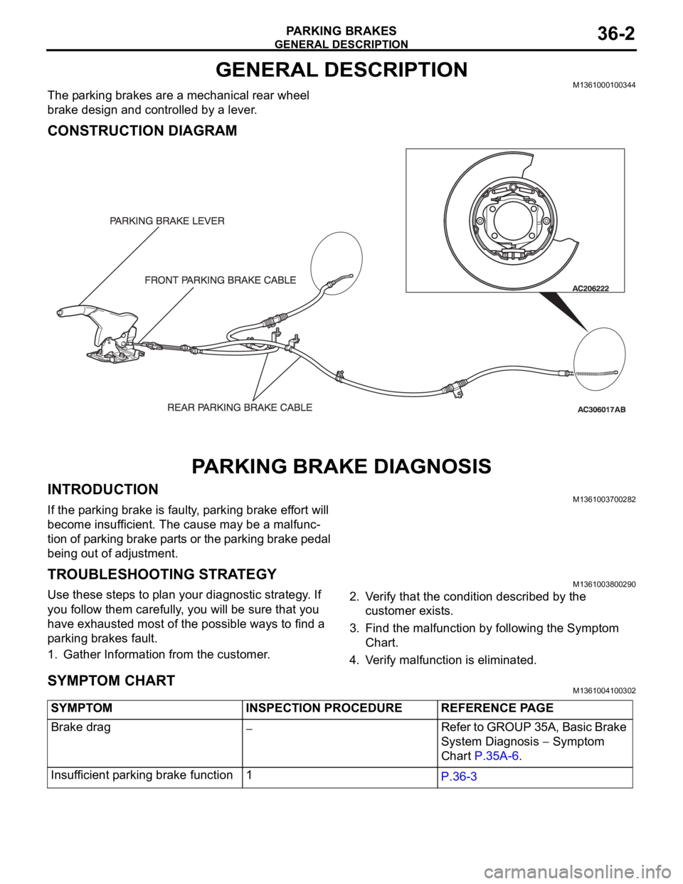
GENERAL DESCRIPTIONM1361000100344
The parking brakes are a mechanical rear wheel
brake design and controlled by a lever.
CONSTRUCTION DIAGRAM
PARKING BRAKE DIAGNOSIS
INTRODUCTIONM1361003700282
If the parking brake is faulty, parking brake effort will
become insufficient. The cause may be a malfunc-
tion of parking brake parts or the parking brake pedal
being out of adjustment.
TROUBLESHOOTING STRATEGYM1361003800290
Use these steps to plan your diagnostic strategy. If
you follow them carefully, you will be sure that you
have exhausted most of the possible ways to find a
parking brakes fault.
1. Gather Information from the customer.2. Verify that the condition described by the
customer exists.
3. Find the malfunction by following the Symptom
Chart.
4. Verify malfunction is eliminated.
SYMPTOM CHARTM1361004100302
SYMPTOM INSPECTION PROCEDURE REFERENCE PAGE
Brake drag
Refer to GROUP 35A, Basic Brake
System Diagnosis
Symptom
Chart P.35A-6.
Insufficient parking brake function 1
P.36-3
Page 1223 of 1500
GENERAL00-2
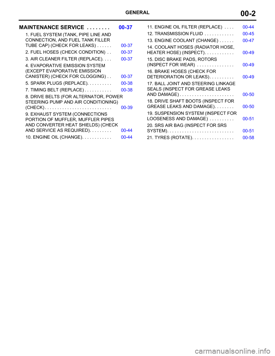
MAINTENANCE SERVICE . . . . . . . .00-37
1. FUEL SYSTEM (TANK, PIPE LINE AND
CONNECTION, AND FUEL TANK FILLER
TUBE CAP) (CHECK FOR LEAKS) . . . . . . 00-37
2. FUEL HOSES (CHECK CONDITION) . . 00-37
3. AIR CLEANER FILTER (REPLACE). . . . 00-37
4. EVAPORATIVE EMISSION SYSTEM
(EXCEPT EVAPORATIVE EMISSION
CANISTER) (CHECK FOR CLOGGING) . . 00-37
5. SPARK PLUGS (REPLACE). . . . . . . . . . 00-38
7. TIMING BELT (REPLACE) . . . . . . . . . . . 00-38
8. DRIVE BELTS (FOR ALTERNATOR, POWER
STEERING PUMP AND AIR CONDITIONING)
(CHECK) . . . . . . . . . . . . . . . . . . . . . . . . . . . 00-39
9. EXHAUST SYSTEM (CONNECTIONS
PORTION OF MUFFLER, MUFFLER PIPES
AND CONVERTER HEAT SHIELDS) (CHECK
AND SERVICE AS REQUIRED) . . . . . . . . . 00-44
10. ENGINE OIL (CHANGE) . . . . . . . . . . . . 00-4411. ENGINE OIL FILTER (REPLACE) . . . . 00-44
12. TRANSMISSION FLUID . . . . . . . . . . . . 00-45
13. ENGINE COOLANT (CHANGE) . . . . . . 00-47
14. COOLANT HOSES (RADIATOR HOSE,
HEATER HOSE) (INSPECT). . . . . . . . . . . . 00-49
15. DISC BRAKE PADS, ROTORS
(INSPECT FOR WEAR) . . . . . . . . . . . . . . . 00-49
16. BRAKE HOSES (CHECK FOR
DETERIORATION OR LEAKS) . . . . . . . . . . 00-49
17. BALL JOINT AND STEERING LINKAGE
SEALS (INSPECT FOR GREASE LEAKS
AND DAMAGE) . . . . . . . . . . . . . . . . . . . . . . 00-50
18. DRIVE SHAFT BOOTS (INSPECT FOR
GREASE LEAKS AND DAMAGE) . . . . . . . . 00-50
19. SUSPENSION SYSTEM (INSPECT FOR
LOOSENESS AND DAMAGE) . . . . . . . . . . 00-51
20. SRS AIR BAG (INSPECT FOR SRS
SYSTEM). . . . . . . . . . . . . . . . . . . . . . . . . . . 00-51
21. TYRES (ROTATE). . . . . . . . . . . . . . . . . 00-58
Page 1259 of 1500
MAINTENANCE SERVICE
GENERAL00-38
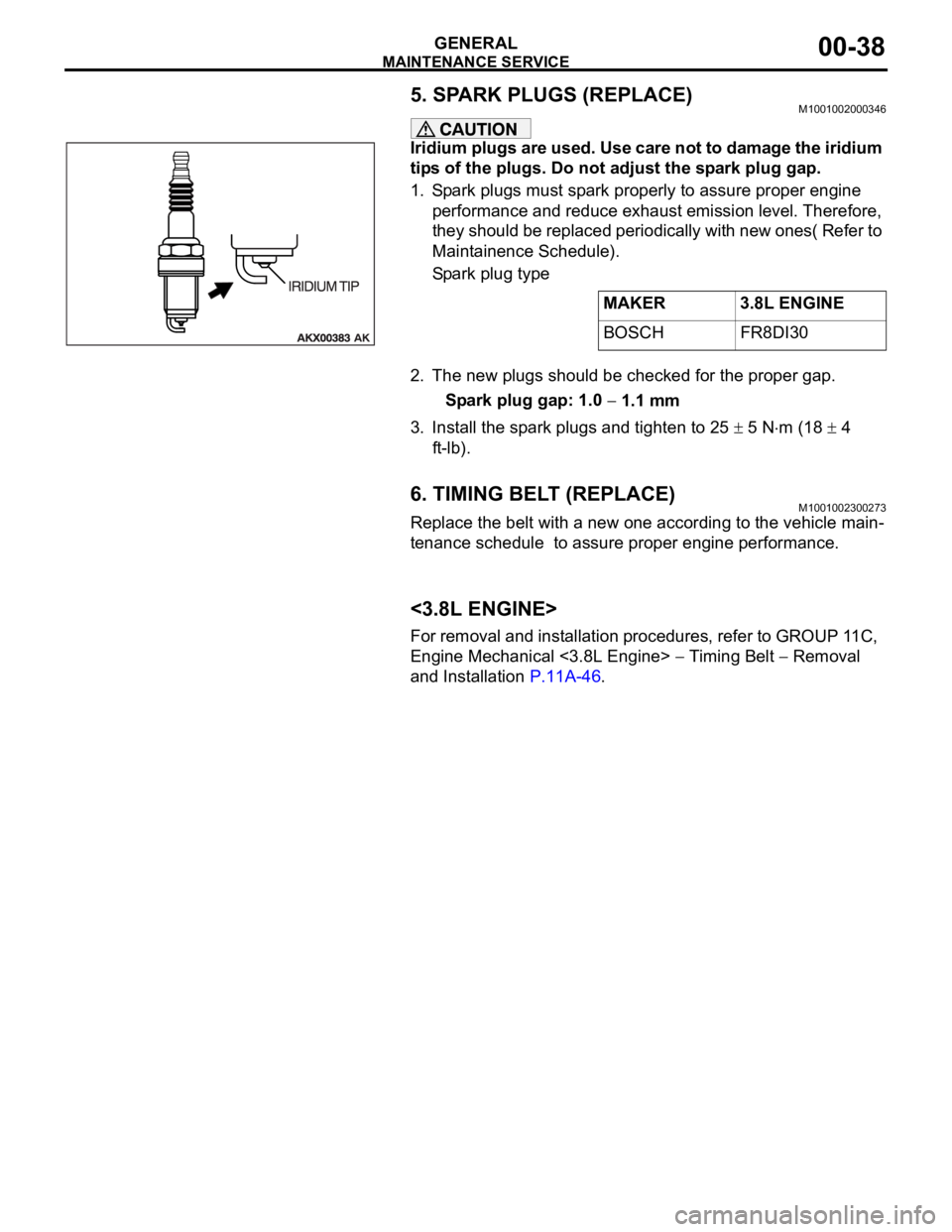
5. SPARK PLUGS (REPLACE)M1001002000346
Iridium plugs are used. Use care not to damage the iridium
tips of the plugs. Do not adjust the spark plug gap.
1. Spark plugs must spark properly to assure proper engine
performance and reduce exhaust emission level. Therefore,
they should be replaced periodically with new ones( Refer to
Maintainence Schedule).
Spark plug type
2. The new plugs should be checked for the proper gap.
Spark plug gap: 1.0
1.1 mm
3. Install the spark plugs and tighten to 25
5 Nm (18 4
ft-lb).
6. TIMING BELT (REPLACE)M1001002300273
Replace the belt with a new one according to the vehicle main-
tenance schedule to assure proper engine performance.
<3.8L ENGINE>
For removal and installation procedures, refer to GROUP 11C,
Engine Mechanical <3.8L Engine>
Timing Belt Removal
and Installation P.11A-46.MAKER 3.8L ENGINE
BOSCH FR8DI30
Page 1265 of 1500
MAINTENANCE SERVICE
GENERAL00-44
8. EXHAUST SYSTEM (CONNECTIONS PORTION
OF MUFFLER, MUFFLER PIPES AND
CONVERTER HEAT SHIELDS) (CHECK AND
SERVICE AS REQUIRED)
M1001005800299
1. Check for holes and exhaust gas leaks due to damage,
corrosion, etc.
2. Check the joints and connections for looseness and exhaust
gas leaks.
3. Check the rubber hangers and brackets for damage.
9. ENGINE OIL (CHANGE)M1001002600360
Use the specified oil. (Refer to P.00-35.)
Use care as oil could be hot.
1. After warming up the engine, remove the oil filler cap.
2. Remove the drain plug to allow the engine oil to drain.
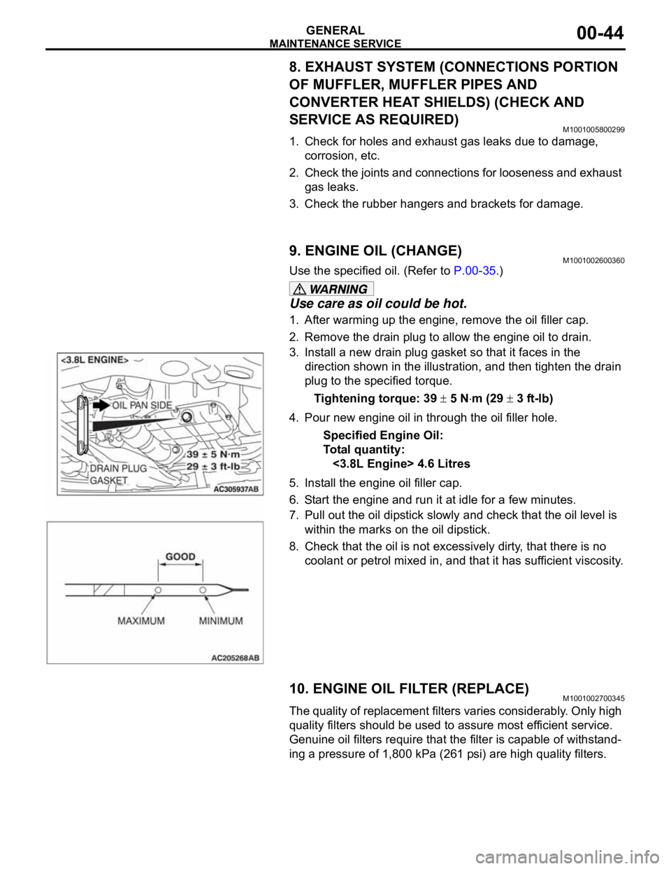
3. Install a new drain plug gasket so that it faces in the
direction shown in the illustration, and then tighten the drain
plug to the specified torque.
Tightening torque: 39
5 Nm (29 3 ft-lb)
4. Pour new engine oil in through the oil filler hole.
Specified Engine Oil:
To ta l q u a n t i t y :
<3.8L Engine> 4.6 Litres
5. Install the engine oil filler cap.
6. Start the engine and run it at idle for a few minutes.
7. Pull out the oil dipstick slowly and check that the oil level is
within the marks on the oil dipstick.
8. Check that the oil is not excessively dirty, that there is no
coolant or petrol mixed in, and that it has sufficient viscosity.
10. ENGINE OIL FILTER (REPLACE)M1001002700345
The quality of replacement filters varies considerably. Only high
quality filters should be used to assure most efficient service.
Genuine oil filters require that the filter is capable of withstand-
ing a pressure of 1,800 kPa (261 psi) are high quality filters.
.
Page 1334 of 1500
ENGINE CONTROL
ENGINE AND EMISSION CONTROL17-3
ENGINE CONTROL
GENERAL DESCRIPTIONM1171000100437
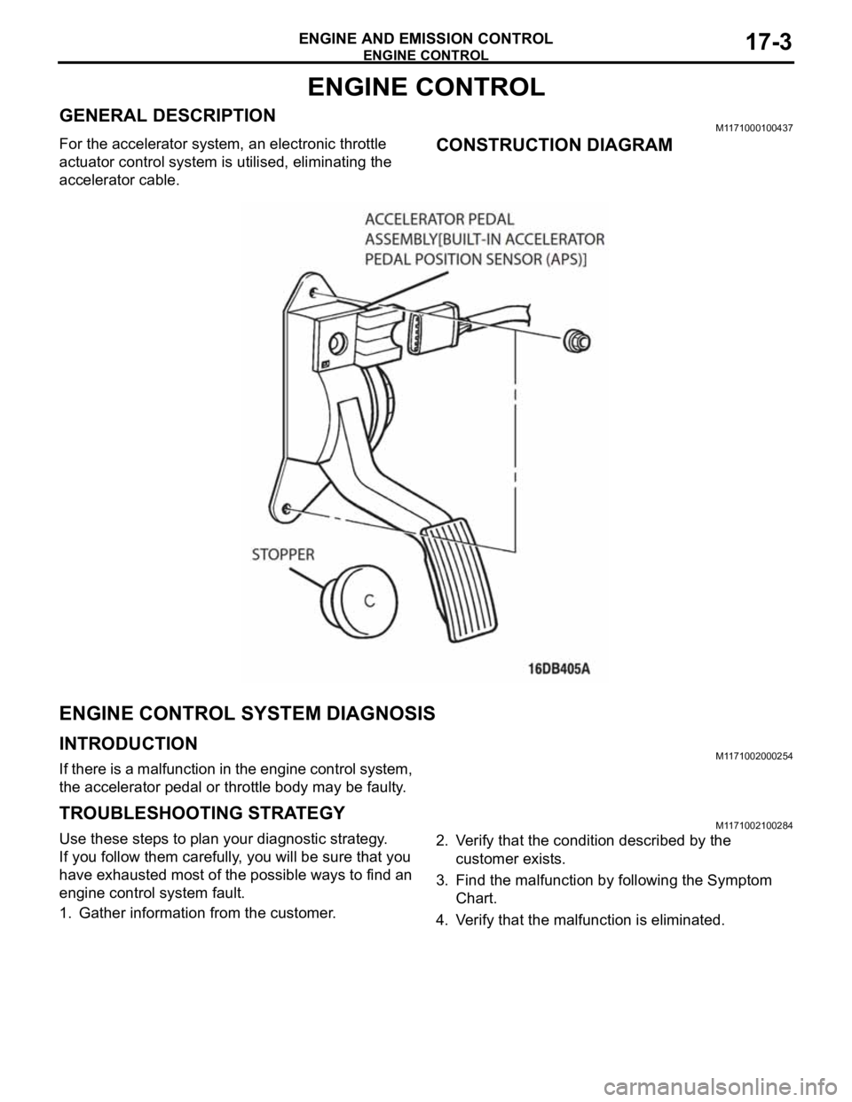
For the accelerator system, an electronic throttle
actuator control system is utilised, eliminating the
accelerator cable.CONSTRUCTION DIAGRAM
ENGINE CONTROL SYSTEM DIAGNOSIS
INTRODUCTIONM1171002000254
If there is a malfunction in the engine control system,
the accelerator pedal or throttle body may be faulty.
TROUBLESHOOTING STRATEGYM1171002100284
Use these steps to plan your diagnostic strategy.
If you follow them carefully, you will be sure that you
have exhausted most of the possible ways to find an
engine control system fault.
1. Gather information from the customer.2. Verify that the condition described by the
customer exists.
3. Find the malfunction by following the Symptom
Chart.
4. Verify that the malfunction is eliminated.