Page 973 of 1500
Page 974 of 1500
EXHAUST PIPE AND MAIN MUFFLER
INTAKE AND EXHAUST15-15
INSTALLATION SERVICE POINT
.
>>A<< HEATED OXYGEN SENSOR INSTALLA-
TION
Use special tool MB991953 to install the heated oxygen sensor.
Page 975 of 1500

SPECIFICATIONS
INTAKE AND EXHAUST15-16
SPECIFICATIONS
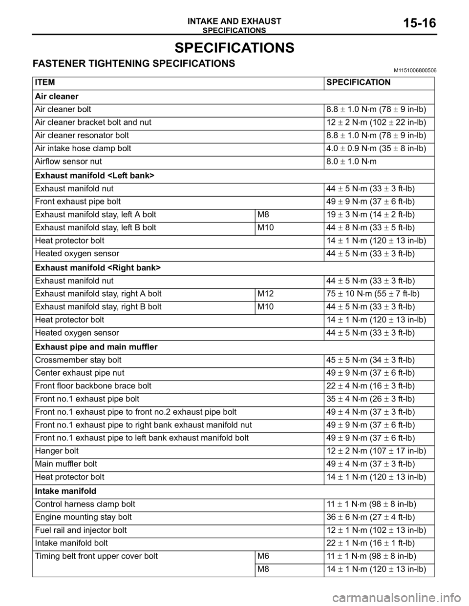
FASTENER TIGHTENING SPECIFICATIONSM1151006800506
ITEMSPECIFICATION
Air cleaner
Air cleaner bolt 8.8
1.0 Nm (78 9 in-lb)
Air cleaner bracket bolt and nut 12
2 Nm (102 22 in-lb)
Air cleaner resonator bolt 8.8
1.0 Nm (78 9 in-lb)
Air intake hose clamp bolt 4.0
0.9 Nm (35 8 in-lb)
Airflow sensor nut 8.0
1.0 Nm
Exhaust manifold
Exhaust manifold nut 44
5 Nm (33 3 ft-lb)
Front exhaust pipe bolt 49
9 Nm (37 6 ft-lb)
Exhaust manifold stay, left A bolt M8 19
3 Nm (14 2 ft-lb)
Exhaust manifold stay, left B bolt M10 44
8 Nm (33 5 ft-lb)
Heat protector bolt 14
1 Nm (120 13 in-lb)
Heated oxygen sensor 44
5 Nm (33 3 ft-lb)
Exhaust manifold
Exhaust manifold nut 44
5 Nm (33 3 ft-lb)
Exhaust manifold stay, right A bolt M12 75
10 Nm (55 7 ft-lb)
Exhaust manifold stay, right B bolt M10 44
5 Nm (33 3 ft-lb)
Heat protector bolt 14
1 Nm (120 13 in-lb)
Heated oxygen sensor 44
5 Nm (33 3 ft-lb)
Exhaust pipe and main muffler
Crossmember stay bolt 45
5 Nm (34 3 ft-lb)
Center exhaust pipe nut 49
9 Nm (37 6 ft-lb)
Front floor backbone brace bolt 22
4 Nm (16 3 ft-lb)
Front no.1 exhaust pipe bolt 35
4 Nm (26 3 ft-lb)
Front no.1 exhaust pipe to front no.2 exhaust pipe bolt 49
4 Nm (37 3 ft-lb)
Front no.1 exhaust pipe to right bank exhaust manifold nut 49
9 Nm (37 6 ft-lb)
Front no.1 exhaust pipe to left bank exhaust manifold bolt 49
9 Nm (37 6 ft-lb)
Hanger bolt 12
2 Nm (107 17 in-lb)
Main muffler bolt 49
4 Nm (37 3 ft-lb)
Heat protector bolt 14
1 Nm (120 13 in-lb)
Intake manifold
Control harness clamp bolt 11
1 Nm (98 8 in-lb)
Engine mounting stay bolt 36
6 Nm (27 4 ft-lb)
Fuel rail and injector bolt 12
1 Nm (102 13 in-lb)
Intake manifold bolt 22
1 Nm (16 1 ft-lb)
Timing belt front upper cover bolt M6 11
1 Nm (98 8 in-lb)
M8 14
1 Nm (120 13 in-lb)
Page 976 of 1500
SPECIFICATIONS
INTAKE AND EXHAUST15-17
Water pump bracket bolt 24 3 Nm (18 2 ft-lb) ITEMSPECIFICATION
Page 977 of 1500
SPECIFICATIONS
INTAKE AND EXHAUST15-18
SERVICE SPECIFICATIONM1151000300462
SEALANTSM1151000500187
Intake manifold plenum
Evaporative emission purge solenoid bolt 9.0
1.0 Nm (80 9 in-lb)
Harness bracket bolt 11
1 Nm (98 8 in-lb)
Intake manifold plenum bolt 18
2 Nm (13 2 ft-lb)
Intake manifold plenum stay bolt M8 18
2 Nm (13 2 ft-lb)
M10 36
6 Nm (27 4 ft-lb)
Manifold absolute pressure sensor bolt 5.0
1.0 Nm (44 9 in-lb)
Power steering pressure hose clamp nut 12
2 Nm (102 22 in-lb)
Power steering pressure hose clamp bracket bolt 12
2 Nm (102 22 in-lb)
Power steering oil pump bracket connecting bolt 41
8 Nm (30 6 ft-lb) ITEMSPECIFICATION
ITEM STANDARD VALUE LIMIT
Manifold distortion of the installation surface mm (in) 0.15 (0.006) or less 0.20 (0.008)
ITEM SPECIFIED SEALANT
Thermostat case assembly 3M
AAD Part No.8672, 3M AAD Part No.8679/8678 or
equivalent
Thermostat case assembly bolt 3M
AAD Part No. 8730, 8731 or equivalent
Page 1024 of 1500
ENGINE ROLL STOPPER AND CENTREMEMBER
POWER PLANT MOUNT32-7
ENGINE ROLL STOPPER AND CENTREMEMBER
REMOVAL AND INSTALLATIONM1321002300306
*: Indicates parts which should be initially tightened, and then fully tightened after placing the vehicle
horizontally and loading the full weight of the engine on the vehicle body.
Pre-removal and Post-installation Operation
Side Under Cover Removal and Installation (Refer to
GROUP 51, Under Cover P.51-13).
FRONT ROLL STOPPER AND
CENTREMEMBER REMOVAL
STEPS
1. SELF-LOCKING NUT
2. ENGINE FRONT ROLL STOPPER
BRACKET AND
CENTREMEMBER
>>B<<3. ENGINE FRONT ROLL STOPPER
BRACKET
4.
CENTREMEMBERREAR ROLL STOPPER
REMOVAL STEPS
FRONT AXLE NO.1
CROSSMEMBER ASSEMBLY
(REFER TO P.32-9).
5. ENGINE REAR ROLL STOPPER
BRACKET
REAR ROLL STOPPER
BRACKET REMOVAL STEPS
FRONT NO.1 EXHAUST PIPE
(REFER TO GROUP 15,
EXHAUST PIPE AND MAIN
MUFFLER P.15-14).
1. SELF-LOCKING NUT
Page 1071 of 1500

HOOD
BODY42-4
HOOD
BODY DIAGNOSIS
INTRODUCTION TO HOOD DIAGNOSISM1421005800363
Wind noise at the hood may be caused by improper
hood adjustment.
HOOD DIAGNOSTIC TROUBLESHOOTING STRATEGYM1421005900337
Use these steps to plan your diagnostic strategy. If
you follow them carefully, you will be sure that you
have exhausted most of the possible ways to find a
hood fault.
1. Gather information from the customer.2. Verify that the condition described by the
customer exists.
3. Find the malfunction by following the Symptom
Chart.
4. Verify malfunction is eliminated.
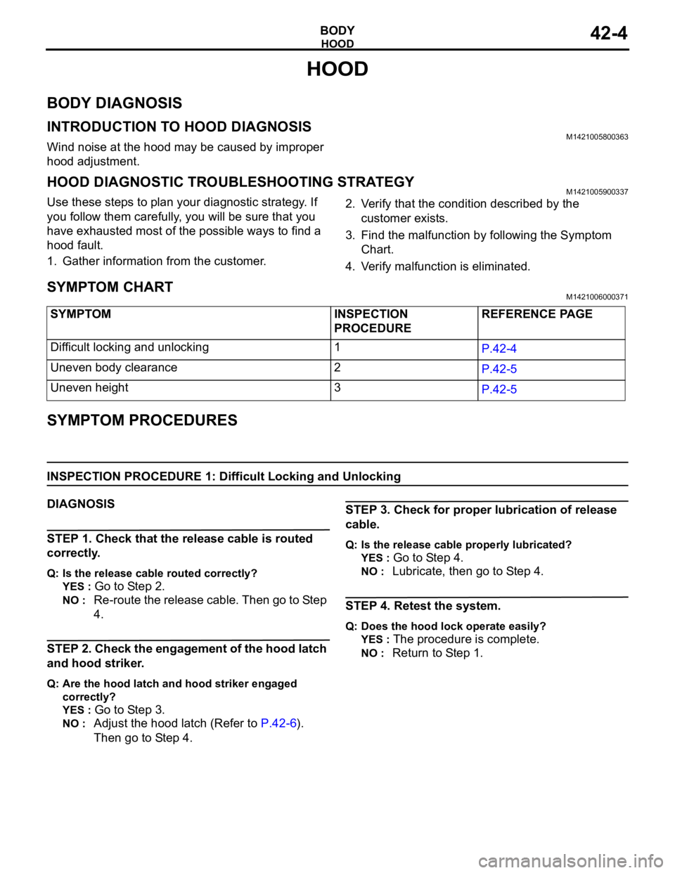
SYMPTOM CHARTM1421006000371
SYMPTOM PROCEDURES
INSPECTION PROCEDURE 1: Difficult Locking and Unlocking
DIAGNOSIS
STEP 1. Check that the release cable is routed
correctly.
Q: Is the release cable routed correctly?
YES :
Go to Step 2.
NO : Re-route the release cable. Then go to Step
4.
STEP 2. Check the engagement of the hood latch
and hood striker.
Q: Are the hood latch and hood striker engaged
correctly?
YES :
Go to Step 3.
NO : Adjust the hood latch (Refer to P.42-6).
Then go to Step 4.
STEP 3. Check for proper lubrication of release
cable.
Q: Is the release cable properly lubricated?
YES :
Go to Step 4.
NO : Lubricate, then go to Step 4.
STEP 4. Retest the system.
Q: Does the hood lock operate easily?
YES :
The procedure is complete.
NO : Return to Step 1. SYMPTOM INSPECTION
PROCEDUREREFERENCE PAGE
Difficult locking and unlocking 1
P.42-4
Uneven body clearance 2
P.42-5
Uneven height 3
P.42-5
Page 1081 of 1500

WINDOW GLASS
BODY42-14
WINDOW GLASS DIAGNOSIS
INTRODUCTION TO WINDOW GLASS DIAGNOSISM1422006700254
If water emerges from the following points, there is a
problem in the seal or body flange.Windshield
Rear window glass
WINDOW GLASS DIAGNOSTIC TROUBLESHOOTING STRATEGYM1422006800240
Use these steps to plan your diagnostic strategy. If
you follow them carefully, you will be sure that you
have exhausted most of the possible ways to find a
window glass fault.
1. Gather information from the customer.2. Verify that the condition described by the
customer exists.
3. Find the malfunction by following the Symptom
Chart.
4. Verify malfunction is eliminated.
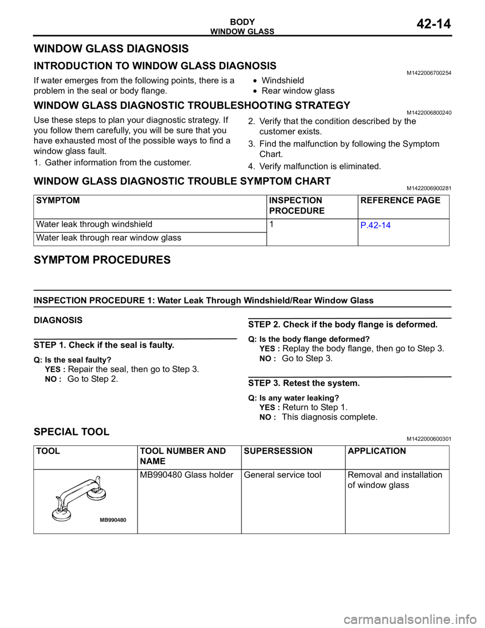
WINDOW GLASS DIAGNOSTIC TROUBLE SYMPTOM CHARTM1422006900281
SYMPTOM PROCEDURES
INSPECTION PROCEDURE 1: Water Leak Through Windshield/Rear Window Glass
DIAGNOSIS
STEP 1. Check if the seal is faulty.
Q: Is the seal faulty?
YES :
Repair the seal, then go to Step 3.
NO : Go to Step 2.
STEP 2. Check if the body flange is deformed.
Q: Is the body flange deformed?
YES :
Replay the body flange, then go to Step 3.
NO : Go to Step 3.
STEP 3. Retest the system.
Q: Is any water leaking?
YES :
Return to Step 1.
NO : This diagnosis complete.
SPECIAL TOOLM1422000600301
SYMPTOM INSPECTION
PROCEDUREREFERENCE PAGE
Water leak through windshield 1
P.42-14
Water leak through rear window glass
TOOL TOOL NUMBER AND
NAMESUPERSESSION APPLICATION
MB990480 Glass holder General service tool Removal and installation
of window glass