Page 1081 of 1500

WINDOW GLASS
BODY42-14
WINDOW GLASS DIAGNOSIS
INTRODUCTION TO WINDOW GLASS DIAGNOSISM1422006700254
If water emerges from the following points, there is a
problem in the seal or body flange.Windshield
Rear window glass
WINDOW GLASS DIAGNOSTIC TROUBLESHOOTING STRATEGYM1422006800240
Use these steps to plan your diagnostic strategy. If
you follow them carefully, you will be sure that you
have exhausted most of the possible ways to find a
window glass fault.
1. Gather information from the customer.2. Verify that the condition described by the
customer exists.
3. Find the malfunction by following the Symptom
Chart.
4. Verify malfunction is eliminated.
WINDOW GLASS DIAGNOSTIC TROUBLE SYMPTOM CHARTM1422006900281
SYMPTOM PROCEDURES
INSPECTION PROCEDURE 1: Water Leak Through Windshield/Rear Window Glass
DIAGNOSIS
STEP 1. Check if the seal is faulty.
Q: Is the seal faulty?
YES :
Repair the seal, then go to Step 3.
NO : Go to Step 2.
STEP 2. Check if the body flange is deformed.
Q: Is the body flange deformed?
YES :
Replay the body flange, then go to Step 3.
NO : Go to Step 3.
STEP 3. Retest the system.
Q: Is any water leaking?
YES :
Return to Step 1.
NO : This diagnosis complete.
SPECIAL TOOLM1422000600301
SYMPTOM INSPECTION
PROCEDUREREFERENCE PAGE
Water leak through windshield 1
P.42-14
Water leak through rear window glass
TOOL TOOL NUMBER AND
NAMESUPERSESSION APPLICATION
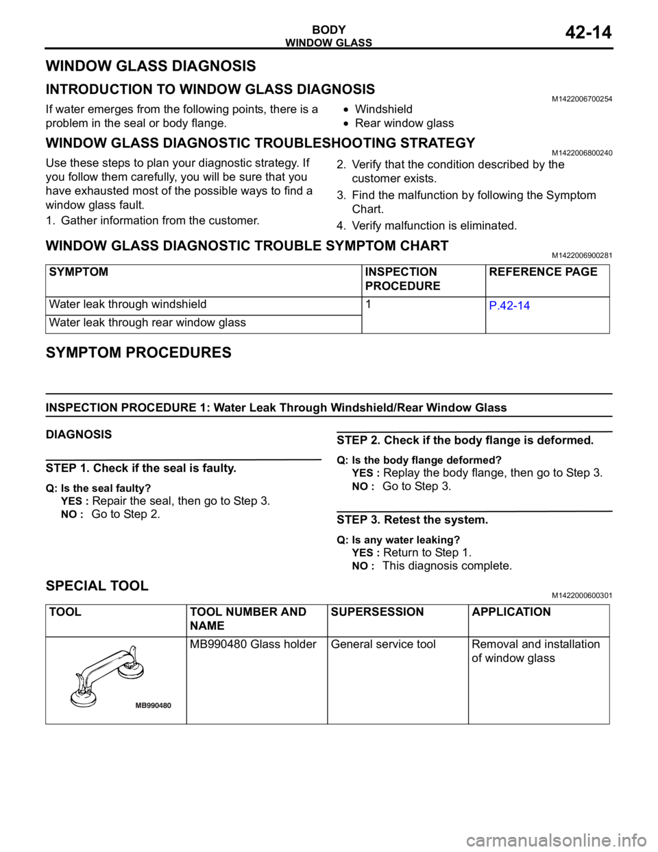
MB990480 Glass holder General service tool Removal and installation
of window glass
Page 1083 of 1500
Page 1085 of 1500
WINDOW GLASS
BODY42-18
INSTALLATION SERVICE POINTS
.
>>A<< WINDSHIELD SPACER/GLASS STOP-
PER/WINDSHIELD UPPER MOLDING/WIND-
SHIELD SIDE MOLDING INSTALLATION
Leave the degreased parts for 3 or more minutes to dry
well, before starting on the next step. Do not touch the
degreased parts.
1. Use 3M
AAD Part number 8906 or equivalent to degrease
the inside and outside of the windshield and the body
flanges.
2. Install the windshield spacer and glass stoppers to the
specified positions so that there are no adrift or warped
surfaces inside the windshield.
3. Install the windshield upper and side moldings to the
windshield.
.
Page 1088 of 1500
Page 1095 of 1500
DOOR
BODY42-28
6. Cut the remaining piece of tape into smaller pieces, attach it
again as it was before, and then remove the pieces one by
one to narrow down the source.
7. Check that wind noise occurs when the last remaining tape
is removed, and that noise does not occur when it is
re-attached.
8. When the source(s) of the wind noise is finally located,
attach butyl tape, body sealer or similar material to obstruct
this source as much as possible.
SPECIAL TOOLSM1423000600348
TOOL TOOL NUMBER AND
NAMESUPERSESSION APPLICATION
MB990900 or
MB991164 Door
adjusting wrenchMB990900-01 Adjustment of door fit
MB990925 Bearing and
oil seal installer set
A: MB990939 Remover
barMB990925-01 or
General service toolAdjustment of door striker
MB990211 Slider
hammerMB990211-01
MB990241 Axle shaft
puller
A: MB990243 Body
pullerMB990241-01 or
General service tool
Page 1096 of 1500
DOOR
BODY42-29
MB990480 Glass holder General service tool Removal of power window
regulator assembly
MB991223 Harness set
A: MB991219 Test
harness
B: MB991220 LED
harness
C: MB991221 LED
harness adapter
D: MB991222 ProbeGeneral service tools Measurement of terminal
voltage
A: Connector pin contact
pressure inspection
B: Power circuit inspection
C: Power circuit inspection
D: Commercial tester
connection
MB990784 Ornament
removerGeneral service tool Removal of power window
switch panel assembly TOOL TOOL NUMBER AND
NAMESUPERSESSION APPLICATION
Page 1097 of 1500

DOOR
BODY42-30
ON-VEHICLE SERVICE
DOOR FIT ADJUSTMENTM1423001100380
Required Special Tools:
MB990211: Slide Hammer
MB990243: Body Puller
MB990900 or MB991164: Door adjusting Wrench
MB990939: Brass Bar
Attach protection tape to the fender and door edges
where the hinge is installed.
Do not rotate special tool MB991164 with a torque of
over 98 N
m (72 ft-lb).
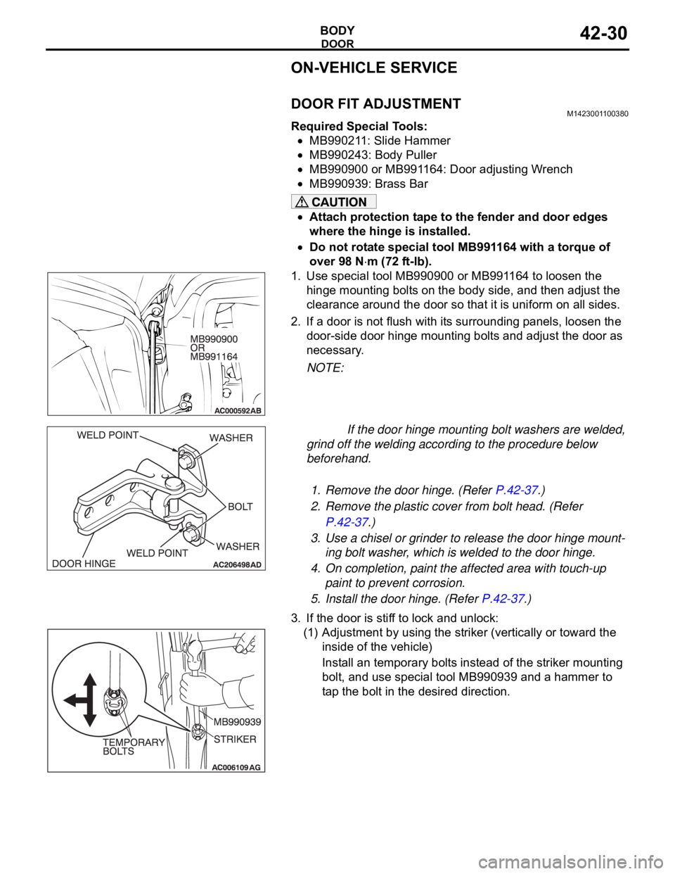
1. Use special tool MB990900 or MB991164 to loosen the
hinge mounting bolts on the body side, and then adjust the
clearance around the door so that it is uniform on all sides.
2. If a door is not flush with its surrounding panels, loosen the
door-side door hinge mounting bolts and adjust the door as
necessary.
NOTE:
If the door hinge mounting bolt washers are welded,
grind off the welding according to the procedure below
beforehand.
.
1. Remove the door hinge. (Refer P.42-37.)
2. Remove the plastic cover from bolt head. (Refer
P.42-37.)
3. Use a chisel or grinder to release the door hinge mount-
ing bolt washer, which is welded to the door hinge.
4. On completion, paint the affected area with touch-up
paint to prevent corrosion.
5. Install the door hinge. (Refer P.42-37.)
3. If the door is stiff to lock and unlock:
(1) Adjustment by using the striker (vertically or toward the
inside of the vehicle)
Install an temporary bolts instead of the striker mounting
bolt, and use special tool MB990939 and a hammer to
tap the bolt in the desired direction.
Page 1105 of 1500
DOOR
BODY42-38
INSTALLATION SERVICE POINTS
.
>>A<< STRIKER INSTALLATION
Align the center of the striker and latch within 1.5 mm (0.06
inch), and install.
.
>>B<< REAR DOOR PROTECTOR FILM
INSTALLATION
Install the rear door protector film as shown.
INSPECTIONM1423006000333
DOOR SWITCH CHECK
Check continuity between the switch terminals and body
ground.
SWITCH
POSITIONTESTER
CONNECTIONSPECIFIED
CONDITION
Released (ON) 1
body ground Less than 2 ohms
Depressed (OFF) 1
body ground Open circuit