Page 1014 of 1500
IGNITION SYSTEM
ENGINE ELECTRICAL16-37
INSTALLATION SERVICE POINT
.
>>A<< KNOCK SENSOR INSTALLATION
Use special tool MD998773 to install the knock sensor.
Page 1016 of 1500
SPECIFICATIONS
ENGINE ELECTRICAL16-39
SERVICE SPECIFICATIONSM1161000300322
ITEMS STANDARD VALUE LIMIT
Alternator
Regulated voltage
(Ambient temperature at voltage
regulator)
20C (4F)14.2 15.4
20C (68F) 13.9 14.9
60C (140F) 13.4 14.5
80C (176F) 13.1 14.5
Alternator output wire voltage drop (at 30 A) VMaximum 0.3
Nominal Output current 110A 70 % of normal output
current
Field coil resistance
Approximately 2 5
Brush protrusion length mm (in)Minimum 2 (0.08)
Starter motor
Free running characteristics Terminal voltage
V11
Current A 95
Speed r/min 2,500 or more
Pinion gap mm (in) 0.5 2.0 (0.02 0.07)
Commutator run-out mm (in) 0.05 (0.002) Minimum 0.1 (0.004)
Commutator diameter mm (in) 29.4 (1.16) Minimum 28.8 (1.13)
Undercut depth mm (in) 0.5 (0.02) Minimum 0.2 (0.008)
Ignition parts
Spark plug gap mm 1.0 1.1
Page 1020 of 1500
SPECIAL TOOL
POWER PLANT MOUNT32-3
SPECIAL TOOLM1321000600390
TOOL TOOL NUMBER
AND NAMESUPERSESSION APPLICATION
MB991897
Ball joint removerMB991113-01,
MB990635-01 or
General service tool Knuckle and tie rod end ball joint
disconnection
NOTE: Steering linkage puller
(MB990635 or MB991113)is also
used to disconnect the knuckle
and tie rod end ball joint.
Page 1023 of 1500
TRANSAXLE MOUNTING
POWER PLANT MOUNT32-6
INSTALLATION SERVICE POINT
.
>>A<< TRANSAXLE MOUNTING STOPPER
INSTALLATION
Install the transaxle mounting stopper so that its arrow points
upward.
Page 1025 of 1500
ENGINE ROLL STOPPER AND CENTREMEMBER
POWER PLANT MOUNT32-8
INSTALLATION SERVICE POINTS
.
>>B<< ENGINE FRONT ROLL STOPPER
BRACKET INSTALLATION
Install the engine front roll stopper bracket so that its hole
points towards the front side of the vehicle.
2. ENGINE FRONT ROLL STOPPER
BRACKET AND
CENTREMEMBER
6. SELF-LOCKING NUT
7. TRANSAXLE CASE REAR ROLL
STOPPER BRACKET REAR ROLL STOPPER
BRACKET REMOVAL STEPS
Page 1026 of 1500

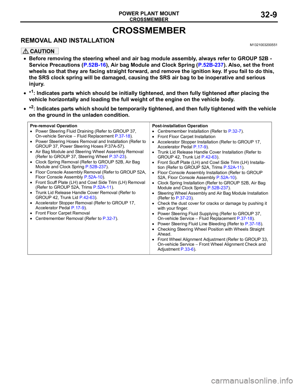
CROSSMEMBER
POWER PLANT MOUNT32-9
CROSSMEMBER
REMOVAL AND INSTALLATIONM1321003200551
Before removing the steering wheel and air bag module assembly, always refer to GROUP 52B -
Service Precautions (P.52B-16), Air bag Module and Clock Spring (P.52B-237). Also, set the front
wheels so that they are facing straight forward, and remove the ignition key. If you fail to do this,
the SRS clock spring will be damaged, causing the SRS air bag to be inoperative and serious
injury.
*1: Indicates parts which should be initially tightened, and then fully tightened after placing the
vehicle horizontally and loading the full weight of the engine on the vehicle body.
*2: Indicates parts which should be temporarily tightened, and then fully tightened with the vehicle
on the ground in the unladen condition.
Pre-removal Operation
Power Steering Fluid Draining (Refer to GROUP 37,
On-vehicle Service Fluid Replacement P.37-18).
Power Steering Hoses Removal and Installation (Refer to
GROUP 37, Power Steering Hoses P.37A-57).
Air Bag Module and Steering Wheel Assembly Removal
(Refer to GROUP 37, Steering Wheel P.37-23).
Clock Spring Removal (Refer to GROUP 52B, Air Bag
Module and Clock Spring P.52B-237).
Floor Console Assembly Removal (Refer to GROUP 52A,
Floor Console Assembly P.52A-10).
Front Scuff Plate (LH) and Cowl Side Trim (LH) Removal
(Refer to GROUP 52A, Trims P.52A-11).
Trunk Lid Release Handle Cover Removal (Refer to
GROUP 42, Trunk Lid P.42-63).
Accelerator Stopper Removal (Refer to GROUP 17,
Accelerator Pedal P.17-9).
Front Floor Carpet Removal
Centremember Removal (Refer to P.32-7).Post-installation Operation
Centremember Installation (Refer to P.32-7).
Front Floor Carpet Installation
Accelerator Stopper Installation (Refer to GROUP 17,
Accelerator Pedal P.17-9).
Trunk Lid Release Handle Cover Installation (Refer to
GROUP 42, Trunk Lid P.42-63).
Front Scuff Plate (LH) and Cowl Side Trim (LH) Installa-
tion (Refer to GROUP 52A, Trims P.52A-11).
Floor Console Assembly Installation (Refer to GROUP
52A, Floor Console Assembly P.52A-10).
Clock Spring Installation (Refer to GROUP 52B, Air Bag
Module and Clock Spring P.52B-237).
Steering Wheel Assembly and Air Bag Module Installation
(Refer to P.37-23).
Check the dust cover for cracks or damage by pushing it
with your finger.
Power Steering Fluid Supplying (Refer to GROUP 37,
On-vehicle Service Fluid Replacement P.37-18).
Power Steering Fluid Line Bleeding (Refer to P.37-18).
Checking Steering Wheel Position with Wheels Straight
Ahead.
Front Wheel Alignment Adjustment (Refer to GROUP 33,
On-vehicle Service
Front Wheel Alignment Check and
Adjustment P.33-6).
Page 1028 of 1500
Page 1030 of 1500
CROSSMEMBER
POWER PLANT MOUNT32-13
<> FRONT AXLE CROSSMEMBER
MOUNTING BOLT REMOVAL
Remove the crossmember mounting bolt.
.
<> ENGINE REAR ROLL STOPPER BRACKET,
POWER STEERING GEAR AND LINKAGE,
STABILIZER BAR AND FRONT AXLE NO.1
CROSSMEMBER ASSEMBLY REMOVAL
Support the front axle number 1 crossmember with a transmis-
sion jack, and then remove the crossmember mounting nuts
and bolts.
INSTALLATION SERVICE POINTS
.
>>A<< STABILIZER BAR INSTALLATION
Align the stabilizer bar identification mark with the right end of
the bushing (LH).
.