Page 870 of 1500
CONDENSER AND CONDENSER FAN
HEATER, AIR CONDITIONING AND VENTILATION55-169
>>B<< CONDENSER INSTALLATION
When replacing the condenser, refill it with a specified amount
of compressor oil and install it to the vehicle.
Compressor oil: ND Oil 8
Quantity: 40 ml
INSPECTIONM1552014301102
CONDENSER FAN MOTOR CHECK
Check to be sure that the condenser fan motor operates when
battery voltage is applied to terminal 2 and terminal 1
grounded.
Page 907 of 1500

HOW TO DIAGNOSE
GENERAL 00E-6
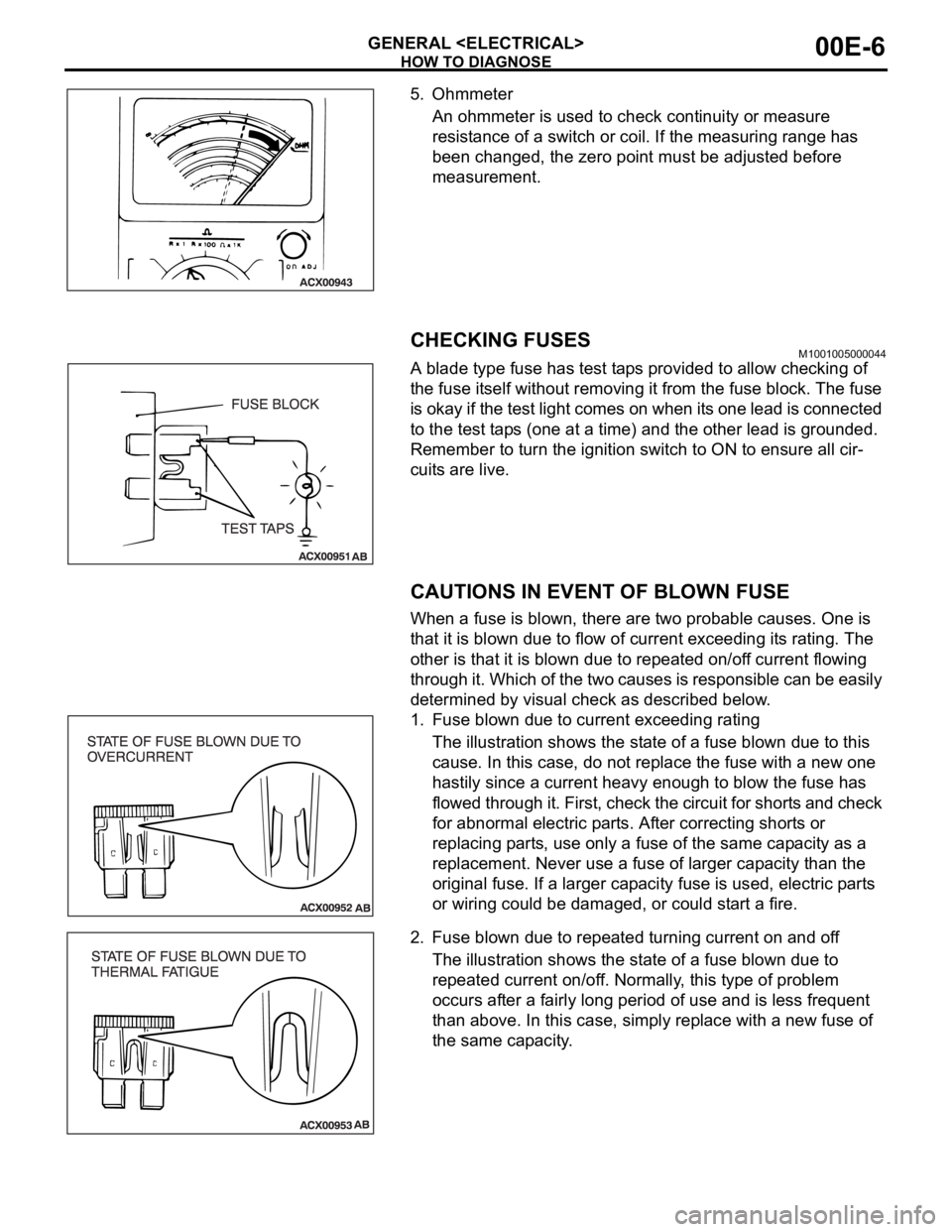
5. Ohmmeter
An ohmmeter is used to check continuity or measure
resistance of a switch or coil. If the measuring range has
been changed, the zero point must be adjusted before
measurement.
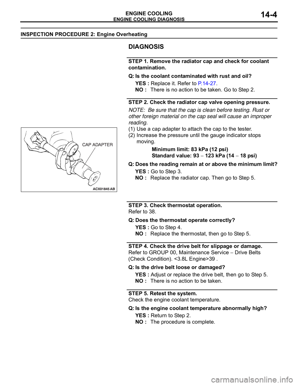
CHECKING FUSESM1001005000044
A blade type fuse has test taps provided to allow checking of
the fuse itself without removing it from the fuse block. The fuse
is okay if the test light comes on when its one lead is connected
to the test taps (one at a time) and the other lead is grounded.
Remember to turn the ignition switch to ON to ensure all cir-
cuits are live.
CAUTIONS IN EVENT OF BLOWN FUSE
When a fuse is blown, there are two probable causes. One is
that it is blown due to flow of current exceeding its rating. The
other is that it is blown due to repeated on/off current flowing
through it. Which of the two causes is responsible can be easily
determined by visual check as described below.
1. Fuse blown due to current exceeding rating
The illustration shows the state of a fuse blown due to this
cause. In this case, do not replace the fuse with a new one
hastily since a current heavy enough to blow the fuse has
flowed through it. First, check the circuit for shorts and check
for abnormal electric parts. After correcting shorts or
replacing parts, use only a fuse of the same capacity as a
replacement. Never use a fuse of larger capacity than the
original fuse. If a larger capacity fuse is used, electric parts
or wiring could be damaged, or could start a fire.
2. Fuse blown due to repeated turning current on and off
The illustration shows the state of a fuse blown due to
repeated current on/off. Normally, this type of problem
occurs after a fairly long period of use and is less frequent
than above. In this case, simply replace with a new fuse of
the same capacity.
Page 909 of 1500

HOW TO DIAGNOSE
GENERAL 00E-8
CHECKING RELAYSM1001004900152
1. By using a relay, a heavy current can be turned on and off by
a switch using much less current. For example, in the circuit
shown here, when the switch is turned on (closed), current
flows to the coil of the relay. Then, its contact is turned on
(closed) and the light comes on. The current flowing through
the switch is much less than that for the light.
2. When current flows through the coil of a relay, its core is
magnetized to attract the iron piece, closing (ON) the
contact at the tip of the iron piece. When the coil current is
turned off, the iron piece returns to its original position by a
spring, opening the contact (OFF).
3. Relays may be classified as the normally open-type or the
normally closed-type, depending on their contact
construction.
NOTE: The deenergised state means that no current is flow-
ing through the coil. The energised state means that current
is flowing through the coil.
(1) The normally open-type
When a normally open relay as illustrated here is
checked, there should be no continuity between terminals
3 and 4 when the relay is deenergised. There should be
continuity between terminals 3 and 4 when battery
voltage and ground are applied to terminals 1 and 2. The
relay condition is determined by this check.
NOTE: Check the relay in both situation which is
energised and is not energised.
(2) The normally closed-type
When a normally closed relay as illustrated here is
checked, there should be continuity between terminals 3
and 4 when the relay is deenergised. There should be no
continuity between terminals 3 and 4 when battery
voltage and ground are applied to terminals 1 and 2. The
relay condition is determined by this check.
NOTE: Check the relay in both situation which is
energised and is not energised.
Page 919 of 1500

ENGINE COOLING DIAGNOSIS
ENGINE COOLING14-4
INSPECTION PROCEDURE 2: Engine Overheating
DIAGNOSIS
STEP 1. Remove the radiator cap and check for coolant
contamination.
Q: Is the coolant contaminated with rust and oil?
YES : Replace it. Refer to P.14-27.
NO : There is no action to be taken. Go to Step 2.
STEP 2. Check the radiator cap valve opening pressure.
NOTE: Be sure that the cap is clean before testing. Rust or
other foreign material on the cap seal will cause an improper
reading.
(1) Use a cap adapter to attach the cap to the tester.
(2) Increase the pressure until the gauge indicator stops
moving.
Minimum limit: 83 kPa (12 psi)
Standard value: 93
123 kPa (14 18 psi)
Q: Does the reading remain at or above the minimum limit?
YES : Go to Step 3.
NO : Replace the radiator cap. Then go to Step 5.
STEP 3. Check thermostat operation.
Refer to 38.
Q: Does the thermostat operate correctly?
YES : Go to Step 4.
NO : Replace the thermostat, then go to Step 5.
STEP 4. Check the drive belt for slippage or damage.
Refer to GROUP 00, Maintenance Service
Drive Belts
(Check Condition). <3.8L Engine>39 .
Q: Is the drive belt loose or damaged?
YES : Adjust or replace the drive belt, then go to Step 5.
NO : There is no action to be taken.
STEP 5. Retest the system.
Check the engine coolant temperature.
Q: Is the engine coolant temperature abnormally high?
YES : Return to Step 2.
NO : The procedure is complete.
Page 947 of 1500
Page 956 of 1500
WATER HOSE AND WATER PIPE
ENGINE COOLING14-41
INSTALLATION SERVICE POINTS
.
>>A<< O-RING INSTALLATION
Do not allow engine oil or other grease to adhere to the
O-ring
Insert the O-ring to the water pipe, and coat the outer portion of
the O-ring with water or engine coolant.
.
>>B<< ENGINE COOLANT TEMPERATURE
SENSOR INSTALLATION
Apply the specified sealant to the thread of the engine coolant
temperature sensor, and then tighten it to the specified torque.
Specified Sealant: 3M
AAD Part No. 8731 or equiva-
lent
.
>>C<< RADIATOR UPPER HOSE CONNECTION
1. Insert each hose as far as the projection of the water outlet
fitting.
2. Align the mating marks on the radiator hose and hose
clamp, and then connect the radiator hose.
INSPECTIONM1141003400337.
Water Pipe and Hose Check
Check the water pipe and hose for cracks, damage and clogs.
Replace them if necessary.
Page 968 of 1500

INTAKE MANIFOLD
INTAKE AND EXHAUST15-9
>>C<< FUEL HIGH-PRESSURE HOSE
INSTALLATION
Be careful not to allow any engine oil to enter the fuel
rail.
Be careful not to bend the fuel high-pressure hose as it
is made of plastics.
1. When connecting the fuel high-pressure hose to the fuel rail,
apply a small amount of new engine oil to the O-ring and
then insert the fuel high-pressure hose, being careful not to
damage the O-ring.
2. While turning the fuel high-pressure hose to the left and
right, install it to the fuel rail.
3. Check that the injector turns smoothly. If it does not turn
smoothly, the O-ring may be trapped. Remove the fuel
high-pressure hose and then re-insert it into the fuel rail and
check again.
INSPECTIONM1151003100672
Check the following points; replace the part if a problem is
found.
.
Intake Manifold Check
1. Check for damage or cracking of any part.
2. Clogging of the negative pressure (vacuum) outlet port.
3. Using a straight edge and feeler gauge, check for distortion
of the cylinder head installation surface.
Standard value: 0.15 mm (0.006 inch) or less
Limit: 0.20 mm (0.008 inch)
Page 978 of 1500

16-1
GROUP 16
ENGINE
ELECTRICAL
CONTENTS
CHARGING SYSTEM . . . . . . . .
16-2
GENERAL DESCRIPTION . . . . . .
16-2
CHARGING SYSTEM DIAGNOSIS16-3
SPECIAL TOOL . . . . . . . . . . . . . . .16-6
ON-VEHICLE SERVICE. . . . . . . . .16-7
ALTERNATOR OUTPUT WIRE VOLTAGE
DROP TEST . . . . . . . . . . . . . . . . . . . . . 16-7
OUTPUT CURRENT TEST . . . . . . . . . . 16-8
REGULATED VOLTAGE TEST . . . . . . . 16-10
WAVE PATTERN CHECK USING AN
OSCILLOSCOPE . . . . . . . . . . . . . . . . . . 16-11
ALTERNATOR ASSEMBLY . . . . .16-14
REMOVAL AND INSTALLATION . . . . . 16-14
DISASSEMBLY AND ASSEMBLY. . . . . 16-15
INSPECTION . . . . . . . . . . . . . . . . . . . . . 16-17
STARTING SYSTEM . . . . . . . . .16-20
GENERAL DESCRIPTION . . . . . .
16-20
STARTING SYSTEM DIAGNOSIS . . . . 16-21
STARTER MOTOR ASSEMBLY . .16-23
REMOVAL AND INSTALLATION . . . . . 16-23
INSPECTION . . . . . . . . . . . . . . . . . . . . . 16-24
DISASSEMBLY AND ASSEMBLY. . . . . 16-26
INSPECTION . . . . . . . . . . . . . . . . . . . . . 16-28
IGNITION SYSTEM . . . . . . . . . . . . . .16-30GENERAL DESCRIPTION . . . . . . .
16-30
SPECIAL TOOLS . . . . . . . . . . . . . .16-30
ON-VEHICLE SERVICE . . . . . . . . .16-31
KNOCK CONTROL SYSTEM CHECK . . 16-31
IGNITION COIL CHECK. . . . . . . . . . . . . 16-31
SPARK PLUG TEST . . . . . . . . . . . . . . . 16-32
SPARK PLUG CHECK AND CLEANING16-32
CAMSHAFT POSITION SENSOR CHECK16-32
CRANKSHAFT POSITION SENSOR
CHECK . . . . . . . . . . . . . . . . . . . . . . . . . . 16-32
IGNITION COIL . . . . . . . . . . . . . . . .16-33
REMOVAL AND INSTALLATION . . . . . 16-33
CAMSHAFT POSITION SENSOR .16-34
REMOVAL AND INSTALLATION . . . . . 16-34
CRANKSHAFT POSITION SENSOR16-35
REMOVAL AND INSTALLATION . . . . . 16-35
KNOCK SENSOR . . . . . . . . . . . . . .16-36
REMOVAL AND INSTALLATION . . . . . 16-36
SPECIFICATIONS . . . . . . . . . . 16-38
FASTENER TIGHTENING
SPECIFICATIONS . . . . . . . . . . . . .
16-38
GENERAL SPECIFICATIONS . . . .16-38
SERVICE SPECIFICATIONS . . . . .16-39