2005 MITSUBISHI 380 check oil
[x] Cancel search: check oilPage 1009 of 1500
IGNITION SYSTEM
ENGINE ELECTRICAL16-32
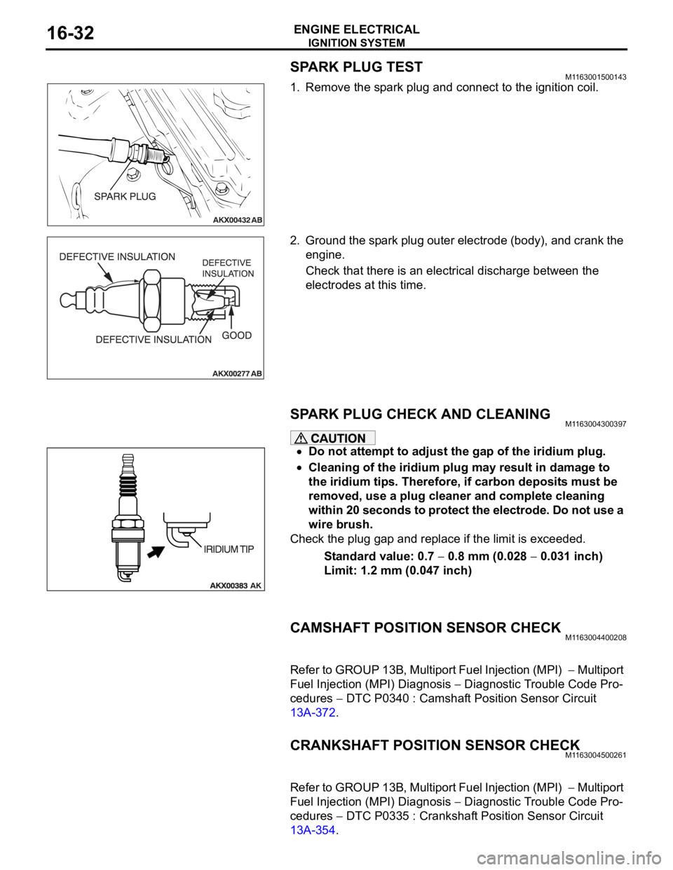
SPARK PLUG TESTM1163001500143
1. Remove the spark plug and connect to the ignition coil.
2. Ground the spark plug outer electrode (body), and crank the
engine.
Check that there is an electrical discharge between the
electrodes at this time.
SPARK PLUG CHECK AND CLEANING M1163004300397
Do not attempt to adjust the gap of the iridium plug.
Cleaning of the iridium plug may result in damage to
the iridium tips. Therefore, if carbon deposits must be
removed, use a plug cleaner and complete cleaning
within 20 seconds to protect the electrode. Do not use a
wire brush.
Check the plug gap and replace if the limit is exceeded.
Standard value: 0.7
0.8 mm (0.028 0.031 inch)
Limit: 1.2 mm (0.047 inch)
CAMSHAFT POSITION SENSOR CHECKM1163004400208
Refer to GROUP 13B, Multiport Fuel Injection (MPI) Multiport
Fuel Injection (MPI) Diagnosis
Diagnostic Trouble Code Pro-
cedures
DTC P0340 : Camshaft Position Sensor Circuit
13A-372.
CRANKSHAFT POSITION SENSOR CHECKM1163004500261
Refer to GROUP 13B, Multiport Fuel Injection (MPI) Multiport
Fuel Injection (MPI) Diagnosis
Diagnostic Trouble Code Pro-
cedures
DTC P0335 : Crankshaft Position Sensor Circuit
13A-354.
Page 1034 of 1500
51-1
GROUP 51
EXTERIOR
CONTENTS
FRONT BUMPER ASSEMBLY . . . . .51-2
REMOVAL AND INSTALLATION . . . . . . . . 51-2
DISASSEMBLY AND ASSEMBLY . . . . . . . 51-3
REAR BUMPER ASSEMBLY . . . . . .51-5
REMOVAL AND INSTALLATION . . . . . . . . 51-5
RADIATOR GRILLE. . . . . . . . . . . . . .51-6
REMOVAL AND INSTALLATION . . . . . . . . 51-6
GARNISHES AND MOLDINGS . . . . .51-7
SPECIAL TOOLS . . . . . . . . . . . . . . . . . . . . 51-7
MOLDINGS . . . . . . . . . . . . . . . . . . . . . . . . . 51-8
REMOVAL AND INSTALLATION . . . . . . . . 51-8
REAR SPOILER . . . . . . . . . . . . . . . . .51-11
REMOVAL AND INSTALLATION . . . . . . . . 51-11
MUD GUARD . . . . . . . . . . . . . . . . . . .51-12
REMOVAL AND INSTALLATION . . . . . . . . 51-12
UNDER COVER . . . . . . . . . . . . . . . . .51-13
REMOVAL AND INSTALLATION . . . . . . . . 51-13
WINDSHIELD WIPER AND WASHER51-14
GENERAL DESCRIPTION . . . . . . . . . . . . . 51-14
WINDSHIELD WIPER AND WASHER DIAGNOSIS . . . . . . . . . . . . . . . . . . . . . . . . . 51-14
SPECIAL TOOLS . . . . . . . . . . . . . . . . . . . . 51-15
ON-VEHICLE SERVICE . . . . . . . . . . . . . . . 51-15
WINDSHIELD INTERMITTENT WIPER
VOLUME CHECK . . . . . . . . . . . . . . . . . . . . 51-15
WINDSHIELD WASHER FLUID EJECTION
CHECK . . . . . . . . . . . . . . . . . . . . . . . . . . . . 51-16
WINDSHIELD WIPER . . . . . . . . . . . . . . . . . 51-17
REMOVAL AND INSTALLATION . . . . . . . . 51-17
INSPECTION. . . . . . . . . . . . . . . . . . . . . . . . 51-20
WINDSHIELD WASHER . . . . . . . . . . . . . . . 51-23
REMOVAL AND INSTALLATION . . . . . . . . 51-23
INSPECTION. . . . . . . . . . . . . . . . . . . . . . . . 51-24
MARK . . . . . . . . . . . . . . . . . . . . . . . . .51-25
REMOVAL AND INSTALLATION . . . . . . . . 51-25
DOOR MIRROR . . . . . . . . . . . . . . . . .51-27
GENERAL DESCRIPTION . . . . . . . . . . . . . 51-27
DOOR MIRROR . . . . . . . . . . . . . . . . . . . . . 51-28
REMOVAL AND INSTALLATION . . . . . . . . 51-28
INSPECTION. . . . . . . . . . . . . . . . . . . . . . . . 51-29
SPECIFICATIONS . . . . . . . . . . . . . . .51-31
FASTENER TIGHTENING SPECIFICATIONS51-31
SERVICE SPECIFICATIONS . . . . . . . . . . . 51-31
ADHESIVE . . . . . . . . . . . . . . . . . . . . . . . . . 51-31
Page 1095 of 1500
DOOR
BODY42-28
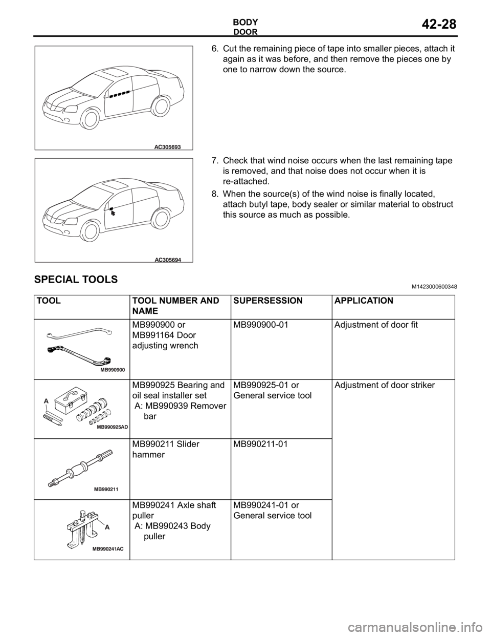
6. Cut the remaining piece of tape into smaller pieces, attach it
again as it was before, and then remove the pieces one by
one to narrow down the source.
7. Check that wind noise occurs when the last remaining tape
is removed, and that noise does not occur when it is
re-attached.
8. When the source(s) of the wind noise is finally located,
attach butyl tape, body sealer or similar material to obstruct
this source as much as possible.
SPECIAL TOOLSM1423000600348
TOOL TOOL NUMBER AND
NAMESUPERSESSION APPLICATION
MB990900 or
MB991164 Door
adjusting wrenchMB990900-01 Adjustment of door fit
MB990925 Bearing and
oil seal installer set
A: MB990939 Remover
barMB990925-01 or
General service toolAdjustment of door striker
MB990211 Slider
hammerMB990211-01
MB990241 Axle shaft
puller
A: MB990243 Body
pullerMB990241-01 or
General service tool
Page 1168 of 1500
BASIC BRAKE SYSTEM DIAGNOSIS
BASIC BRAKE SYSTEM35A-3
BASIC BRAKE SYSTEM DIAGNOSIS
INTRODUCTION TO BASIC BRAKE SYSTEM DIAGNOSISM1351009700319
Hydraulic brakes are composed of the brake pedal,
master cylinder, brake booster and disc brakes. Mal-
functions such as insufficient braking power or the
generation of noise may occur due to wear, damage
or incorrect adjustment of these components.
BASIC BRAKE SYSTEM DIAGNOSTIC TROUBLESHOOTING STRATEGYM1351009800316
Use these steps to plan your diagnostic strategy. If
you follow them carefully, you will be sure that you
have exhausted most of the possible ways to find a
basic brake system fault.
1. Gather information from the customer.2. Verify that the condition described by the
customer exists.
3. Find the malfunction by following the symptom
chart.
4. Verify malfunction is eliminated.
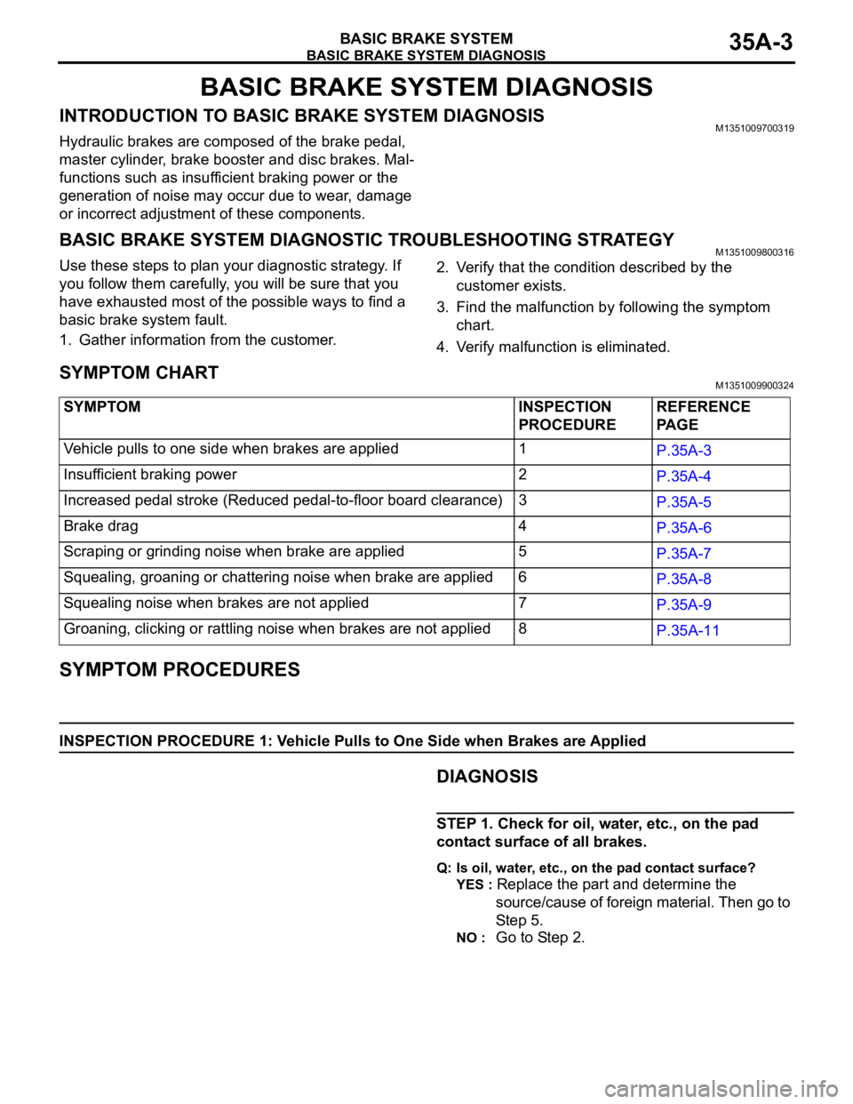
SYMPTOM CHARTM1351009900324
SYMPTOM PROCEDURES
INSPECTION PROCEDURE 1: Vehicle Pulls to One Side when Brakes are Applied
.DIAGNOSIS
STEP 1. Check for oil, water, etc., on the pad
contact surface of all brakes.
Q: Is oil, water, etc., on the pad contact surface?
YES :
Replace the part and determine the
source/cause of foreign material. Then go to
St e p 5.
NO : Go to Step 2. SYMPTOM INSPECTION
PROCEDUREREFERENCE
PA G E
Vehicle pulls to one side when brakes are applied 1
P.35A-3
Insufficient braking power 2
P.35A-4
Increased pedal stroke (Reduced pedal-to-floor board clearance)3
P.35A-5
Brake drag 4
P.35A-6
Scraping or grinding noise when brake are applied 5
P.35A-7
Squealing, groaning or chattering noise when brake are applied 6
P.35A-8
Squealing noise when brakes are not applied 7
P.35A-9
Groaning, clicking or rattling noise when brakes are not applied8
P.35A-11
Page 1170 of 1500
BASIC BRAKE SYSTEM DIAGNOSIS
BASIC BRAKE SYSTEM35A-5
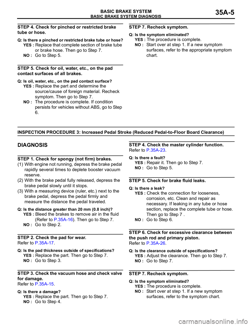
STEP 4. Check for pinched or restricted brake
tube or hose.
Q: Is there a pinched or restricted brake tube or hose?
YES :
Replace that complete section of brake tube
or brake hose. Then go to Step 7.
NO : Go to Step 5.
STEP 5. Check for oil, water, etc., on the pad
contact surfaces of all brakes.
Q: Is oil, water, etc., on the pad contact surface?
YES :
Replace the part and determine the
source/cause of foreign material. Recheck
symptom. Then go to Step 7.
NO : The procedure is complete. If condition
persists for vehicles without ABS, go to Step
6.
STEP 7. Recheck symptom.
Q: Is the symptom eliminated?
YES :
The procedure is complete.
NO : Start over at step 1. If a new symptom
surfaces, refer to the appropriate symptom
chart.
INSPECTION PROCEDURE 3: Increased Pedal Stroke (Reduced Pedal-to-Floor Board Clearance)
.
DIAGNOSIS
STEP 1. Check for spongy (not firm) brakes.
(1) With engine not running, depress the brake pedal
rapidly several times to deplete booster vacuum
reserve.
(2) With the brake pedal fully released, depress the
brake pedal slowly until it stops.
(3) With a measuring device (ruler, etc.) next to the
brake pedal, depress the pedal firmly and
measure the distance the pedal traveled.
Q: Is the distance greater than 20 mm (0.8 inch)?
YES :
Bleed the brakes to remove air in the fluid
(Refer to P.35A-16). Then go to Step 7.
NO : Go to Step 2.
STEP 2. Check the pad for wear.
Refer to P.35A-17.
Q: Is the pad thickness outside of specifications?
YES :
Replace the part. Then go to Step 7.
NO : Go to Step 3.
STEP 3. Check the vacuum hose and check valve
for damage.
Refer to P.35A-15.
Q: Is there a damage?
YES :
Replace the part. Then go to Step 7.
NO : Go to Step 4.
STEP 4. Check the master cylinder function.
Refer to P.35A-23.
Q: Is there a fault?
YES :
Repair it. Then go to Step 7.
NO : Go to Step 5.
STEP 5. Check for brake fluid leaks.
Q: Is there a leak?
YES :
Check the connection for looseness,
corrosion, etc. Clean and repair as
necessary. If leaking in any tube or hose
section, replace the complete tube or hose.
Then go to Step 7 .
NO : Go to Step 6.
STEP 6. Check for excessive clearance between
the push rod and primary piston.
Refer to P.35A-26.
Q: Is the clearance outside of specifications?
YES :
Adjust the clearance. Then go to Step 7.
NO : Go to Step 7.
STEP 7. Recheck symptom.
Q: Is the symptom eliminated?
YES :
The procedure is complete.
NO : Start over at step 1. If a new symptom
surfaces, refer to the symptom chart.
Page 1196 of 1500
DISC BRAKE ASSEMBLY
BASIC BRAKE SYSTEM35A-31
INSTALLATION SERVICE POINT
.
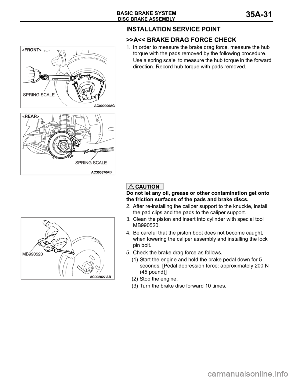
>>A<< BRAKE DRAG FORCE CHECK
1. In order to measure the brake drag force, measure the hub
torque with the pads removed by the following procedure.
Use a spring scale to measure the hub torque in the forward
direction. Record hub torque with pads removed.
Do not let any oil, grease or other contamination get onto
the friction surfaces of the pads and brake discs.
2. After re-installing the caliper support to the knuckle, install
the pad clips and the pads to the caliper support.
3. Clean the piston and insert into cylinder with special tool
MB990520.
4. Be careful that the piston boot does not become caught,
when lowering the caliper assembly and installing the lock
pin bolt.
5. Check the brake drag force as follows.
(1) Start the engine and hold the brake pedal down for 5
seconds. [Pedal depression force: approximately 200 N
(45 pound)]
(2) Stop the engine.
(3) Turn the brake disc forward 10 times.
Page 1210 of 1500
ON-VEHICLE SERVICE
PARKING BRAKES36-3
SYMPTOM PROCEDURES
INSPECTION PROCEDURE 1: Insufficient Parking Brake Function
DIAGNOSIS
STEP 1. Check the excessive parking brake lever
stroke.
Refer to P.36-3.
Q: Is the parking brake lever stroke adjusted
properly?
YES :
Go to Step 2.
NO : Adjust the parking brake lever stroke or
check the parking brake cable routing. Then
go to Step 5.
STEP 2. Check the parking brake cable for
sticking.
Q: Is the parking brake cable stuck?
YES :
Replace the cable. Then go to Step 5.
NO : Go to Step 3.
STEP 3. Check the brake lining and brake drum
for wear.
Refer to P.36-11.
Q: Is the brake lining thickness or brake drum inside
diameter outside of specification?
YES :
Replace the rear brake shoe assembly or
rear brake disc (Refer to P.36-8). Then go to
Step 5.
NO : Go to Step 4.
STEP 4. Check for oil, water, etc., on the lining
contact surfaces.
Q: Is oil, water, etc., on the lining contact surface?
YES :
Replace the part and determine and repair
source/cause of foreign material. Then go to
St e p 5.
NO : Carry out the parking brake lining seating
(Refer to P.36-5) and then go to Step 5.
STEP 5. Retest the system.
Q: Is the malfunction eliminated?
YES :
The procedure is complete.
NO : Recheck from Step 1.
ON-VEHICLE SERVICE
PARKING BRAKE LEVER STROKE CHECK AND
ADJUSTMENT
M1361000900362
1. Pull the parking brake lever with a force of approximately
200 N (45 pounds) and count the number of notches.
Standard value: 5
7 notches
2. If the parking brake lever stroke is not within the standard
value, adjust as described below.
(1) Release the parking brake.
Page 1223 of 1500
GENERAL00-2
MAINTENANCE SERVICE . . . . . . . .00-37
1. FUEL SYSTEM (TANK, PIPE LINE AND
CONNECTION, AND FUEL TANK FILLER
TUBE CAP) (CHECK FOR LEAKS) . . . . . . 00-37
2. FUEL HOSES (CHECK CONDITION) . . 00-37
3. AIR CLEANER FILTER (REPLACE). . . . 00-37
4. EVAPORATIVE EMISSION SYSTEM
(EXCEPT EVAPORATIVE EMISSION
CANISTER) (CHECK FOR CLOGGING) . . 00-37
5. SPARK PLUGS (REPLACE). . . . . . . . . . 00-38
7. TIMING BELT (REPLACE) . . . . . . . . . . . 00-38
8. DRIVE BELTS (FOR ALTERNATOR, POWER
STEERING PUMP AND AIR CONDITIONING)
(CHECK) . . . . . . . . . . . . . . . . . . . . . . . . . . . 00-39
9. EXHAUST SYSTEM (CONNECTIONS
PORTION OF MUFFLER, MUFFLER PIPES
AND CONVERTER HEAT SHIELDS) (CHECK
AND SERVICE AS REQUIRED) . . . . . . . . . 00-44
10. ENGINE OIL (CHANGE) . . . . . . . . . . . . 00-4411. ENGINE OIL FILTER (REPLACE) . . . . 00-44
12. TRANSMISSION FLUID . . . . . . . . . . . . 00-45
13. ENGINE COOLANT (CHANGE) . . . . . . 00-47
14. COOLANT HOSES (RADIATOR HOSE,
HEATER HOSE) (INSPECT). . . . . . . . . . . . 00-49
15. DISC BRAKE PADS, ROTORS
(INSPECT FOR WEAR) . . . . . . . . . . . . . . . 00-49
16. BRAKE HOSES (CHECK FOR
DETERIORATION OR LEAKS) . . . . . . . . . . 00-49
17. BALL JOINT AND STEERING LINKAGE
SEALS (INSPECT FOR GREASE LEAKS
AND DAMAGE) . . . . . . . . . . . . . . . . . . . . . . 00-50
18. DRIVE SHAFT BOOTS (INSPECT FOR
GREASE LEAKS AND DAMAGE) . . . . . . . . 00-50
19. SUSPENSION SYSTEM (INSPECT FOR
LOOSENESS AND DAMAGE) . . . . . . . . . . 00-51
20. SRS AIR BAG (INSPECT FOR SRS
SYSTEM). . . . . . . . . . . . . . . . . . . . . . . . . . . 00-51
21. TYRES (ROTATE). . . . . . . . . . . . . . . . . 00-58