2005 MITSUBISHI 380 check oil
[x] Cancel search: check oilPage 1261 of 1500
MAINTENANCE SERVICE
GENERAL00-40
The temperature of the surface of the belt should be as
close as possible to underhood temperature.
Do not let any contaminants such as water or oil get
onto the microphone.
If strong gusts of wind blow against the microphone or
if there are any loud sources of noise nearby, the val-
ues measured by the microphone may not correspond
to actual values.
If the microphone is touching the belt while the mea-
surement is being made, the values measured by the
microphone may not correspond to actual values.
Do not take the measurement while the vehicle's engine
is running.
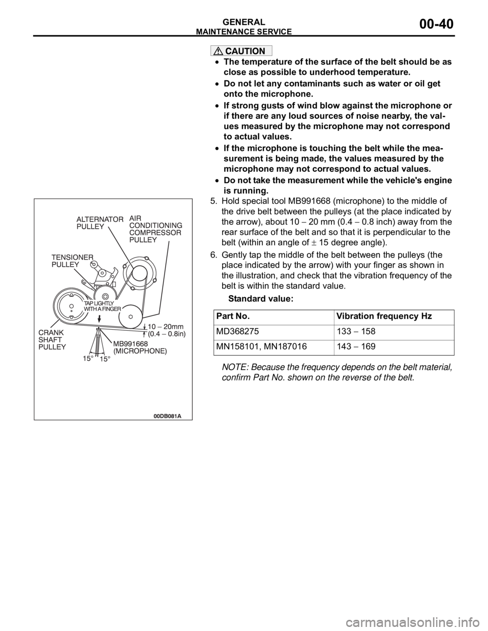
5. Hold special tool MB991668 (microphone) to the middle of
the drive belt between the pulleys (at the place indicated by
the arrow), about 10
20 mm (0.4 0.8 inch) away from the
rear surface of the belt and so that it is perpendicular to the
belt (within an angle of
15 degree angle).
6. Gently tap the middle of the belt between the pulleys (the
place indicated by the arrow) with your finger as shown in
the illustration, and check that the vibration frequency of the
belt is within the standard value.
Standard value:
NOTE: Because the frequency depends on the belt material,
confirm Part No. shown on the reverse of the belt.
.
Part No. Vibration frequency Hz
MD368275 133
158
MN158101, MN187016 143
169
Page 1265 of 1500
MAINTENANCE SERVICE
GENERAL00-44
8. EXHAUST SYSTEM (CONNECTIONS PORTION
OF MUFFLER, MUFFLER PIPES AND
CONVERTER HEAT SHIELDS) (CHECK AND
SERVICE AS REQUIRED)
M1001005800299
1. Check for holes and exhaust gas leaks due to damage,
corrosion, etc.
2. Check the joints and connections for looseness and exhaust
gas leaks.
3. Check the rubber hangers and brackets for damage.
9. ENGINE OIL (CHANGE)M1001002600360
Use the specified oil. (Refer to P.00-35.)
Use care as oil could be hot.
1. After warming up the engine, remove the oil filler cap.
2. Remove the drain plug to allow the engine oil to drain.
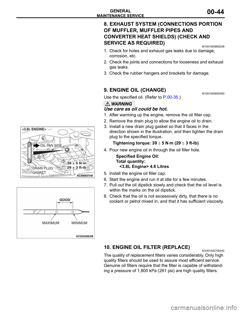
3. Install a new drain plug gasket so that it faces in the
direction shown in the illustration, and then tighten the drain
plug to the specified torque.
Tightening torque: 39
5 Nm (29 3 ft-lb)
4. Pour new engine oil in through the oil filler hole.
Specified Engine Oil:
To ta l q u a n t i t y :
<3.8L Engine> 4.6 Litres
5. Install the engine oil filler cap.
6. Start the engine and run it at idle for a few minutes.
7. Pull out the oil dipstick slowly and check that the oil level is
within the marks on the oil dipstick.
8. Check that the oil is not excessively dirty, that there is no
coolant or petrol mixed in, and that it has sufficient viscosity.
10. ENGINE OIL FILTER (REPLACE)M1001002700345
The quality of replacement filters varies considerably. Only high
quality filters should be used to assure most efficient service.
Genuine oil filters require that the filter is capable of withstand-
ing a pressure of 1,800 kPa (261 psi) are high quality filters.
.
Page 1266 of 1500
MAINTENANCE SERVICE
GENERAL00-45
Engine Oil Filter Selection
This vehicle is equipped with a full-flow, throw-away oil filter.
The same type of filter is recommended as a replacement filter
for this vehicle. It is possible, particularly in cold weather, that
this vehicle may develop high oil pressure for a short duration.
Make sure that any replacement filter used on this vehicle is a
high-quality filter. The filter must withstand a pressure of 1,800
kPa (261 psi) [manufacturer's specifications] to avoid filter and
ultimately engine damage. The Genuine Mitsubishi high-quality
filter and is strongly recommended for use on this vehicle.
Any replacement oil filter should be installed in accordance with
the oil filter manufacturer's installation instructions.
.
Oil Filter Replacement
Use care as oil could be hot.
1. Drain the engine oil by removing the oil drain plug.
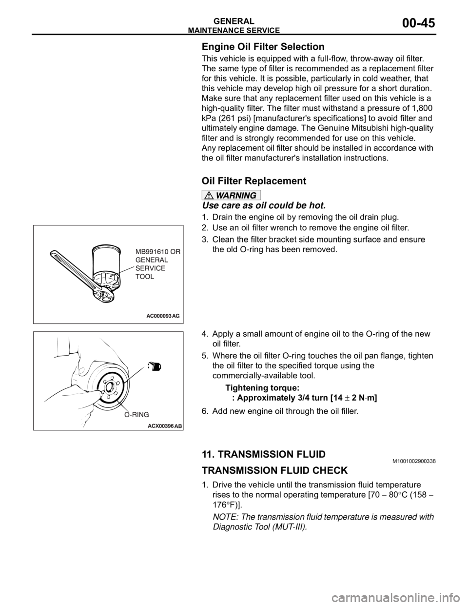
2. Use an oil filter wrench to remove the engine oil filter.
3. Clean the filter bracket side mounting surface and ensure
the old O-ring has been removed.
4. Apply a small amount of engine oil to the O-ring of the new
oil filter.
5. Where the oil filter O-ring touches the oil pan flange, tighten
the oil filter to the specified torque using the
commercially-available tool.
Tightening torque:
: Approximately 3/4 turn [14
2 Nm]
6. Add new engine oil through the oil filler.
11. TRANSMISSION FLUIDM1001002900338
TRANSMISSION FLUID CHECK
1. Drive the vehicle until the transmission fluid temperature
rises to the normal operating temperature [70
80C (158
176
F)].
NOTE: The transmission fluid temperature is measured with
Diagnostic Tool (MUT-III).
Page 1267 of 1500
![MITSUBISHI 380 2005 Workshop Manual MAINTENANCE SERVICE
GENERAL00-46
NOTE: If it takes some amount of time until the transmission
fluid reaches its normal operating temperature [70
80C
(158
176F)], check the transmission fluid lev MITSUBISHI 380 2005 Workshop Manual MAINTENANCE SERVICE
GENERAL00-46
NOTE: If it takes some amount of time until the transmission
fluid reaches its normal operating temperature [70
80C
(158
176F)], check the transmission fluid lev](/manual-img/19/57086/w960_57086-1266.png)
MAINTENANCE SERVICE
GENERAL00-46
NOTE: If it takes some amount of time until the transmission
fluid reaches its normal operating temperature [70
80C
(158
176F)], check the transmission fluid level by refer-
ring to the left diagram.
2. Park the vehicle on a level surface.
3. Move the selector lever through all positions to fill the torque
converter and the hydraulic circuits with fluid, and then move
the selector lever to the "N" position.
4. After wiping off any dirt around the dipstick, remove the
dipstick and check the condition of the transmission fluid.
NOTE: If the transmission fluid smells as if it is burnt, it
means that the transmission fluid has been contaminated by
fine particles from the bushings and friction materials. Tran-
saxle overhaul and cooler line flushing may be necessary.
5. Check transmission fluid level is at the "HOT" mark on the
dipstick. If the transmission fluid level is less than this, add
DIAMOND ATF SP III until the level reaches the "HOT"
mark.
NOTE: If the transmission fluid level is too low, the oil pump
will draw in air along with the transmission fluid, which will
cause to form bubbles. If the transmission fluid level is too
high, rotating components inside the transaxle will churn the
fluid and air into a foamy liquid. Both conditions (level too
low or too high) will cause the hydraulic pressure to drop,
which will result in late shifting and slipping of the clutches
and brakes.
NOTE: In either case, air bubbles can interfere with normal
valve, clutch, and brake operation. Also, foaming can cause
transmission fluid to escape from the transaxle vent where it
may be mistaken for a leak.
Page 1268 of 1500
MAINTENANCE SERVICE
GENERAL00-47
6. Securely insert the dipstick.
NOTE: The transmission fluid should always be replaced
under the following conditions:
.
When troubleshooting the transaxle.
When overhauling the transaxle.
When the transmission fluid is noticeably dirty or burnt
(driving under severe conditions).
TRANSMISSION FLUID CHANGE
Refer to GROUP 23A, Automatic Transmission - On-vehicle
Service P.23A-296.
12. ENGINE COOLANT (CHANGE)M1001003100357
Check the cooling system parts such as the radiator, heater
and oil cooler hoses, thermostat and their connections for leak-
age and damage.
.
CHANGING COOLANT
1. Set the temperature control knob to the "HOT" position.
2. Run the engine until the engine coolant warms, and then
stop the engine.
When removing the radiator cap, use care to avoid
contact with hot coolant or steam. Place a shop towel
over the cap and turn the cap counterclockwise a lit-
tle to let the pressure escape through the vinyl tube.
After relieving the steam pressure, remove the cap by
slowly turning it counterclockwise.
3. Drain the water from the radiator, heater core and engine
after unplugging the radiator drain plug and removing the
radiator cap.
Page 1407 of 1500

EMISSION CONTROL
ENGINE AND EMISSION CONTROL17-76
EMISSION CONTROL
GENERAL DESCRIPTIONM1173000100314
The emission control system consists of the fol-
lowing subsystems:
Positive crankcase ventilation system
Evaporative emission system
Exhaust emission control system
DIAGNOSISM1173000700112
SPECIAL TOOLSM1173000600193
SYMPTOM PROBABLE CAUSE REMEDY
Engine will not start or hard
to startVacuum hose disconnected or damaged Repair or replace
Malfunction of the evaporative emission
purge solenoidRepair or replace
Rough idle or engine stalls
Vacuum hose disconnected or damaged. Repair or replace
Malfunction of the positive crankcase
ventilation valveReplace
Malfunction of the purge control system Check the system; If there is a
problem, check its component
parts.
Excessive oil consumption Positive crankcase ventilation line
cloggedCheck positive crankcase
ventilation system
TOOL TOOL NUMBER AND
NAMESUPERSESSION APPLICATION
MB995061
Purge flow indicatorMLR6890A
Part of MIT280220Inspection of purge
control system
MD998770
Oxygen sensor wrenchMD998770-01 or General
service toolRemoval/installation of
heated oxygen sensor
Page 1461 of 1500
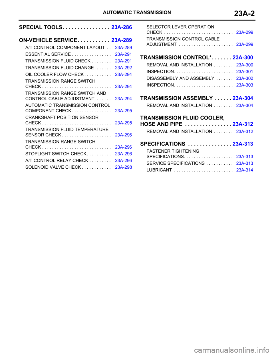
AUTOMATIC TRANSMISSION23A-2
SPECIAL TOOLS . . . . . . . . . . . . . . . .23A-286
ON-VEHICLE SERVICE. . . . . . . . . . .23A-289
A/T CONTROL COMPONENT LAYOUT . . 23A-289
ESSENTIAL SERVICE . . . . . . . . . . . . . . . . 23A-291
TRANSMISSION FLUID CHECK . . . . . . . . 23A-291
TRANSMISSION FLUID CHANGE . . . . . . . 23A-292
OIL COOLER FLOW CHECK . . . . . . . . . . . 23A-294
TRANSMISSION RANGE SWITCH
CHECK . . . . . . . . . . . . . . . . . . . . . . . . . . . . 23A-294
TRANSMISSION RANGE SWITCH AND
CONTROL CABLE ADJUSTMENT. . . . . . . 23A-294
AUTOMATIC TRANSMISSION CONTROL
COMPONENT CHECK . . . . . . . . . . . . . . . . 23A-295
CRANKSHAFT POSITION SENSOR
CHECK . . . . . . . . . . . . . . . . . . . . . . . . . . . . 23A-295
TRANSMISSION FLUID TEMPERATURE
SENSOR CHECK . . . . . . . . . . . . . . . . . . . . 23A-296
TRANSMISSION RANGE SWITCH
CHECK . . . . . . . . . . . . . . . . . . . . . . . . . . . . 23A-296
STOPLIGHT SWITCH CHECK . . . . . . . . . . 23A-296
A/T CONTROL RELAY CHECK . . . . . . . . . 23A-296
SOLENOID VALVE CHECK . . . . . . . . . . . . 23A-298SELECTOR LEVER OPERATION
CHECK . . . . . . . . . . . . . . . . . . . . . . . . . . . . 23A-299
TRANSMISSION CONTROL CABLE
ADJUSTMENT . . . . . . . . . . . . . . . . . . . . . . 23A-299
TRANSMISSION CONTROL* . . . . . . .23A-300
REMOVAL AND INSTALLATION . . . . . . . . 23A-300
INSPECTION. . . . . . . . . . . . . . . . . . . . . . . . 23A-301
DISASSEMBLY AND ASSEMBLY . . . . . . . 23A-302
INSPECTION. . . . . . . . . . . . . . . . . . . . . . . . 23A-303
TRANSMISSION ASSEMBLY . . . . . .23A-304
REMOVAL AND INSTALLATION . . . . . . . . 23A-304
TRANSMISSION FLUID COOLER,
HOSE AND PIPE . . . . . . . . . . . . . . . .23A-312
REMOVAL AND INSTALLATION . . . . . . . . 23A-312
SPECIFICATIONS . . . . . . . . . . . . . . .23A-313
FASTENER TIGHTENING
SPECIFICATIONS. . . . . . . . . . . . . . . . . . . . 23A-313
SERVICE SPECIFICATIONS . . . . . . . . . . . 23A-313
LUBRICANT . . . . . . . . . . . . . . . . . . . . . . . . 23A-314
Page 1486 of 1500
![MITSUBISHI 380 2005 Workshop Manual AUTOMATIC TRANSMISSION DIAGNOSIS
AUTOMATIC TRANSMISSION23A-27
3. Connect the special tools (3.0 MPa (427 psi) oil pressure
gauge [MD998330] and adapters [MD998332, MD998900])
to each pressure discha MITSUBISHI 380 2005 Workshop Manual AUTOMATIC TRANSMISSION DIAGNOSIS
AUTOMATIC TRANSMISSION23A-27
3. Connect the special tools (3.0 MPa (427 psi) oil pressure
gauge [MD998330] and adapters [MD998332, MD998900])
to each pressure discha](/manual-img/19/57086/w960_57086-1485.png)
AUTOMATIC TRANSMISSION DIAGNOSIS
AUTOMATIC TRANSMISSION23A-27
3. Connect the special tools (3.0 MPa (427 psi) oil pressure
gauge [MD998330] and adapters [MD998332, MD998900])
to each pressure discharge port.
NOTE: .
2ND: Second brake pressure port
UD: Underdrive clutch pressure port
LR: Low-reverse brake pressure port
DR: Torque converter release pressure port
DA: Torque converter apply pressure port
RV: Reverse clutch pressure port
OD: Overdrive clutch pressure port
DIR: Direct clutch pressure port
RED: Reduction clutch pressure port
4. Restart the engine.
5. Check that there are no leaks around the special tool port
adapters.
6. Measure the hydraulic pressure at each port under the
conditions given in the standard hydraulic pressure table,
and check that the measured values are within the standard
value ranges.
7. If the pressure is not within the standard value, stop the
engine and refer to the hydraulic pressure test diagnosis
table.
8. Remove the O-ring from the port plug and replace it.
9. Remove the special tool, and install the plugs to the
hydraulic pressure ports.
10.Start the engine and check that there are no leaks around
the plugs.