2005 MITSUBISHI 380 relay
[x] Cancel search: relayPage 1069 of 1500
BODY42-2
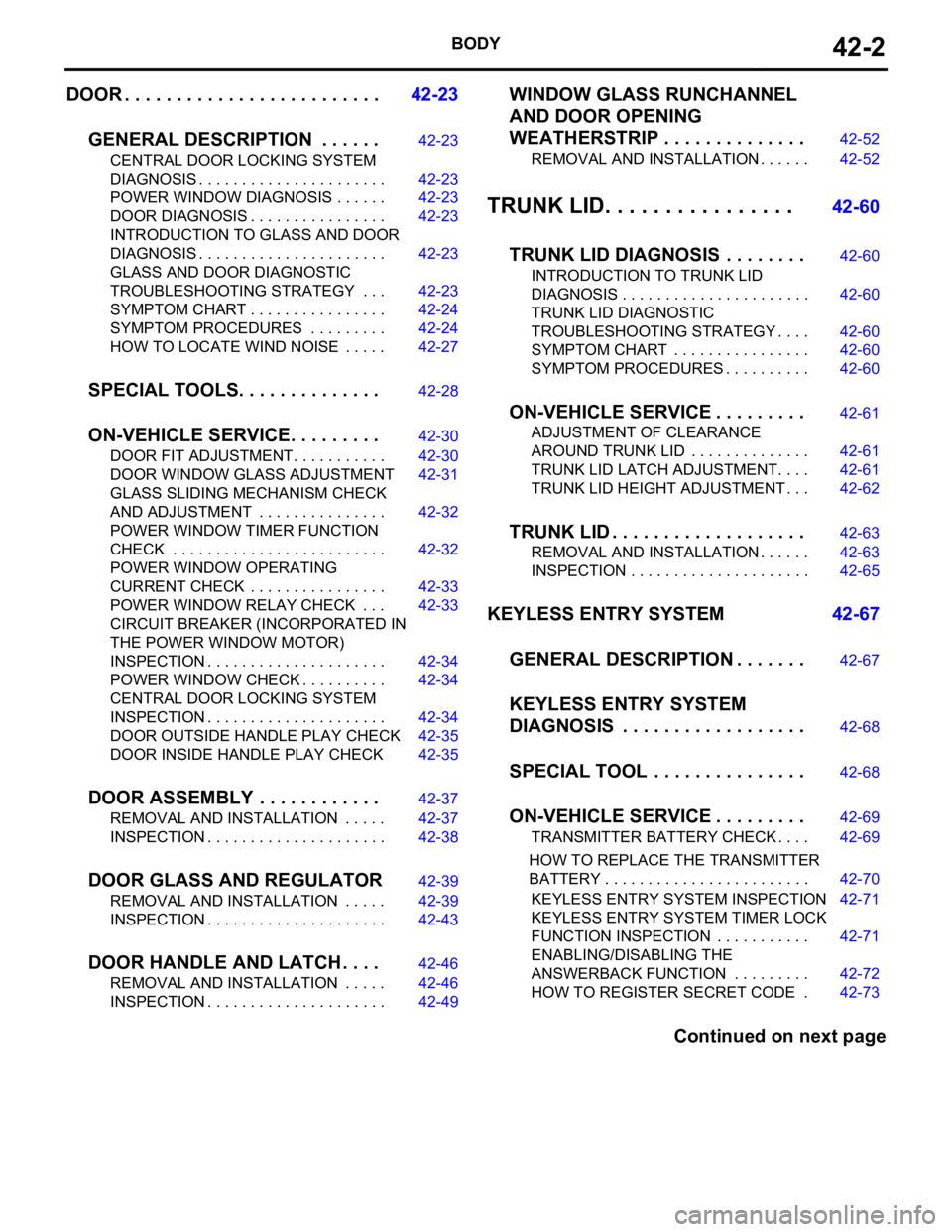
DOOR . . . . . . . . . . . . . . . . . . . . . . . . .42-23
GENERAL DESCRIPTION . . . . . .
42-23
CENTRAL DOOR LOCKING SYSTEM
DIAGNOSIS . . . . . . . . . . . . . . . . . . . . . . 42-23
POWER WINDOW DIAGNOSIS . . . . . . 42-23
DOOR DIAGNOSIS . . . . . . . . . . . . . . . . 42-23
INTRODUCTION TO GLASS AND DOOR
DIAGNOSIS . . . . . . . . . . . . . . . . . . . . . . 42-23
GLASS AND DOOR DIAGNOSTIC
TROUBLESHOOTING STRATEGY . . . 42-23
SYMPTOM CHART . . . . . . . . . . . . . . . . 42-24
SYMPTOM PROCEDURES . . . . . . . . . 42-24
HOW TO LOCATE WIND NOISE . . . . . 42-27
SPECIAL TOOLS. . . . . . . . . . . . . .42-28
ON-VEHICLE SERVICE. . . . . . . . .42-30
DOOR FIT ADJUSTMENT. . . . . . . . . . . 42-30
DOOR WINDOW GLASS ADJUSTMENT42-31
GLASS SLIDING MECHANISM CHECK
AND ADJUSTMENT . . . . . . . . . . . . . . . 42-32
POWER WINDOW TIMER FUNCTION
CHECK . . . . . . . . . . . . . . . . . . . . . . . . . 42-32
POWER WINDOW OPERATING
CURRENT CHECK . . . . . . . . . . . . . . . . 42-33
POWER WINDOW RELAY CHECK . . . 42-33
CIRCUIT BREAKER (INCORPORATED IN
THE POWER WINDOW MOTOR)
INSPECTION . . . . . . . . . . . . . . . . . . . . . 42-34
POWER WINDOW CHECK . . . . . . . . . . 42-34
CENTRAL DOOR LOCKING SYSTEM
INSPECTION . . . . . . . . . . . . . . . . . . . . . 42-34
DOOR OUTSIDE HANDLE PLAY CHECK42-35
DOOR INSIDE HANDLE PLAY CHECK 42-35
DOOR ASSEMBLY . . . . . . . . . . . .42-37
REMOVAL AND INSTALLATION . . . . . 42-37
INSPECTION . . . . . . . . . . . . . . . . . . . . . 42-38
DOOR GLASS AND REGULATOR42-39
REMOVAL AND INSTALLATION . . . . . 42-39
INSPECTION . . . . . . . . . . . . . . . . . . . . . 42-43
DOOR HANDLE AND LATCH . . . .42-46
REMOVAL AND INSTALLATION . . . . . 42-46
INSPECTION . . . . . . . . . . . . . . . . . . . . . 42-49
WINDOW GLASS RUNCHANNEL
AND DOOR OPENING
WEATHERSTRIP . . . . . . . . . . . . . .
42-52
REMOVAL AND INSTALLATION . . . . . . 42-52
TRUNK LID. . . . . . . . . . . . . . . . 42-60
TRUNK LID DIAGNOSIS . . . . . . . .
42-60
INTRODUCTION TO TRUNK LID
DIAGNOSIS . . . . . . . . . . . . . . . . . . . . . . 42-60
TRUNK LID DIAGNOSTIC
TROUBLESHOOTING STRATEGY . . . . 42-60
SYMPTOM CHART . . . . . . . . . . . . . . . . 42-60
SYMPTOM PROCEDURES . . . . . . . . . . 42-60
ON-VEHICLE SERVICE . . . . . . . . .42-61
ADJUSTMENT OF CLEARANCE
AROUND TRUNK LID . . . . . . . . . . . . . . 42-61
TRUNK LID LATCH ADJUSTMENT. . . . 42-61
TRUNK LID HEIGHT ADJUSTMENT . . . 42-62
TRUNK LID . . . . . . . . . . . . . . . . . . .42-63
REMOVAL AND INSTALLATION . . . . . . 42-63
INSPECTION . . . . . . . . . . . . . . . . . . . . . 42-65
KEYLESS ENTRY SYSTEM 42-67
GENERAL DESCRIPTION . . . . . . .
42-67
KEYLESS ENTRY SYSTEM
DIAGNOSIS . . . . . . . . . . . . . . . . . .
42-68
SPECIAL TOOL . . . . . . . . . . . . . . .42-68
ON-VEHICLE SERVICE . . . . . . . . .42-69
TRANSMITTER BATTERY CHECK . . . . 42-69
HOW TO REPLACE THE TRANSMITTER
BATTERY . . . . . . . . . . . . . . . . . . . . . . . . 42-70
KEYLESS ENTRY SYSTEM INSPECTION42-71
KEYLESS ENTRY SYSTEM TIMER LOCK
FUNCTION INSPECTION . . . . . . . . . . . 42-71
ENABLING/DISABLING THE
ANSWERBACK FUNCTION . . . . . . . . . 42-72
HOW TO REGISTER SECRET CODE . 42-73
Continued on next page
Page 1100 of 1500
DOOR
BODY42-33
POWER WINDOW OPERATING CURRENT CHECKM1429001100195
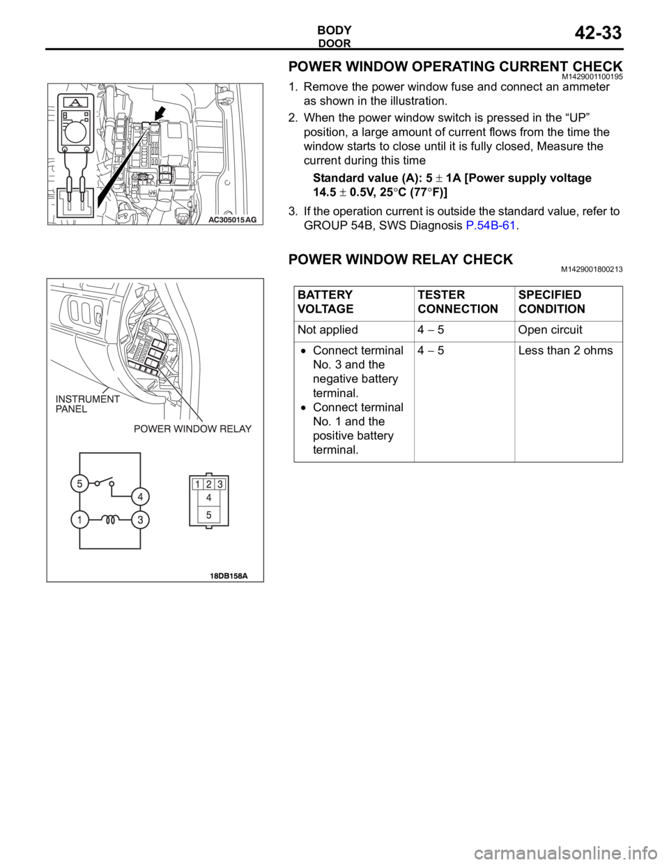
1. Remove the power window fuse and connect an ammeter
as shown in the illustration.
2. When the power window switch is pressed in the “UP”
position, a large amount of current flows from the time the
window starts to close until it is fully closed, Measure the
current during this time
Standard value (A): 5
1A [Power supply voltage
14.5
0.5V, 25C (77F)]
3. If the operation current is outside the standard value, refer to
GROUP 54B, SWS Diagnosis P.54B-61.
POWER WINDOW RELAY CHECKM1429001800213
BATTERY
VOLTAGETESTER
CONNECTIONSPECIFIED
CONDITION
Not applied 4
5 Open circuit
Connect terminal
No. 3 and the
negative battery
terminal.
Connect terminal
No. 1 and the
positive battery
terminal.4
5 Less than 2 ohms
Page 1288 of 1500
TRACTION CONTROL SYSTEM (TCL) DIAGNOSIS
TRACTION CONTROL SYSTEM (TCL)13C-9
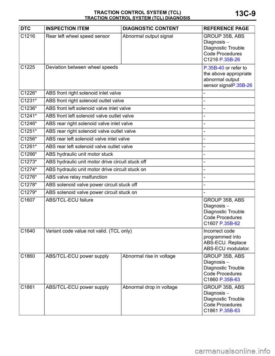
C1216 Rear left wheel speed sensor Abnormal output signal GROUP 35B, ABS
Diagnosis
Diagnostic Trouble
Code Procedures
C1216 P.35B-26
C1225 Deviation between wheel speeds
P.35B-40 or refer to
the above appropriate
abnormal output
sensor signalP.35B-26
C1226* ABS front right solenoid inlet valve -
C1231* ABS front right solenoid outlet valve -
C1236* ABS front left solenoid valve inlet valve -
C1241* ABS front left solenoid valve outlet valve -
C1246* ABS rear right solenoid valve inlet valve -
C1251* ABS rear right solenoid valve outlet valve -
C1256* ABS rear left solenoid valve inlet valve -
C1261* ABS rear left solenoid valve outlet valve -
C1266* ABS hydraulic unit motor stuck -
C1273* ABS hydraulic unit motor drive circuit stuck off -
C1274* ABS hydraulic unit motor drive circuit stuck on -
C1276* ABS valve relay malfunction -
C1278* ABS solenoid valve power circuit stuck off -
C1279* ABS solenoid valve power circuit stuck on -
C1607 ABS/TCL-ECU failure GROUP 35B, ABS
Diagnosis
Diagnostic Trouble
Code Procedures
C1607 P.35B-62
C1640 Variant code value not valid. (TCL only) Incorrect code
programmed into
ABS-ECU. Replace
ABS-ECU modulator.
C1860 ABS/TCL-ECU power supply Abnormal rise in voltage GROUP 35B, ABS
Diagnosis
Diagnostic Trouble
Code Procedures
C1860 P.35B-63
C1861 ABS/TCL-ECU power supply Abnormal drop in voltage GROUP 35B, ABS
Diagnosis
Diagnostic Trouble
Code Procedures
C1861 P.35B-63 DTC INSPECTION ITEM DIAGNOSTIC CONTENT REFERENCE PAGE
Page 1315 of 1500

TRACTION CONTROL SYSTEM (TCL) DIAGNOSIS
TRACTION CONTROL SYSTEM (TCL)13C-36
DATA LIST REFERENCE TABLEM1136003500071
NOTE: If the ABS-8 ECU or the active wheel
speed sensor are disconnected, or if the wiring is
an open/ short circuit, the ABS 8 ECU will shut
off power supply to the respective wheel speed
sensor. All other wheel speed sensors will oper-
ate normally. To restore the power supply, the
ignition switch must be turned to the "OFF" posi-
tion then to the "ON" position again.The following items can be read by the diagnostic
tool from the ABS/TCL-ECU input data. (Refer to
P.13C-3).
NOTE: Since the TCL is controlled with the same ABS/TCL-ECU used to control the ABS, the stoplight switch
check item (No.6) used only for the ABS also appear.MUT-III
DIAGNOSTI
C TOOL
DISPLAYITEM
NO.CHECK ITEM CHECKING REQUIREMENTS NORMAL
VA L U E
FL wheel
speed sensor01 Front left wheel speed sensor Drive the vehicle Vehicle speeds
displayed on the
speedometer
and diagnostic
tool are identical. FR wheel
speed sensor02 Front right wheel speed sensor
RL wheel
speed sensor03 Rear left wheel speed sensor
RR wheel
speed sensor04 Rear right left wheel speed
sensor
Power supply
voltage05 ABS/TCL-ECU power supply
voltageIgnition switch power supply
voltageBattery positive
voltage
Stoplamp
switch
(input)*06 Stoplamp switch Depress the brake pedal. ON
Release the brake pedal. OFF
Stoplamp
switch*13 Stoplamp switch Depress the brake pedal. ON
Release the brake pedal. OFF
Pump motor 21 Pump motor When the ABS outputs the
operation permission signal
during drivingON
When the ABS outputs the
operation permission signal
during drivingOFF
Valve relay 30 Valve relayWhen the ABS outputs the
operation permission signal
during drivingON
When the ABS outputs the
operation permission signal
during drivingOFF
TCL mode 35 TCL operation When the TCL outputs the
operation permission signal
during drivingON
When the TCL outputs the
operation inhibition signal
during drivingOFF
Page 1322 of 1500
TRACTION CONTROL SYSTEM (TCL) DIAGNOSIS
TRACTION CONTROL SYSTEM (TCL)13C-43
(7) The recommended Supply Voltage at terminals 16, 9, 6,
and 8 are:
Set value: 10.0Volts - 14.5Volts
Q: Is the supply voltage within the set value?
YES : Check wheel speed sensor signal at ABS-ECU using
an oscillopscope
NO :
Refer to Power supply systemP.35B-63
Refer to Motor supply systemP.35B-48
Refer to Valve relay systemP.35B-56
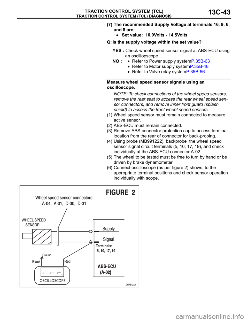
Measure wheel speed sensor signals using an
oscilloscope.
NOTE: To check connections of the wheel speed sensors,
remove the rear seat to access the rear wheel speed sen-
sor connectors, and remove inner front guard (splash
shield) to access the front wheel speed sensors.
(1) Wheel speed sensor must remain connected to measure
active sensor.
(2) ABS-ECU must remain connected.
(3) Remove ABS connector protection cap to access terminal
location from the rear of connector for back-probing.
(4) Using probe (MB991222), backprobe the wheel speed
sensor signal circuit terminals (5, 10, 17, 19), and check
individually at the ABS-ECU connector A-02
(5) The wheel to be tested must be free to turn by hand or be
driven by brake dynamometer
(6) Connect oscilloscope (as per figure 2) shows, to the
appropriate terminal positions and check sensor operation
individually with scope.
Page 1372 of 1500
AUTO-CRUISE CONTROL
ENGINE AND EMISSION CONTROL17-41
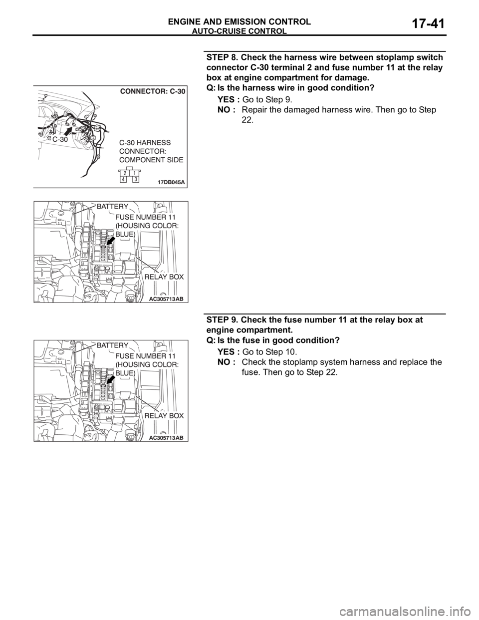
STEP 8. Check the harness wire between stoplamp switch
connector C-30 terminal 2 and fuse number 11 at the relay
box at engine compartment for damage.
Q: Is the harness wire in good condition?
YES : Go to Step 9.
NO : Repair the damaged harness wire. Then go to Step
22.
STEP 9. Check the fuse number 11 at the relay box at
engine compartment.
Q: Is the fuse in good condition?
YES : Go to Step 10.
NO : Check the stoplamp system harness and replace the
fuse. Then go to Step 22.
Page 1461 of 1500
AUTOMATIC TRANSMISSION23A-2
SPECIAL TOOLS . . . . . . . . . . . . . . . .23A-286
ON-VEHICLE SERVICE. . . . . . . . . . .23A-289
A/T CONTROL COMPONENT LAYOUT . . 23A-289
ESSENTIAL SERVICE . . . . . . . . . . . . . . . . 23A-291
TRANSMISSION FLUID CHECK . . . . . . . . 23A-291
TRANSMISSION FLUID CHANGE . . . . . . . 23A-292
OIL COOLER FLOW CHECK . . . . . . . . . . . 23A-294
TRANSMISSION RANGE SWITCH
CHECK . . . . . . . . . . . . . . . . . . . . . . . . . . . . 23A-294
TRANSMISSION RANGE SWITCH AND
CONTROL CABLE ADJUSTMENT. . . . . . . 23A-294
AUTOMATIC TRANSMISSION CONTROL
COMPONENT CHECK . . . . . . . . . . . . . . . . 23A-295
CRANKSHAFT POSITION SENSOR
CHECK . . . . . . . . . . . . . . . . . . . . . . . . . . . . 23A-295
TRANSMISSION FLUID TEMPERATURE
SENSOR CHECK . . . . . . . . . . . . . . . . . . . . 23A-296
TRANSMISSION RANGE SWITCH
CHECK . . . . . . . . . . . . . . . . . . . . . . . . . . . . 23A-296
STOPLIGHT SWITCH CHECK . . . . . . . . . . 23A-296
A/T CONTROL RELAY CHECK . . . . . . . . . 23A-296
SOLENOID VALVE CHECK . . . . . . . . . . . . 23A-298SELECTOR LEVER OPERATION
CHECK . . . . . . . . . . . . . . . . . . . . . . . . . . . . 23A-299
TRANSMISSION CONTROL CABLE
ADJUSTMENT . . . . . . . . . . . . . . . . . . . . . . 23A-299
TRANSMISSION CONTROL* . . . . . . .23A-300
REMOVAL AND INSTALLATION . . . . . . . . 23A-300
INSPECTION. . . . . . . . . . . . . . . . . . . . . . . . 23A-301
DISASSEMBLY AND ASSEMBLY . . . . . . . 23A-302
INSPECTION. . . . . . . . . . . . . . . . . . . . . . . . 23A-303
TRANSMISSION ASSEMBLY . . . . . .23A-304
REMOVAL AND INSTALLATION . . . . . . . . 23A-304
TRANSMISSION FLUID COOLER,
HOSE AND PIPE . . . . . . . . . . . . . . . .23A-312
REMOVAL AND INSTALLATION . . . . . . . . 23A-312
SPECIFICATIONS . . . . . . . . . . . . . . .23A-313
FASTENER TIGHTENING
SPECIFICATIONS. . . . . . . . . . . . . . . . . . . . 23A-313
SERVICE SPECIFICATIONS . . . . . . . . . . . 23A-313
LUBRICANT . . . . . . . . . . . . . . . . . . . . . . . . 23A-314
Page 1472 of 1500
AUTOMATIC TRANSMISSION DIAGNOSIS
AUTOMATIC TRANSMISSION23A-13
A/T DIAGNOSTIC TROUBLESHOOTING STRATEGYM1231007600339
Use these steps to plan your diagnostic strategy. If
you follow them carefully, you will find most A/T mal-
functions.
1. Gather as much information as possible about the
complaint from the customer.
2. Verify that the condition described by the
customer exists.
3. Check the vehicle for any A/T Diagnostic Trouble
Codes (DTCs).
4. If you can not verify the condition and there are no
DTCs, the malfunction is intermittent. For
information on how to cope with intermittent
malfunctions, refer to GROUP 00, How to Use
Troubleshooting/Inspection Service Points
How
to Cope with Intermittent Malfunction P.00-14.
5. If you can verify the condition but there are no
DTCs, or the system can not communicate with
diagnostic tool, refer to the Symptom Chart
P.23A-35.6. If there is a DTC, record the number of the code,
then erase the code from memory using
diagnostic tool.
7. Reconfirm the symptom with a Road Test.
8. If a DTC is set again, go to the Inspection Chart
for Diagnostic Trouble Codes.
9. If a DTC is not set again, the malfunction is
intermittent. For information on how to cope with
intermittent malfunctions, refer to GROUP 00,
How to Use Troubleshooting/Inspection Service
Points
How to Cope with Intermittent
Malfunction P.00-14.
10.After repairs are completed, conduct a Road Test
duplicating the complaint conditions to confirm the
malfunction has been eliminated.
DIAGNOSTIC FUNCTIONM1231022500135
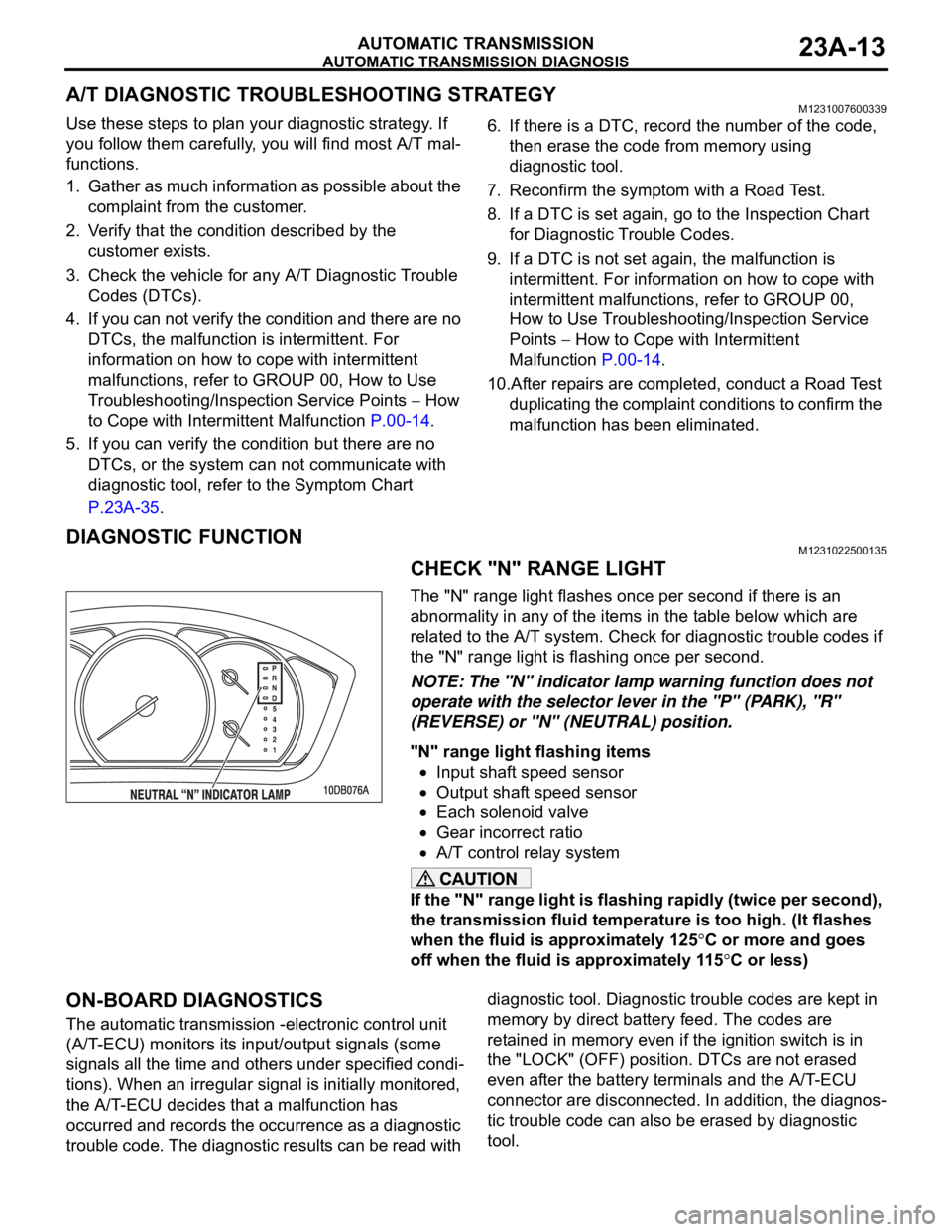
CHECK "N" RANGE LIGHT
The "N" range light flashes once per second if there is an
abnormality in any of the items in the table below which are
related to the A/T system. Check for diagnostic trouble codes if
the "N" range light is flashing once per second.
NOTE: The "N" indicator lamp warning function does not
operate with the selector lever in the "P" (PARK), "R"
(REVERSE) or "N" (NEUTRAL) position.
"N" range light flashing items
Input shaft speed sensor
Output shaft speed sensor
Each solenoid valve
Gear incorrect ratio
A/T control relay system
If the "N" range light is flashing rapidly (twice per second),
the transmission fluid temperature is too high. (It flashes
when the fluid is approximately 125
C or more and goes
off when the fluid is approximately 115
C or less)
ON-BOARD DIAGNOSTICS
The automatic transmission -electronic control unit
(A/T-ECU) monitors its input/output signals (some
signals all the time and others under specified condi-
tions). When an irregular signal is initially monitored,
the A/T-ECU decides that a malfunction has
occurred and records the occurrence as a diagnostic
trouble code. The diagnostic results can be read with diagnostic tool. Diagnostic trouble codes are kept in
memory by direct battery feed. The codes are
retained in memory even if the ignition switch is in
the "LOCK" (OFF) position. DTCs are not erased
even after the battery terminals and the A/T-ECU
connector are disconnected. In addition, the diagnos-
tic trouble code can also be erased by diagnostic
tool.