Page 928 of 1500
ENGINE COOLING DIAGNOSIS
ENGINE COOLING14-13
STEP 13. Check the continuity between fan control relay
connector A-10X and body earth.
(1) Disconnect fan control relay connector A-10X (remove the
fan control relay) and measure relay box side connector.
(2) Measure the resistance between fan control relay connector
A-10X terminal 1 and body earth.
Continuity exists.
(3) Connect fan control relay connector A-10X (install the fan
control relay).
Q: Does the continuity exists?
YES : An intermittent malfunction is suspected (Refer to
00-7).
NO : Go to Step 14.
STEP 14. Check the fan control relay connector A-10X.
Q: Is the connector in good condition?
YES : Go to Step 15.
NO : Repair the connector or replace the relay box. Then
go to Step 24.
Page 929 of 1500
ENGINE COOLING DIAGNOSIS
ENGINE COOLING14-14
STEP 15. Check the earth connector A-14.
Q: Is the connector in good condition?
YES : Go to Step 16.
NO : Repair or replace the connector. Then go to Step 24.
STEP 16. Check the harness wire between fan control relay
connector A-10X terminal 1 and body earth connector A-14
terminal 6.
Q: Is the harness wire in good condition?
YES : An intermittent malfunction is suspected (Refer to
GROUP 00 - How to use troubleshooting 00-7).
NO : Repair the damaged harness wire. Then go to Step
24.
Page 935 of 1500
Page 936 of 1500
ENGINE COOLING DIAGNOSIS
ENGINE COOLING14-21
STEP 2. Check the fan control relay connector A-10X.
Q: Is the connector in good condition?
YES : Go to Step 3.
NO : Repair the connector or replace the relay box. Then
go to Step 8.
STEP 3. Check the harness wire between fan control relay
connector A-10X terminal 2 and fan controller connector
A-24 terminal 3.
Q: Is the harness wire in good condition?
YES : Go to Step 4.
NO : Repair the damaged harness wire. Then go to Step 8.
Page 946 of 1500
ON-VEHICLE SERVICE
ENGINE COOLING14-31
FAN CONTROL RELAY CONTINUITY CHECKM1141006200310
BATTERY
VOLTAGETERMINAL NO. TO
BE CONNECTED
TO TESTERCONTINUITY TEST
RESULTS
Not applied 4
2 Open circuit
Connect
terminal No.3
and battery (
)
terminal.
Connect
terminal No.1
and battery (+)
terminal.4
2 Less than 2 ohms
Page 966 of 1500
Page 1008 of 1500

IGNITION SYSTEM
ENGINE ELECTRICAL16-31
ON-VEHICLE SERVICE
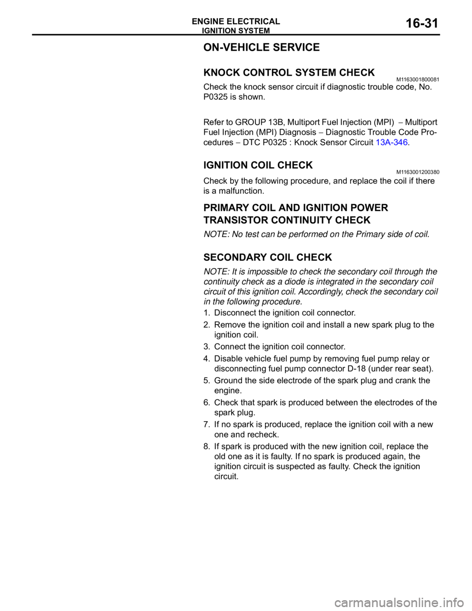
KNOCK CONTROL SYSTEM CHECKM1163001800081
Check the knock sensor circuit if diagnostic trouble code, No.
P0325 is shown.
Refer to GROUP 13B, Multiport Fuel Injection (MPI)
Multiport
Fuel Injection (MPI) Diagnosis
Diagnostic Trouble Code Pro-
cedures
DTC P0325 : Knock Sensor Circuit 13A-346.
IGNITION COIL CHECK M1163001200380
Check by the following procedure, and replace the coil if there
is a malfunction.
.
PRIMARY COIL AND IGNITION POWER
TRANSISTOR CONTINUITY CHECK
NOTE: No test can be performed on the Primary side of coil.
.
SECONDARY COIL CHECK
NOTE: It is impossible to check the secondary coil through the
continuity check as a diode is integrated in the secondary coil
circuit of this ignition coil. Accordingly, check the secondary coil
in the following procedure.
1. Disconnect the ignition coil connector.
2. Remove the ignition coil and install a new spark plug to the
ignition coil.
3. Connect the ignition coil connector.
4. Disable vehicle fuel pump by removing fuel pump relay or
disconnecting fuel pump connector D-18 (under rear seat).
5. Ground the side electrode of the spark plug and crank the
engine.
6. Check that spark is produced between the electrodes of the
spark plug.
7. If no spark is produced, replace the ignition coil with a new
one and recheck.
8. If spark is produced with the new ignition coil, replace the
old one as it is faulty. If no spark is produced again, the
ignition circuit is suspected as faulty. Check the ignition
circuit.
Page 1047 of 1500

WINDSHIELD WIPER AND WASHER
EXTERIOR51-14
WINDSHIELD WIPER AND WASHER
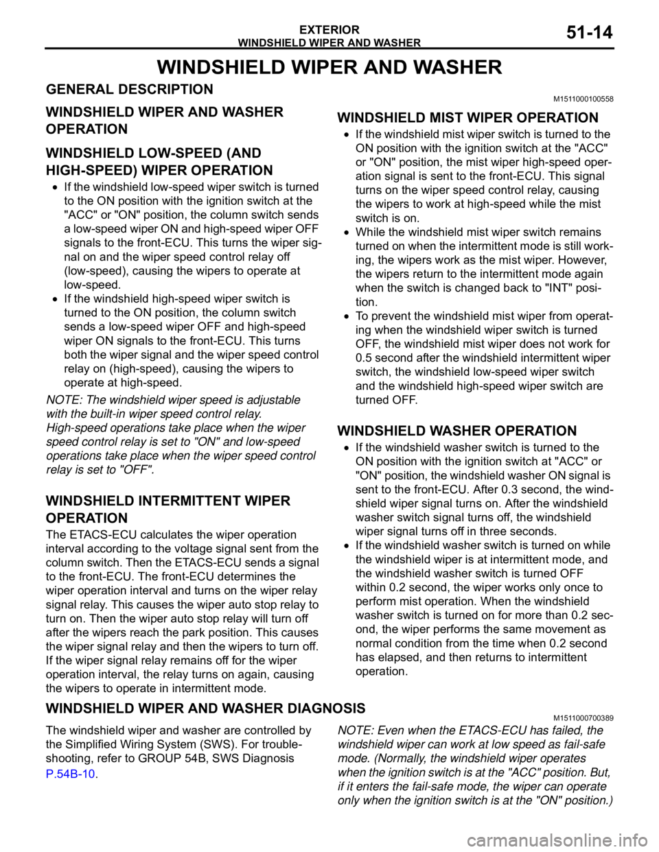
GENERAL DESCRIPTIONM1511000100558
WINDSHIELD WIPER AND WASHER
OPERATION
.
WINDSHIELD LOW-SPEED (AND
HIGH-SPEED) WIPER OPERATION
If the windshield low-speed wiper switch is turned
to the ON position with the ignition switch at the
"ACC" or "ON" position, the column switch sends
a low-speed wiper ON and high-speed wiper OFF
signals to the front-ECU. This turns the wiper sig-
nal on and the wiper speed control relay off
(low-speed), causing the wipers to operate at
low-speed.
If the windshield high-speed wiper switch is
turned to the ON position, the column switch
sends a low-speed wiper OFF and high-speed
wiper ON signals to the front-ECU. This turns
both the wiper signal and the wiper speed control
relay on (high-speed), causing the wipers to
operate at high-speed.
NOTE: The windshield wiper speed is adjustable
with the built-in wiper speed control relay.
High-speed operations take place when the wiper
speed control relay is set to "ON" and low-speed
operations take place when the wiper speed control
relay is set to "OFF".
.
WINDSHIELD INTERMITTENT WIPER
OPERATION
The ETACS-ECU calculates the wiper operation
interval according to the voltage signal sent from the
column switch. Then the ETACS-ECU sends a signal
to the front-ECU. The front-ECU determines the
wiper operation interval and turns on the wiper relay
signal relay. This causes the wiper auto stop relay to
turn on. Then the wiper auto stop relay will turn off
after the wipers reach the park position. This causes
the wiper signal relay and then the wipers to turn off.
If the wiper signal relay remains off for the wiper
operation interval, the relay turns on again, causing
the wipers to operate in intermittent mode.
.
WINDSHIELD MIST WIPER OPERATION
If the windshield mist wiper switch is turned to the
ON position with the ignition switch at the "ACC"
or "ON" position, the mist wiper high-speed oper-
ation signal is sent to the front-ECU. This signal
turns on the wiper speed control relay, causing
the wipers to work at high-speed while the mist
switch is on.
While the windshield mist wiper switch remains
turned on when the intermittent mode is still work-
ing, the wipers work as the mist wiper. However,
the wipers return to the intermittent mode again
when the switch is changed back to "INT" posi-
tion.
To prevent the windshield mist wiper from operat-
ing when the windshield wiper switch is turned
OFF, the windshield mist wiper does not work for
0.5 second after the windshield intermittent wiper
switch, the windshield low-speed wiper switch
and the windshield high-speed wiper switch are
turned OFF.
.
WINDSHIELD WASHER OPERATION
If the windshield washer switch is turned to the
ON position with the ignition switch at "ACC" or
"ON" position, the windshield washer ON signal is
sent to the front-ECU. After 0.3 second, the wind-
shield wiper signal turns on. After the windshield
washer switch signal turns off, the windshield
wiper signal turns off in three seconds.
If the windshield washer switch is turned on while
the windshield wiper is at intermittent mode, and
the windshield washer switch is turned OFF
within 0.2 second, the wiper works only once to
perform mist operation. When the windshield
washer switch is turned on for more than 0.2 sec-
ond, the wiper performs the same movement as
normal condition from the time when 0.2 second
has elapsed, and then returns to intermittent
operation.
WINDSHIELD WIPER AND WASHER DIAGNOSISM1511000700389
The windshield wiper and washer are controlled by
the Simplified Wiring System (SWS). For trouble-
shooting, refer to GROUP 54B, SWS Diagnosis
P.54B-10.NOTE: Even when the ETACS-ECU has failed, the
windshield wiper can work at low speed as fail-safe
mode. (Normally, the windshield wiper operates
when the ignition switch is at the "ACC" position. But,
if it enters the fail-safe mode, the wiper can operate
only when the ignition switch is at the "ON" position.)